1982 Citroen CX engine oil
[x] Cancel search: engine oilPage 116 of 394

Downloaded from www.Manualslib.com manuals search engine Op. MA.IE. 144-O 1 I - PRECAUTIONS TO BE TAKEN WHEN WORKII;(G ON A VEHICLE FITTED WITH THE (t L-JETRONIC n
SYSTEM.
1.
Do not run the engine if the battery leads are improperly secured
2. Do not use a quick-start charging trolley for starting the engine
3. Never disconnect the battery with the engine running
4. When charging the battery, disconnect the leads
5. Before checking the injection system, check the ignition : (advance, advance curve, proper grade of plugs 1
6. Remove the E C U before putting the vehicle through a paint-stoving oven
7. Check the conditions of the various connections
8. Never disconnect the E,C U. while the ignition is on
9. When checking compression, disconnect the positive terminal of the coil (in order to stop the injection signal). 10.
When carrying out a check requiring an ohmmeter, use exclusively a battery-powered ohmmeter. II. FAULT-FINDING.
1. THE ENGINE DOES NOT START, OR IS DIFFICULT TO START . . . . . . . . . . . . . . . . . . . . . . . . . . . . . . . . . . . . . . . . . . . . . . . . . . . . . . . . P. 2
2. THE ENGINE STARTS, THEN STOPS . . . . . . . . . . . . . . . . . . . . . . . . . . . . . . . . . . . . . . . . . . . . . . . . . . . . . . . . . . . . . . . . . . . . . . . . . . . . . . . . . . . . . . . . . . . . . . . . . . . . . . P. 3
3. UNSTABLE OR INCORRECT IDLING SPEED, EXCESSIVE FUEL CONSUMPTION ........................ P:5
-4. ENGINE MISFIRES AT .ALL SPEEDS ........................................................................................................
P. 7
5. LACK OF POWER . . . . . . . . . . . . . . . . . . . . . . . . . . . . . . . . . . . . . . . . . . . . . . . . . . . . . . . . . . . . . . . . . . . . . . . . . . . . . . . . . . . . . . . . . . . . . . . . . . . . . . . . . . . . . . . . . . . . . . . . ................ P. 9
Page 136 of 394

Downloaded from www.Manualslib.com manuals search engine 5. Air-flow sensor ( DIAGRAM 5 )
- Disconnect the E.C.U.
- Using an ohmmeter check the continuity of circuits (( 6 )a, H 7 )) (( 8 H and (( 9 )) linking the air-flow sensor to
the multiple terminal board. as well as the continuity between each of the terminals
- The air-flow meter does not require any maintenance. It is not necessary to oil the flop. It must work without
high spot or catching
When the air-flow sensor is removed blank off the ducts so OS to protect it from dust
- Check the air circuit for air-tightness.
6. Resistors and injectors :
- A dirty injector may cause o lock of power. or on unstable idling speed.
- It is possible to test the functioning of the injectors with the engine idling by disconnecting each injector
in turn the engine rpm should decrease each time.
- Disconnect the E C U
- The resistance of an injector is 2 to 3 II.
- Each supplementary resistance is 5 to 7 R
- The volume delivered by an injector ( kept constantly open and under the normal operating pressure ) is
approximately 200 cm3 /min ( 12 25 cu in/min )-
- If the rubber pipe on one of the injectors appears wet on the outside, the injector must be replaced.
- Using an ohmmeter, check the continuity of the circuits
Page 139 of 394

Downloaded from www.Manualslib.com manuals search engine 7. Water temperature sensor : ( DIAGRAM 7 )
- Disconnecting ‘the water temperature sensor should cause the engine to stall. when hot.
- Disconnect the E.C U
Using the ohmmeter, test the continuity of the circuit. and measure directly the resisitance using the sensor
cc - 10’ C )) R = 7 to 12 kR
cc + 20” C )t R = 2 to 3 kQ
cc t 80” C H R -. 250 to 400 Q
e
2
ii 8. Air temperature sensor : ( DIAGRAM 8 )
E
-E
?
U-J
- Disconnect the E.C.U. -
Using an ohmmeter, test the continuity of the circuit. and measure the resistance of the sensor between
terminals (( 6 )) and (( 27 ))
(c-10’ CH. R-8toIlkQ
N t 20” C 1) R = 2 to 3 kQ
tt + 50” C n R x 750 to 900 !J
Page 149 of 394

Downloaded from www.Manualslib.com manuals search engine 28 OPERATION N” MA.IE. 144-O : Ch <,c ,ng n,,d nlfjusfiup Ihe u I.-~<~tro,,ir i) <~lrr/mr,ir k’
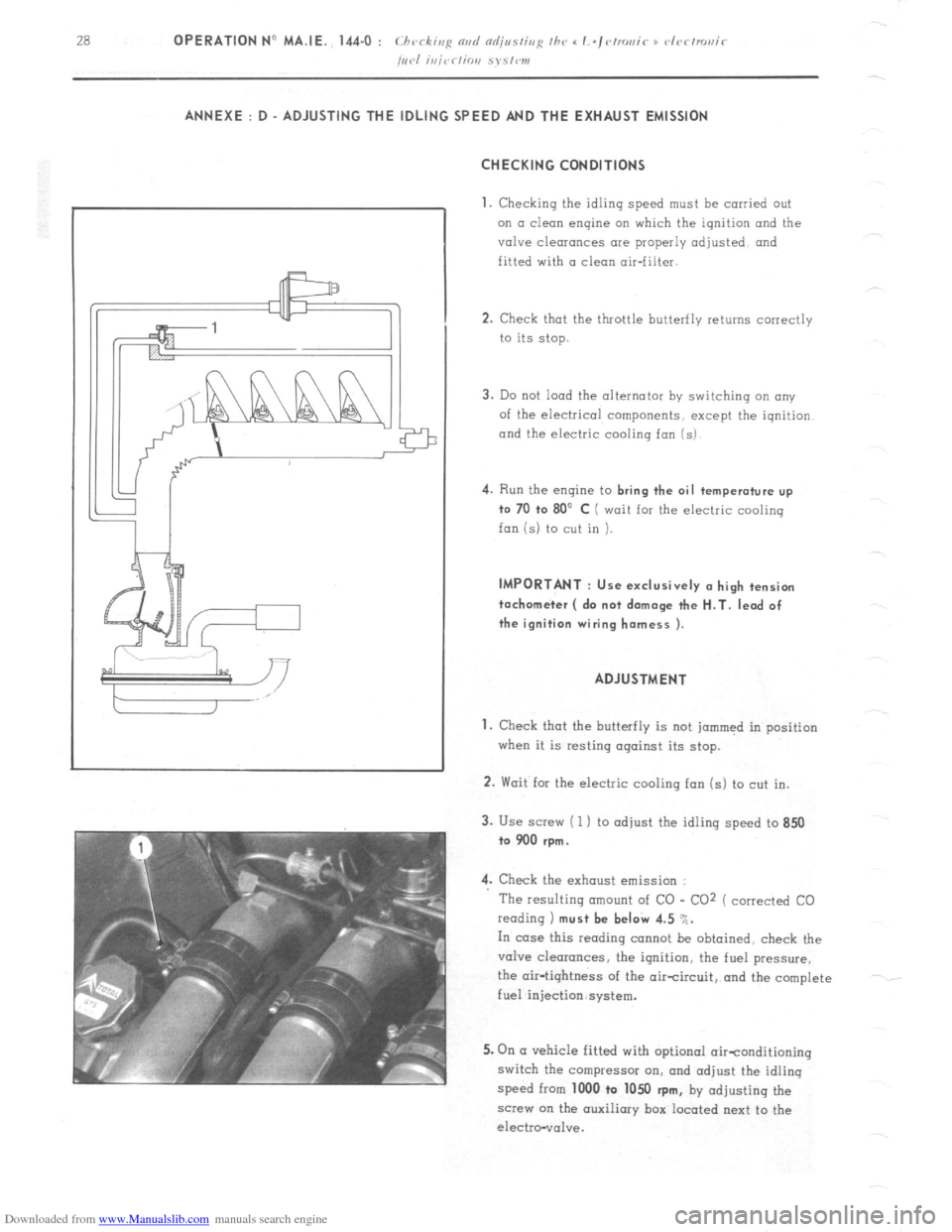
/,,,.I i,,jrr/io,, S~S,W1, ANNEXE : D - ADJUSTING THE IDLING SPEED AND THE EXHAUST EMISSION
CHECKING CONDITIONS
1.
Checking the idling speed must be carried out
on a clean engine on which the ignition and the
valve clearances are properly adjusted and
fitted with a clean air-filter.
2. Check that the throttle butterfly returns correctly
to its stop.
3. Do not load the alternator by switching an any
of the electrical components, except the iqnition
and the electric cooling fan (s) 4.
Run the engine to bring the oil temperature up
to 70 +o 80’ C ( wait for the electric cooling
fan is) to cut in ). IMPORTANT : Use exclusively (I high tension
tachometer ( do not damage the H.T. lead of
the ignition wiring harness ).
ADJUSTMENT
1. Check that the butterfly is not jammed in position
when it is resting against its stop.
2. Wait for the electric cooling fan (s) to cut in.
3. Use screw ( 1 ) to adjust the idling speed to 850
to 900 rpm.
4. Check the exhaust emission :
The resulting amount of CO - CO2 ( corrected CO
reading 1 must be beI& 4.5 %.
In case this reading cannot be obtained, check the
valve clearances, the ignition, the fuel pressure,
the air-tightness of the aircircuit, and the complete
fuel injection system.
5. On (I vehicle fitted with optional oirtonditioning
switch the compressor on, and adjust the idling
speed from 1000 to 1050
rpm, by adjusting the
screw on the auxiliary box located next to the
electro-vol”e.
Page 153 of 394

Downloaded from www.Manualslib.com manuals search engine 2 OPERATION No MA. 210-00 :~~‘hornc:cris:ics mri special /~~nttrrc,.s o,/ /he ig/litiorl Spark plug gap .,...._.......,...,. ,..._. ,...... ., ,, ,,
Q.6 to 0.7 mm
1 iqhtenrng torque ( cylinder head cold ) .._..._._........._.......... .20 to 25 mN ( 2 to 2.5 m.kg)
f Smear the thread with e NO-BIND n ) - ( 14 l/2 to 18 ft.Ib ) IGNITION COIL
External resistor type
I Manufacturer
I DUCELLIER
I SEV MARCHAL
I MARELLI
Reference N” 2777 C E 44 910 312 BZR 206 A
Primary circuit resistance ( at 20” C ) 0.68 i 0.02 n 1.1 to 1.2 Q 0.8+ 10 .: ,R
Resistance of outer resistor (at 20” C ) 1.32 + 5 ‘; R 1.5 to 1.6 R 1.35 i 4 . . R
Secondary circuit resistance (at 20” C ) 7500 2 1000 n
6000 -!I 5 Cl 7500 + 10 !’ Q H.T. LEADS
Length in mm Resistance of leads ( at 20” C )
Manufacturer. .................. .......................................................... ..................................................... ELECTRIFIL
Reference ..................... ............. ........... ....... ....... ... ........................ ............ ......... Bougicord 400 RTF 33
All rY?biclas ( - I/’ 1975 1
Description of leads
Coil to distributor ............................ ...........
Distributor to No 1 cylinder ... . ..................
Distributor to No 2 cylinder .......................
Distributor to N” 3 cylinder ........................
Distributor to N” 4 cylinder ........................ 570 to 580 625 to 1025 !J
400 to 410 420 to 645 11
520 to 530 555 to 850 11
540 to 550 580 to 880 Q
710 to 720 770 to 1165 Q
I I I
Description of leads Length in mm
I Resistance of leads ( at 20” C )
Coil to distributor ......................................... 820 to83O- 10 1 75 -859 to 860
Distributor to No 1 cylinder ..................... 360 to 370
Distributor to N” 2 cylinder ........................ 520 to 530
Distributor to NC 3 cylinder ....................... 540 to 550
Distributor to N” 4 cylinder
...................... 710 to 720 920 to 1400 - 10 175 -93.3 to 1450
400 to 570 n
555 to 850 R
580 to 880 Q
770 to 1165 Q
I I 1
Page 154 of 394

Downloaded from www.Manualslib.com manuals search engine OPERATION No MA. 210-W 0 : Ch araclcrislics ~3rd spcial /W~~NWS 0j thr d~~fmt~i~ Op. MA. 210-00 a 1
ipith syslwn.
I
M 23/622 ENGINE
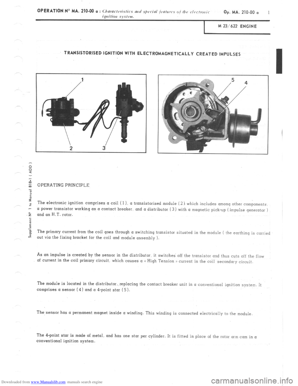
TRANSISTORISED IGNITION WITH ELECTROMAGNETICALLY CREATED IMPULSES
$ OPERATING PRINCIPLE
?
:
I
,D The electronic ignition comprises a coil ( 1 1. (I transistorised module ( 2) which includes among other components.
-
.f a power transistor working as a contact breaker.
and a distributor (3 1 with a magnetic pick-up ( impulse generator )
and an H.T. rotor.
;
ii
:
F The primary current from the coil goes through a switching transistor situated in the module ( the earthing is carried
“7
out via the fixing bracket for the coil mrd module assembly ).
As an impulse is created by the sensor in the distributor. it switches off the transistor and thus cuts off the flow
of current in the coil primhry circuit. which causes a (< High Tension 1) current in the coil secondary circuit.
The module is located in the distributor..replocinq the contact breaker unit in a conventional ignition system. It
comprises a sensor (4) and a 4-point star ( 5 ).
The,sensor has a permanent moqnet inside a winding. This windinq is connected electrically to the module
I
/
The 4-point star is made of metal. and has one star per cylinder. It is fitted in place of the rotor mm cam in (I
conventional ignition system.
Page 155 of 394

Downloaded from www.Manualslib.com manuals search engine CHARACTERISTICS
ENGINE REF.
........................................................................................... ........................ M 23/ 622
DISTRIBUTOR DUCELLIER ..................................................................................................................
Reference ..................................................................................................................... 525 100 A
Direction of rotation ( seen from drive end ) . .................................................................
Anti-clockwise
Star point gap ( between star point and sensor ) .............................................................. 0.3 to 0.5 mm
Angular positioning of star points ( symmetry of signal ) to within ........... ... ... ....... ..... 1” max.
Resistance of module 960 to 1140 fi .................................................................................................. Centrifugal
advance curve identification mark ................................. . ..................... LA 5
Vacuum advance correction
curve identification mark : ..................................................
LA 3 Static advance
: 10” engine flywheel . .’ Strobe setting
: 25’ at 2500 rpm SPARK PLUGS
Spark plug gap ................. ....
.................... ................... ....... 0.6 to 0.7 mm
......................... .........
Tightening torque ( cylinder head cold ) ....................................................................
2 to 2.5 daNm
( spl,(,c,)’ //T(, /hrc,nc/ /ig/T//>f cc,i//T H ,VO J~/,N/) )) ) ...................................................... (14.5 to 18 ft.lb )
I IGNITION COIL ‘AND TRANSISTORISED MODULE ASSEMBLY
I
Manufacturer ...............
................... ........ .............. .............. .......
AC - DELCO
...........................
Reference N” 210
....................................................... ...
....................................................
Resistance of coil primary circuit ( at 205 C ) ............................................................ 0.48 - 0.61 R
Resistance of coil secondary circuit ( at 20” C ) ......................................................... 8500 to 10500 fl H.T. LEADS
Description of leads Length in mm
Coil to distributor ....................... 1040 to 1050 mm
Cylinder N” 1 ............................ 440 to 450 mm
Cylinder N” 2 ............................. 520 to 530 mm
Cylinder N” 3 ................................ 780 to 790 mm
Cylinder No 4 850 to 860 mm
............................ Re:;istance of leads ( at 20L C )
I
1120 to 1765 (1
480 to 780 Q
530 to s95 Q
825 to 1335 Q
900 to 1445 R
Page 160 of 394

Downloaded from www.Manualslib.com manuals search engine OPERATION No MA. 210.0 : c l~vritis,e nvrl
Provisionally position support plate (2 1 and
gently tighten nut ( 1 )
c) Switch on ignition
Connect a test lamp to earth and to the G RUP B)
terminal of the ignition coil.
Turn the distributor until the exact moment
when the indicator lamp liqhts up.
At this point the distributor is al the static
advance point.
Switch off the ignition.
Tighten nut ( 1 ) from 19 to 21 mN ( 1.9 to
2.1 m kq 1 ( 13 l/2 to 15 ft.lb 1.
Fit distributor cap and secure it
Fit sparking plug in cylinder No 1 2. Checking the ignition timing using a stroboscopic
Imp or (I test-bench
( See chapter I,, page 1 i.