1982 CHEVROLET CAMARO transmission
[x] Cancel search: transmissionPage 451 of 875

GM – CAMARO 1982-1992 – Repair Guide (Checked by WxMax) 451
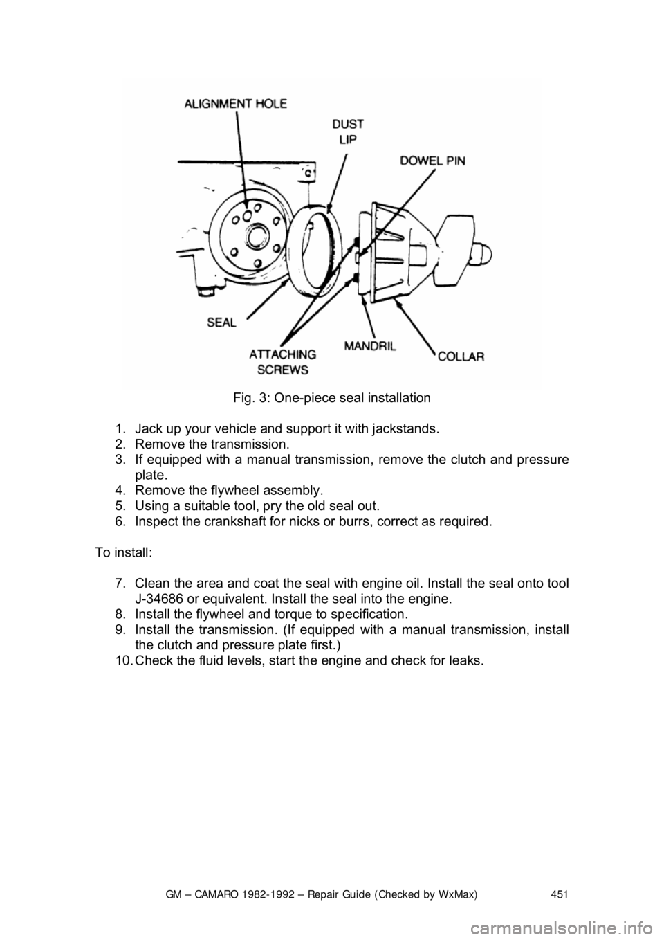
Fig. 3: One-piece seal installation
1. Jack up your vehicle and support it with jackstands.
2. Remove the transmission.
3. If equipped with a manual transmission, remove the clutch and pressure
plate.
4. Remove the flywheel assembly.
5. Using a suitable tool, pry the old seal out.
6. Inspect the crankshaft for nicks or burrs, correct as required.
To install: 7. Clean the area and coat the seal with eng ine oil. Install the seal onto tool
J-34686 or equivalent. Install the seal into the engine.
8. Install the flywheel and torque to specification.
9. Install the transmission. (If equipped with a manual transmission, install
the clutch and pressure plate first.)
10. Check the fluid levels, star t the engine and check for leaks.
Page 456 of 875

GM – CAMARO 1982-1992 – Repair Guide (Checked by WxMax) 456
2. Drain the engine oil and remove the oil pan.
3. Remove the rear main bearing cap.
4. Insert packing tool J-29114-2 or equi
valent, against 1 end of the seal in
the cylinder block. Drive the old seal gently into the groove until it is
packed tight. This will vary from
1/4 in. (6mm) to 3/4 in. (19mm) depending
on the amount of pack required.
5. Repeat the procedure on t he other end of the seal.
6. Measure the amount the seal wa s driven up on one side and add
1/16 in.
(1.6mm). Using a suitable cutting tool, cut that length from the old seal
removed from the rear main beari ng cap. Repeat the procedure for the
other side. Use the rear main bear ing cap as a holding fixture when
cutting the seal.
7. Install guide tool J-29114-1 or equi valent, onto the cylinder block.
8. Using the packing tool, work the shor t pieces cut in Step 6 into the guide
tool and then pack into the cylinder block. The guide tool and packing
tool are machined to provide a built in stop. Use this procedure for both
sides. It may help to use oil on the short pieces of the rope seal when \
packing them into the cylinder block.
9. Remove the guide tool.
10. Apply Loctite® 414 or equivalent, to the seal groove in the rear main
bearing cap. Within 1 minute, insert a new seal into the groove and push
into place with tool J-29590 until the seal is flush with the block. Cut the
excess seal material with a sharp cu tting tool at the bearing cap parting
line.
11. Apply a thin film of chassis grease to the rope se al. Apply a thin film of
RTV sealant on the bearing cap mati ng surface around the seal groove.
Use the sealer sparingly.
12. Plastigage® the rear main bea ring cap as outlined in MEASURING
REAR MAIN CLEARANCE in this section and check with specification. If
out of specification, check for fr ying of the rope seal which may be
causing the cap to not seat properly.
13. Install all remaining com ponents and inspect for leaks.
FLYWHEEL AND RING GEAR
REMOVAL & INSTALLATION
The ring gear is an integral part of the flywheel and is not replaceable.
1. Remove the transmission.
2. Remove the six bolts attaching t he flywheel to the crankshaft flange.
Remove the flywheel.
3. Inspect the flywheel for cracks, and inspect the ring gear for burrs or
worn teeth. Replace the flywheel if any damage is apparent. Remove
burrs with a mill file.
4. Install the flywheel. Th e flywheel will only attach to the crankshaft in one
position, as the bolt holes are unevenly spaced. Install the bolts and
torque to specification. Tighten bolts in crisscross pattern.
Page 492 of 875

GM – CAMARO 1982-1992 – Repair Guide (Checked by WxMax) 492
It is always recommended that you remo
ve any cylinder ridges before removing
the piston and connecting rod assemblies . If you know that new pistons are
going to be installed and the engine bl ock will be bored oversize, you may be
able to forego this step. However, some ridges may actually prevent the
assemblies from being remove d, necessitating its removal.
There are several different types of ridge reamers on the market, none of which
are inexpensive. Unless a great deal of engine rebuild ing is anticipated, borrow
or rent a reamer.
1. Turn the crankshaft until the piston is at the bottom of its travel.
2. Cover the head of the piston with a rag.
3. Follow the tool manufacturers in structions and cut away the ridge,
exercising extreme care to avoid cutting too deeply.
4. Remove the ridge reamer, the r ag and as many of the cuttings as
possible. Continue until all of the cylinder ridges have been removed.
DISASSEMBLY
The engine disassembly instructions fo llowing assume that you have the engine
mounted on an engine stand. If not, it is easiest to disassemble the engine on a
bench or the floor with it resting on t he bellhousing or transmission mounting
surface. You must be able to access the connecting rod fasteners and turn the
crankshaft during disassembly. Also, all en gine covers (timing, front, side, oil
pan, whatever) should have already been removed. Engines which are seized
or locked up may not be able to be co mpletely disassembled, and a core
(salvage yard) engine should be purchased.
If not done during the cylinder head removal, remove the pushrods and li\
fters,
keeping them in order for assembly. Remove the timing gears and/or timing
chain assembly, then remove the oil pu mp drive assembly and withdraw the
camshaft from the engine block. Remove the oil pick-up and pump assembly. If
equipped, remove any balanc e or auxiliary shafts. If necessary, remove the
cylinder ridge from the top of the bore. See the cylinder ridge removal
procedure earlier in this section.
Rotate the engine over so that the cr ankshaft is exposed. Use a number punch
or scribe and mark each connecting rod wit h its respective cylinder number. The
cylinder closest to the front of t he engine is always number 1. However,
depending on the engine placemen t, the front of the engine could either be the
flywheel or damper/pulley end. Generally the front of the engine faces the front
of the vehicle. Use a number punch or scribe and also mark the main bearing
caps from front to rear wit h the front most cap being nu mber 1 (if there are five
caps, mark them 1 through 5, front to rear).
Page 581 of 875

GM – CAMARO 1982-1992 – Repair Guide (Checked by WxMax) 581
Fig. 1: Coolant temperature sensor. The in take air temperature sensor is similar
in appearance
IDLE AIR CONTROL (IAC) VALVE
OPERATION
Engine idle speeds are controlled by the ECM through the IAC valve mounted
on the throttle body. The ECM sends volt age pulses to the IAC motor windings
causing the IAC motor shaft and pintle to move IN or OUT a given distance
(number of steps) for each pulse (called counts). The movement of the pintle
controls the airflow around the throttle plat e, which in turn, controls engine idle
speed. IAC valve pintle position counts ca n be observed using a scan tool. Zero
counts correspond to a fully closed passage, while 140 counts or more
corresponds to full flow.
Idle speed can be categorized in 2 ways : actual (controlled) idle speed and
minimum idle speed. Contro lled idle speed is obtained by the ECM positioning
the IAC valve pintle. Resulting idle speed is determined by total air fl\
ow
(IAC/passage + PCV + throttle valve + ca librated vacuum leaks). Controlled idle
speed is specified at normal operating c onditions, which consists of engine
coolant at normal operating temper ature, air conditioning compressor OFF,
manual transmission in neutral or automatic transmission in D.
Minimum idle air speed is set at t he factory with a stop screw. This setting
allows a certain amount of air to bypas s the throttle valves regardless of IAC
valve pintle positioning. A co mbination of this air flow and IAC pintle positioning
allows the ECM to control engine idle speed. During normal engine idle
operation, the IAC valve pintle is positioned a calibrated number of steps
(counts) from the seat. No adjustment is required during routine maintenance.
Tampering with the minimum idle speed adjustment may result in premature
failure of the IAC valve or imprope rly controlled engine idle operation.
Page 582 of 875

GM – CAMARO 1982-1992 – Repair Guide (Checked by WxMax) 582
REMOVAL & INSTALLATION
On some models it may be necessary
to remove the air inlet assembly.
1. Disconnect the negative battery cable. Disconnect the IAC valve
electrical wiring.
2. Remove the IAC valve by performing the following: a. On thread-mounted units, use a 1
1/4 inch (32mm) wrench.
b. On flange-mounted units, remove the mounting screw assemblies.
3. Remove the IAC valve ga sket or O-ring and discard.
To install: 4. Clean the mounting surfaces by performing the following:
a. If servicing a thread-mounted valve, remove the old gasket material from the surf ace of the throttle body to ensure proper
sealing of the new gasket.
b. If servicing a flange-mounted valve, clean the IAC valve surfaces on the throttle body to assure pr oper seal of the new O-ring and
contact of the IAC valve flange.
5. If installing a new IAC valve, meas ure the distance between the tip of the
IAC valve pintle and the mounting flange. If the distance is greater than
1.102 inch (28mm), use finger pressure to slowly retract the pintle. The
force required to retract the pintle of a new valve will not cause damage
to the valve. If reinstalling the origin al IAC valve, do not attempt to adjust
the pintle in this manner.
6. Install the IAC valve into the thro ttle body by performing the following:
a. With thread-mounted valves, in stall with a new gasket. Using a
1
1/4 inch (32mm) wrench, tighten to 13 ft. lbs. (18 Nm).
b. With flange-mounted valves, lubricate a new O-ring with
transmission fluid and install on the IAC valve. Install the IAC
valve to the throttle body. Inst all the mounting screws using a
suitable thread locking compound. Tight en to 28 inch lbs. (3 Nm).
7. Connect the IAC valve electrical wiring.
8. Connect the negative battery cable.
9. No physical adjustment of the IAC valve assembly is required after installation. Reset the IAC valve pintle position by performing the
following:
a. Depress the accelerator pedal slightly.
b. Start the engine and run for 5 seconds.
c. Turn the ignition switch to the OFF position for 10 seconds.
d. Restart the engine and check for proper idle operation.
Page 593 of 875

GM – CAMARO 1982-1992 – Repair Guide (Checked by WxMax) 593
REMOVAL & INSTALLATION
1. Disconnect the negative battery cable.
2. Drain the engine coolant.
3. Raise and properly support the vehicle.
4. Disconnect the knock sensor wiring harness.
5. Remove the knock sensor from the engine block.
CAUTION - The knock sensor is mounted in the engine block cooling passage.
Engine coolant in the block will dr ain when the sensor is removed.
6. Installation is the reverse of remova l. Tighten the sensor to 14 ft. lbs (19
Nm).
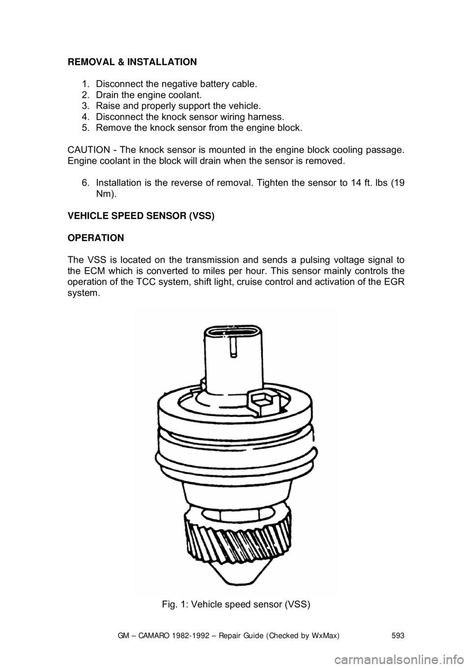
VEHICLE SPEED SENSOR (VSS)
OPERATION
The VSS is located on the transmission and sends a pulsing voltage signal to
the ECM which is converted to miles per hour. This sensor mainly controls the
operation of the TCC system, shift light, cr uise control and activation of the EGR
system.
Fig. 1: Vehicle speed sensor (VSS)
Page 594 of 875

GM – CAMARO 1982-1992 – Repair Guide (Checked by WxMax) 594
REMOVAL & INSTALLATION
1. Disconnect the negative battery cable.
2. Raise and safely support the vehicle.
3. Disconnect the VSS electrical wiring.
4. Remove the retaining bolt.
5. Have a clean container to catch the transmission fluid and remove the
VSS.
6. Remove and discard the O-ring.
To install: 7. Lubricate a new O-ring with a thin f ilm of transmission fluid. Install the O-
ring and VSS.
8. Install the retaining bolt.
9. Connect the electrical wiring.
10. Lower the vehicle.
11. Connect the negative battery cable.
12. Refill transmission to proper level.
TROUBLE CODES
SELF DIAGNOSTICS
READING CODES
The following procedure applies to mode ls with the 12 pin diagnostic connector
only.
1. Turn the ignition switch OFF. Locate the Assembly Line Diagnostic Link
(ALDL), usually under the instrument panel. It may be within a plastic
cover or housing labeled DIAGNOSTIC CONNECTOR. This link is used
to communicate with the ECM.
2. Use a small jumper wire to connect Terminal B of the ALDL to Terminal
A. As the ALDL connector is viewed from the front, Terminal A is on the
extreme right of the upper row; Terminal B is second from the right on
the upper row.
3. After the terminals are connected, turn the ignition switch to the ON
position but do not start the engine. T he dash warning lamp should begin
to flash Code 12. The code will disp lay as one flash, a pause and two
flashes. Code 12 is not a fault code. It is used as a system
acknowledgment or handshake code; its presence indicates that the
ECM can communicate as requested. Code 12 is used to begin every
diagnostic sequence.
4. After Code 12 has been transmitted 3 times, the fault codes, if any, will
each be flashed in the same manner th ree times. The codes are stored
and transmitted in numeric order from lowest to highest.
The order of codes in the memory does not indicate the order of occurrence.
Page 623 of 875

GM – CAMARO 1982-1992 – Repair Guide (Checked by WxMax) 623
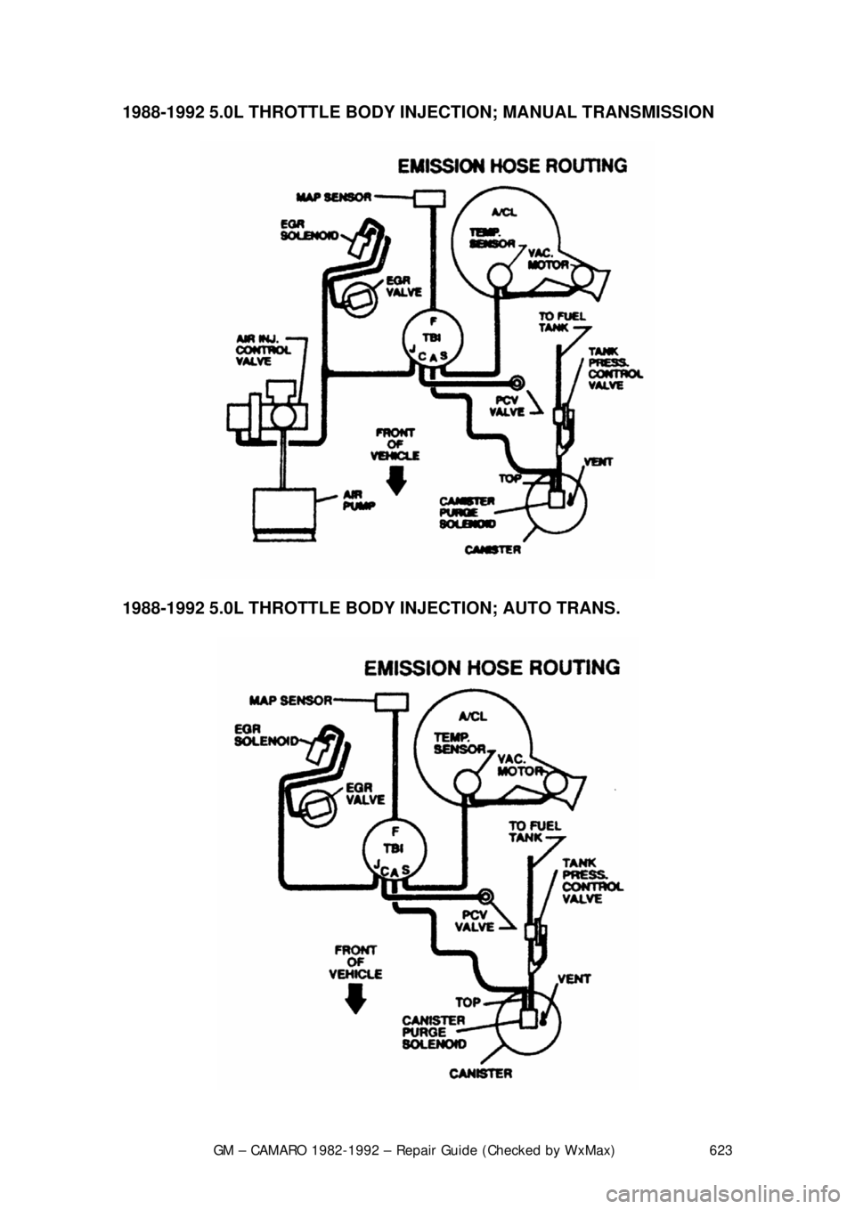
1988-1992 5.0L THROTTLE BODY INJECT
ION; MANUAL TRANSMISSION
1988-1992 5.0L THROTTLE BODY INJECTION; AUTO TRANS.