1982 CHEVROLET CAMARO check engine light
[x] Cancel search: check engine lightPage 660 of 875

GM – CAMARO 1982-1992 – Repair Guide (Checked by WxMax) 660
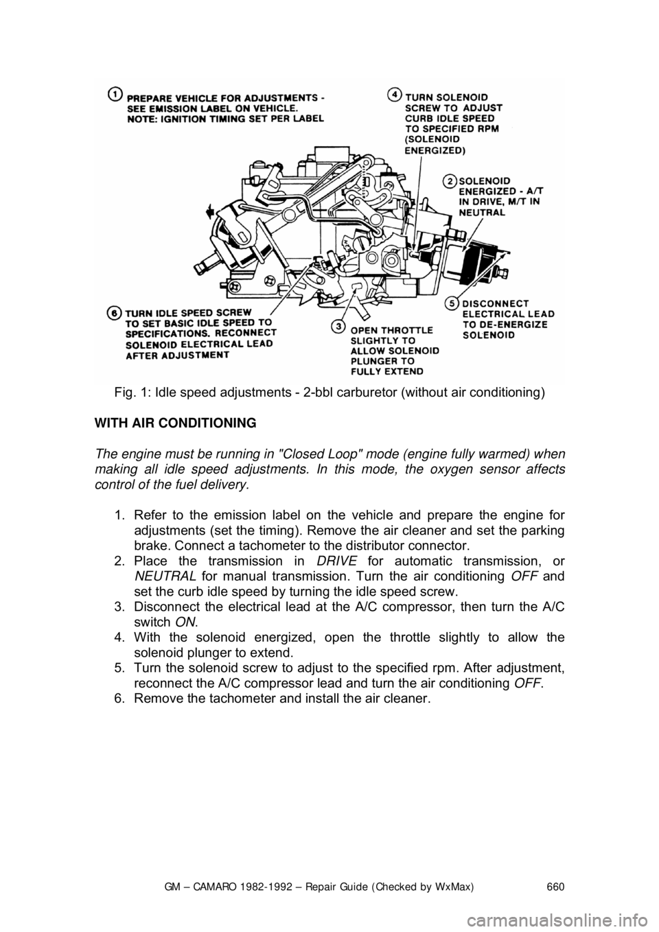
Fig. 1: Idle speed adjustm ents - 2-bbl carburetor (without air conditioning)
WITH AIR CONDITIONING
The engine must be running in "Closed Loop" mode (engine fully warmed) when
making all idle speed adjustments. In this mode, the oxygen sensor affects
control of the fuel delivery.
1. Refer to the emission label on the vehicle and prepare the engine for
adjustments (set the timing). Remove the air cleaner and set the parking
brake. Connect a tachometer to the distributor connector.
2. Place the transmission in DRIVE for automatic transmission, or
NEUTRAL for manual transmission. Tu rn the air conditioning OFF and
set the curb idle speed by turning the idle speed screw.
3. Disconnect the electrical lead at the A/C compressor, then turn the A/C
switch ON.
4. With the solenoid e nergized, open the throttle slightly to allow the
solenoid plunger to extend.
5. Turn the solenoid screw to adjust to the specified rpm. After adjustment,
reconnect the A/C compressor lead and turn the air conditioning OFF.
6. Remove the tachometer and install the air cleaner.
Page 670 of 875

GM – CAMARO 1982-1992 – Repair Guide (Checked by WxMax) 670
the idle speed or mixture,
adjust the idle and mixture again when you are
finished.
Before you make any carburetor adjustment s make sure that the engine is in
tune. Many problems which are thought to be carburetor related can be traced
to an engine which is simply out-of-tune. Any trouble in these areas will have
symptoms like those of carburetor problems.
ADJUSTMENTS
FAST IDLE
ROCHESTER E2SE 1. Refer to the emission label and pr epare the vehicle for adjustment.
2. Place the fast idle screw on the highest step of the fast idle cam.
3. Turn the fast idle screw to obtain the fast idle speed.
ROCHESTER E4ME AND E4MC
The fast idle adjustment must be perform ed according to the directions of the
emissions label.
FLOAT AND FUEL LEVEL
ROCHESTER E2SE
1. Remove the air horn and gasket.
2. While holding the retainer in place, push the float down lightly against the
needle.
3. Place a measuring gauge on the float at the farthest point from the float
hinge.
4. To adjust, remove the float and bend the arm up or down. Also check the
float alignment.
5. Install the air horn and gasket.
Page 688 of 875

GM – CAMARO 1982-1992 – Repair Guide (Checked by WxMax) 688
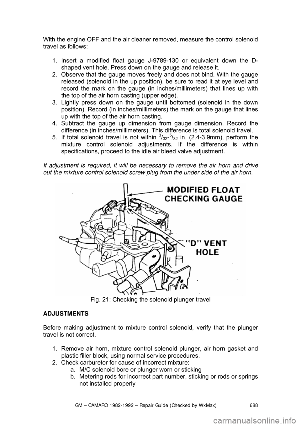
With the engine OFF and the air cleaner re
moved, measure the control solenoid
travel as follows:
1. Insert a modified float gauge J- 9789-130 or equivalent down the D-
shaped vent hole. Press down on the gauge and release it.
2. Observe that the gauge moves freel y and does not bind. With the gauge
released (solenoid in the up position), be sure to read it at eye level and
record the mark on the gauge (in inc hes/millimeters) that lines up with
the top of the air hor n casting (upper edge).
3. Lightly press down on the gauge until bottomed (solenoid in the down
position). Record (in inches/millimeters) the mark on the gauge that lines
up with the top of the air horn casting.
4. Subtract the gauge up dimension from gauge dimension. Record the
difference (in inches/millimet ers). This difference is total solenoid travel.
5. If total solenoid travel is not within
3/32-5/32 in. (2.4-3.9mm), perform the
mixture control solenoid adjustment s. If the difference is within
specifications, proceed to the id le air bleed valve adjustment.
If adjustment is required, it will be necessary to remove the air horn and drive
out the mixture control solenoid screw pl ug from the under side of the air horn.
Fig. 21: Checking the solenoid plunger travel
ADJUSTMENTS
Before making adjustment to mixture cont rol solenoid, verify that the plunger
travel is not correct.
1. Remove air horn, mixture control solenoid plunger, air horn gasket and
plastic filler block, using normal service procedures.
2. Check carburetor for caus e of incorrect mixture:
a. M/C solenoid bore or plunger worn or sticking
b. Metering rods for incorrect part number, sticking or rods or springs
not installed properly
Page 694 of 875

GM – CAMARO 1982-1992 – Repair Guide (Checked by WxMax) 694
IDLE MIXTURE
E2SE CARBURETORS
1. Remove the carburet or from the engine.
2. Remove the plugs coveri ng the idle mixture needles.
3. Turn the mixture needle in until slight ly seated, then back it out 4 turns.
4. If the plug in the air horn coveri ng the idle air bleed has been removed,
replace the air horn. If the plug is still in place, do not remove it.
5. Remove the vent stack screen a ssembly to gain access to the lean
mixture screw.
6. Using tool J-28696-10 or equivalent, turn the lean mixture screw in until
lightly seated, then back out 2
1/2 turns.
7. Install the carburetor on the engine.
8. Disconnect the bowl vent line at the carburetor.
9. Disconnect the EGR hos e and canister purge hose at the carburetor.
Cap the ports on t he carburetor.
10. Find the hose from port D of the carburetor to the temperature sensor
and secondary vacuum break thermal vacuum switch. Disconnect and
plug the vacuum hose going to the air cleaner.
11. Connect the positive lead of a dwell me ter to the mixture control solenoid
test lead (green connector). Connect the other lead to ground. Set the
meter to the 6 cylinder position.
12. Run the engine on the high step of the fast idle cam until the cooling fan
starts to cycle.
13. Run the engine at 3,0 00 rpm and adjust the lean mixture screw slowly.
Allow the reading to stabilize, obtain an average dwell of 35 degrees. It is
normal for the dwell to vary in a narrow range.
14. Return to idle.
15. Adjust the idle mixt ure screw to obtain an av erage dwell of 25 degrees.
Allow time for the reading to stabilize.
16. Run the engine at 3,000 rpm and not e the dwell reading. It should be
varying with an average reading of 35 degrees. If it does not, repeat the
earlier steps.
Page 695 of 875

GM – CAMARO 1982-1992 – Repair Guide (Checked by WxMax) 695
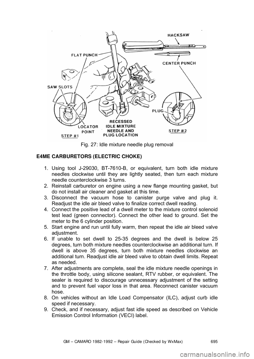
Fig. 27: Idle mixture needle plug removal
E4ME CARBURETORS (ELECTRIC CHOKE) 1. Using tool J-29030, BT-7610-B, or equivalent, turn both idle mixture
needles clockwise until they are lightly seated, then turn each mixture
needle counterclockwise 3 turns.
2. Reinstall carburetor on engine using a new flange mounting gasket, but
do not install air cleaner and gasket at this time.
3. Disconnect the vacuum hose to canister purge valve and plug it.
Readjust the idle air bleed valve to finalize correct dwell reading.
4. Connect the positive lead of a dwell me ter to the mixture control solenoid
test lead (green connector). Connect the other lead to ground. Set the
meter to the 6 cylinder position.
5. Start engine and run unt il fully warm, then repeat the idle air bleed valve
adjustment.
6. If unable to set dwell to 25-35 degrees and the dwell is below 25
degrees, turn both mixture needles counter clockwise an additional turn. If
dwell is above 35 degrees, turn both mixture needles clockwise an
additional turn. Readjust idle air bleed valve to obtain dwell limits. Repeat
as needed.
7. After adjustments are complete, seal the idle mixture needle openings in
the throttle body, using silicone sealant, RTV rubber, or equivalent. The
sealer is required to discourage unnecessary adjus tment of the setting
and to prevent fuel vapor loss in that area. Reconnect canister vacuum
hose.
8. On vehicles without an Idle Load Co mpensator (ILC), adjust curb idle
speed if necessary.
9. Check, and if necessary, adjust fa st idle speed as described on Vehicle
Emission Control Information (VECI) label.
Page 696 of 875

GM – CAMARO 1982-1992 – Repair Guide (Checked by WxMax) 696
Fig. 28: Lean mixture and idle mixture screw adjustment
E4MC CARBURETOR (HOT AIR CHOKE) 1. Using tool J-29030-B, BT-7610-B, or equivalent, turn each idle mixture
needle clockwise until lightly seated, then turn each mixture needle
counterclockwise 3 turns.
2. Reinstall carburetor on engine, using a new flange mounting gasket, but
do not install air cleaner or gasket at this time.
3. Disconnect vacuum hose to c anister purge valve and plug it.
4. Connect the positive lead of a dwell me ter to the mixture control solenoid
test lead (green connector). Connect the other lead to ground. Set the
meter to the 6 cylinder position.
5. Start engine and allow it to reac h normal operating temperature.
6. While idling in D ( N for manual transmission), adjust both mixture
needles equally, in
1/8 turn increments, until dwell reading varies within
the 25-35 degree range, attempting to be as close to 30 degrees as
possible.
7. If reading is too low, turn mixtur e needles counterclockwise. If reading is
too high, turn mixture needl es clockwise. Allow time for dwell reading to
stabilize after each adjustment.
After adjustments are complete, seal t he idle mixture needle openings in the
throttle body, using silicone sealant, RTV rubber, or equivalent. The sealer is
required to discourage unnece ssary readjustment of the setting and prevent fuel
vapor loss in that area.
8. On vehicles without a carburetor -mounted Idle Load Compensator (ILC) ,
adjust curb idle speed if necessary.
Page 739 of 875

GM – CAMARO 1982-1992 – Repair Guide (Checked by WxMax) 739
3. Make sure the ignition switch has
been in the OFF position for at least 10
seconds and that all accessories are OFF.
4. Turn the ignition switch ON and the pump will run for about 2 seconds.
Note the system pressure with t he pump running, it should be between
40-47 psi.
The ignition switch may have to be cycled to the ON position more than once to
obtain maximum pressure. It is also norma l for the pressure to drop slightly
when the pump first stops, but it should then hold steady.
5. If the pressure is not as specified, verify that fuel pump operation is
heard in the tank.
6. If fuel pump operation is not heard, inspect the fuel pump relay and
wiring.
7. If fuel pump operation is heard, inspect the filter and lines for restriction.
8. Start the engine and make sure the pr essure decreases about 3-10 psi at
idle.
9. If fuel pressure does not decrease, inspect the fuel pressure regulator
and hose.
10. Disconnect the fuel pressure gauge.
THROTTLE BODY
REMOVAL & INSTALLATION 1. Disconnect the negative (-) battery c able and partially drain the radiator.
2. Remove the air inlet duct and unplug the IAC and TPS electrical connectors.
3. Label and disconnect the vacuum and coolant lines.
4. Disconnect the accelerator, thro ttle valve (transmission control) and
cruise control cables, as applicable.
5. Remove the throttle body attaching bolts, then separate the throttle body from the plenum.
6. Discard the gasket.
To install: 7. Install the throttle body to the plenum using a new gasket. Tighten the \
bolts to specification.
8. Engage the accelerator, throttle valve and cruise control cables, as
necessary. Make sure that the link ages do not hold the throttle open.
9. Connect the vacuum and coolant lines.
10. Install the air inlet duct and plug the IAC and TPS electrical connectors
into their sockets.
11. Connect the negative (-) battery cable and refill the radiator.
12. With the engine OFF, check to s ee that the accelerator pedal is free.
Depress the pedal to the floor and release.
Page 743 of 875

GM – CAMARO 1982-1992 – Repair Guide (Checked by WxMax) 743
MINIMUM IDLE SPEED
The minimum idle speed should onl
y be adjusted under two conditions:
If the throttle body has been replaced.
After every other possible cause for the in correct idle speed has been explored.
There are many possible causes for incorre ct idle speed, most of which require
a high level of diagnostic skill as well as expensive testing equipment. Check
the vehicle for vacuum leaks, incorrect valve or ignition timing, deposit
accumulation in the throttle bore or valve, sticking throttle linkage or bent throttle
valves. If the vehicle will still not idle pr operly after checking these areas, it
should be diagnosed by a professional.
1. Pierce the idle stop screw with an awl. Apply leverage to remove it.
2. Make sure the IAC valve is connect ed. Short the A and B terminals of the
ALDL connector together with a length of wire.
3. Turn the ignition to the ON positi on, but do not start the engine. Wait at
least 30 seconds before proceeding.
4. With the ignition ON, disconnect the IAC valve connector.
5. Separate the set-timing connector. Th is eliminates the possibility of
changes in engine speed due to variations of engine timing.
6. Start the engine and remove t he wire shorting the A and B terminals
together. It may be necessary to hold the throttle open slightly to prevent
the engine from stalling.
7. Allow the engine to reach no rmal operating temperature.
8. Adjust the idle speed to the following: a. 2.8L Engines - 450-550 rp m A/T or 550-650 rpm M/T
b. 3.1L Engines - Refer to the underhood emissions sticker
c. 5.0L and 5.7L TPI engines - 400-450 rpm.
If these figures differ from t hose on the underhood emissions
sticker, always follow the specifications on the emissions sticker.
9. Turn the ignition OFF and connect the IAC valve harness. On models up
to 1989, adjust the Throttle Position Sensor.
THROTTLE POSITION SENSOR (TPS) 1. Install three jumper wires betw een the TPS and the harness connector.
2. Use a digital voltmeter connected to terminals A and B of the TPS.
3. Turn the ignition switch ON , but do not start the engine.
4. Loosen the TPS attaching screws and adj ust the sensor to the following:
a. 2.8L Engines - 0.50-0.60 volts
b. 5.0L and 5.7L TPI Engines - 0.47-0.61 volts
5. Tighten the attaching screws, then check that the reading has not been
disturbed.
6. With the ignition OFF, remove the jumper wires. Reconnect the TPS
harness.