1982 CHEVROLET CAMARO radiator
[x] Cancel search: radiatorPage 440 of 875

GM – CAMARO 1982-1992 – Repair Guide (Checked by WxMax) 440
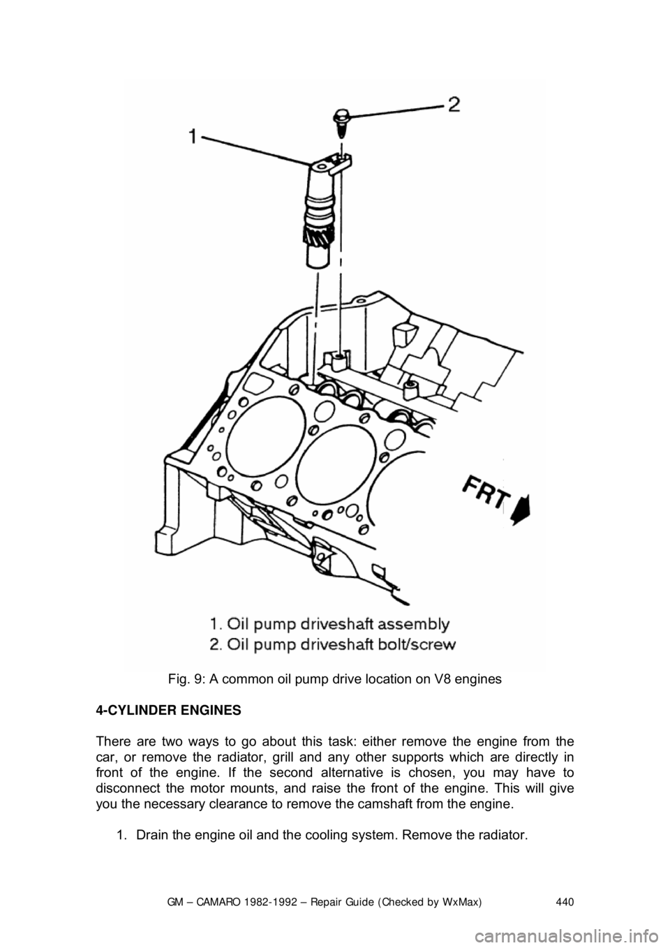
Fig. 9: A common oil pump drive location on V8 engines
4-CYLINDER ENGINES
There are two ways to go about this task: either remove the engine from the
car, or remove the radiator, grill and any other supports which are directly in
front of the engine. If the second altern ative is chosen, you may have to
disconnect the motor mounts, and raise t he front of the engine. This will give
you the necessary clearance to remove the camshaft from the engine.
1. Drain the engine oil an d the cooling system. Remove the radiator.
Page 442 of 875

GM – CAMARO 1982-1992 – Repair Guide (Checked by WxMax) 442
To install:
7. Lubricate all parts. Slide the ca mshaft onto the camshaft bearings.
8. Install the fuel pump and fuel pump pushrod.
9. Install the distributor and align all matchmarks.
10. Install the oil pump drive.
11. Install the valve lifters, pushrods and rocker arms.
12. Install the intake manifold and valve covers.
13. Install the timing and timing chain cover.
14. Install the radiator.
15. Fill the cooling syst em, start the engine and check for leaks.
BEARING
REMOVAL & INSTALLATION
It is recommended for a machine shop to perform these procedures.
To remove the camshaft bearings, the ca mshaft lifters, flywheel, rear camshaft
expansion plug, and cranks haft must be removed.
Camshaft bearings can be replaced wi th engine completely or partially
disassembled. To replace bearings without complete disassembly remove the
camshaft and crankshaft leaving cylinder heads attached and pistons in place.
Before removing crankshaft, tape threads of connecting rod bolts to prevent
damage to crankshaft. Fasten connecting rods against sides of engine so they
will not be in the way while replacing camshaft bearings.
If excessive wear is indicated, or if the engine is being completely rebuilt,
camshaft bearings should be replaced as follows: Drive the camshaft rear plug
from the block. Assemble the removal puller with its shoulder on the bearing to
be removed. Gradually tighten the puller nut until bearing is removed. Remove
remaining bearings, leaving the front and rear for last. To remove front and rear
bearings, reverse position of the tool, so as to pull the bearings in toward the
center of the block. Leave the tool in th is position, pilot the new front and rear
bearings on the installer, and pull them into position as follows:
• 4 cylinder engines: Ensure oil holes are properly aligned.
• V6 engines: Ensure the rear and intermediate bearing oil holes are
aligned between the 2 and 3 o'clock po sitions and the front bearing oil
holes are at 1:00 and between 2 and 3 o'clock positions.
• V8 engines: Ensure the No. 1 (f ront) camshaft bearing holes are an
equal distance from the 6 o'clock pos ition. The No. 2 through 4 inner
bearing holes must be posit ioned at the 5 o'clock position towards the left
side (drivers) of the engine, even wit h the bottom of the cylinder bore.
The No. 5 bearing oil holes must be positioned at 12 o'clock.
Return the tool to its original position and pull remaining bearings into position.
Page 465 of 875

GM – CAMARO 1982-1992 – Repair Guide (Checked by WxMax) 465
Fig. 12: Muffler hanger attachment
ENGINE RECONDITIONING DETE RMINING ENGINE CONDITION
Anything that generates heat and/or friction will eventually burn or wear out (i.e.
a light bulb generates heat, therefore its life span is limited). With this in mind, a
running engine generates trem endous amounts of both; friction is encountered
by the moving and rotating parts inside the engine and heat is created b\
y
friction and combustion of the fuel. Ho wever, the engine has systems designed
to help reduce the effects of heat and fr iction and provide added longevity. The
oiling system reduces the amount of fr iction encountered by the moving parts
inside the engine, while the cooling system reduces heat created by friction and
combustion. If either system is not main tained, a break-down will be inevitable.
Therefore, you can see how regular main tenance can affect the service life of
your vehicle. If you do not drain, flush and refill your cooling system at the
proper intervals, deposits will begin to accumulate in the radiator, thereby
reducing the amount of heat it can extrac t from the coolant. The same applies to
your oil and filter; if it is not changed often enoug h it becomes laden with
contaminates and is unable to properly lubricate the engine. This increases
friction and wear.
There are a number of methods for evaluat ing the condition of your engine. A
compression test can reveal the condition of your pistons, piston rings, cylinder
bores, head gasket(s), valves and valve seat s. An oil pressure test can warn
you of possible engine bearing, or oil pump failures. Excessive oil consumption,
evidence of oil in the engine air intake area and/or bluish smoke from the tail
pipe may indicate worn piston rings, worn valve guides and/or valve seals. As a
general rule, an engine that uses no more than one quart of oil every 1000
miles is in good condi tion. Engines that use one quart of oil or more in less than
1000 miles should first be checked for oil leaks. If any oil leaks are present,
have them fixed before dete rmining how much oil is consumed by the engine,
especially if blue smoke is not visible at the tail pipe.
COMPRESSION TEST
A noticeable lack of engine power, excessive oil consumption and/or poor fuel
mileage measured over an extended period are all indicators of internal engine
Page 467 of 875

GM – CAMARO 1982-1992 – Repair Guide (Checked by WxMax) 467
8. According to the tool manufacture
r's instructions, connect a remote
starting switch to the starting circuit.
9. With the ignition switch in the OFF position, use the remote starting
switch to crank the engine through at least five compression strokes
(approximately 5 seconds of cranking) and record the highest reading on
the gauge.
10. Repeat the test on each cylinder, cranking the engine approximately the
same number of compression stroke s and/or time as the first.
11. Compare the highest readi ngs from each cylinder to that of the others.
The indicated compression pre ssures are considered within
specifications if the lo west reading cylinder is within 75 percent of the
pressure recorded for the highest readi ng cylinder. For example, if your
highest reading cylinder pressure was 150 psi (1034 kPa), then 75
percent of that would be 113 psi (779 kPa). So the lowest reading
cylinder should be no less than 113 psi (779 kPa).
12. If a cylinder exhibits an unusually low compression reading, pour a
tablespoon of clean engine oil into the cylinder through the spark plug
hole and repeat the compression tes t. If the compression rises after
adding oil, it means that the cylinder's piston rings and/or cylinder bore
are damaged or worn. If the pressure re mains low, the valves may not be
seating properly (a valve job is needed), or the head gasket may be
blown near that cylinder. If compressi on in any two adjacent cylinders is
low, and if the addition of oil doesn' t help raise compression, there is
leakage past the head gasket. Oil and coolant in the combustion
chamber, combined with blue or const ant white smoke from the tail pipe,
are symptoms of this pr oblem. However, don't be alarmed by the normal
white smoke emitted from the tail pipe during engine warm-up or from
cold weather driving. There may be evidence of water droplets on the
engine dipstick and/or oil droplets in the cooling system if a head gasket
is blown.
OIL PRESSURE TEST
Check for proper oil pressu re at the sending unit passage with an externally
mounted mechanical oil pressure gauge (a s opposed to relying on a factory
installed dash-mounted gauge). A tachom eter may also be needed, as some
specifications may require running the engine at a specific rpm.
1. With the engine cold, locate and remo ve the oil pressure sending unit.
2. Following the manufacturer's inst ructions, connect a mechanical oil
pressure gauge and, if necessary, a tachometer to the engine.
3. Start the engine and allow it to idle.
4. Check the oil pressure reading when cold and record the number. You
may need to run the engine at a specified rpm, so check the
specifications chart located earlier in this section.
5. Run the engine until normal operati ng temperature is reached (upper
radiator hose will feel warm).
6. Check the oil pressure reading agai n with the engine hot and record the
number. Turn the engine OFF.
Page 513 of 875

GM – CAMARO 1982-1992 – Repair Guide (Checked by WxMax) 513
1. Connect the vehicle battery.
2. Start the engine. Keep y
our eye on your oil pressure indicator; if it does
not indicate oil pressure within 10 se conds of starting, turn the vehicle
off.
WARNING - Damage to the engine can result if it is allowed to run with no oil
pressure. Check the engine oil level to make sure that it is full. Check for any
leaks and if found, repair the leaks be fore continuing. If there is still no
indication of oil pressure, y ou may need to prime the system.
3. Confirm that there are no fluid leaks (oil or other).
4. Allow the engine to reach nor mal operating temperature (the upper
radiator hose will be hot to the touch).
5. If necessary, set the ignition timing.
6. Install any remaining components such as the air cleaner (if removed for
ignition timing) or body panels which were removed.
BREAKING IT IN
Make the first miles on the new engine , easy ones. Vary the speed but do not
accelerate hard. Most importantly, do not lug the engine, and avoid sustained
high speeds until at least 100 miles. Ch eck the engine oil and coolant levels
frequently. Expect the engine to use a littl e oil until the rings seat. Change the
oil and filter at 500 miles, 1500 mile s, then every 3000 miles past that.
KEEP IT MAINTAINED
Now that you have just gone through all of that hard work, keep yourself from
doing it all over again by thoroughly maintaining it. Not that you may not have
maintained it before, heck you c ould have had one to two hundred thousand
miles on it before doing this. However, you may have bought the vehicle used,
and the previous owner did not keep up on maintenance. Which is why you just
went through all of that hard work. See?
Page 690 of 875

GM – CAMARO 1982-1992 – Repair Guide (Checked by WxMax) 690
b. Install plug, with hollow end do
wn, over the rich mixture stop
screw access hole and drive plug into place so that the top of the
plug is
3/16 in. (4.7mm) below the surface of the air horn casting.
Plug must be installed to retain screw setting.
12. To check the M/C solenoid dwell, first disconnect vacuum line to the
canister purge valve and plug it. Ground diagnostic TEST terminal and
run engine until it is at normal operat ion temperature (upper radiator
hose hot) and in closed loop.
13. Check M/C dwell at 3000 rpm. If within 10-50 degrees, calibration is
complete. If higher than 50 degrees, chec k the carburetor for a cause of
rich condition. If below 10 degrees, look for a cause of lean engine
condition such as vacuum leaks. If none are found, check for the cause
of a lean carburetor.
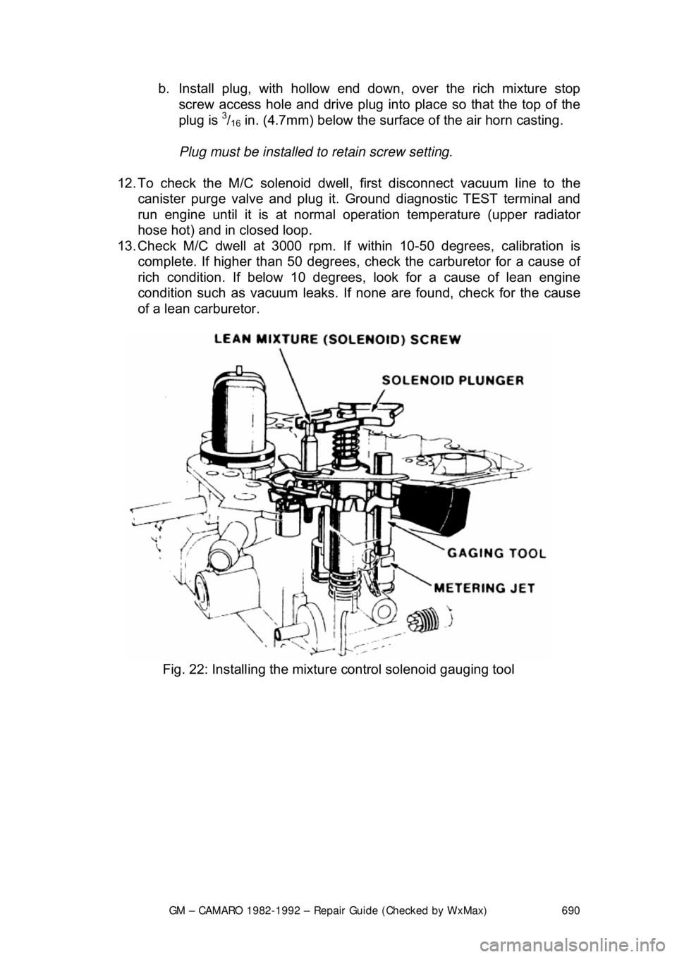
Fig. 22: Installing the mixture control solenoid gauging tool
Page 739 of 875

GM – CAMARO 1982-1992 – Repair Guide (Checked by WxMax) 739
3. Make sure the ignition switch has
been in the OFF position for at least 10
seconds and that all accessories are OFF.
4. Turn the ignition switch ON and the pump will run for about 2 seconds.
Note the system pressure with t he pump running, it should be between
40-47 psi.
The ignition switch may have to be cycled to the ON position more than once to
obtain maximum pressure. It is also norma l for the pressure to drop slightly
when the pump first stops, but it should then hold steady.
5. If the pressure is not as specified, verify that fuel pump operation is
heard in the tank.
6. If fuel pump operation is not heard, inspect the fuel pump relay and
wiring.
7. If fuel pump operation is heard, inspect the filter and lines for restriction.
8. Start the engine and make sure the pr essure decreases about 3-10 psi at
idle.
9. If fuel pressure does not decrease, inspect the fuel pressure regulator
and hose.
10. Disconnect the fuel pressure gauge.
THROTTLE BODY
REMOVAL & INSTALLATION 1. Disconnect the negative (-) battery c able and partially drain the radiator.
2. Remove the air inlet duct and unplug the IAC and TPS electrical connectors.
3. Label and disconnect the vacuum and coolant lines.
4. Disconnect the accelerator, thro ttle valve (transmission control) and
cruise control cables, as applicable.
5. Remove the throttle body attaching bolts, then separate the throttle body from the plenum.
6. Discard the gasket.
To install: 7. Install the throttle body to the plenum using a new gasket. Tighten the \
bolts to specification.
8. Engage the accelerator, throttle valve and cruise control cables, as
necessary. Make sure that the link ages do not hold the throttle open.
9. Connect the vacuum and coolant lines.
10. Install the air inlet duct and plug the IAC and TPS electrical connectors
into their sockets.
11. Connect the negative (-) battery cable and refill the radiator.
12. With the engine OFF, check to s ee that the accelerator pedal is free.
Depress the pedal to the floor and release.
Page 792 of 875

GM – CAMARO 1982-1992 – Repair Guide (Checked by WxMax) 792
The fluid level may be checked by obs
erving the fluid level marks of the
recovery tank. The leve l should be between the FULL HOT and FULL COLD
mark when the system is at normal operat ing temperature. When the engine is
cold, the fluid level should be above the FULL COLD mark on the reservoir. At
normal operating temperatures, t he level should be between the ADD and the
FULL marks. Only add coolant to bring the level to the FULL mark.
CAUTION - Should it be necessary to remove the radiator cap, make sure that
the system has had time to cool, reducing t he internal pressure. If the system is
opened while the engine is st ill hot, scalding fluid and steam may be blown out
under pressure.
DRAINING AND REFILLING
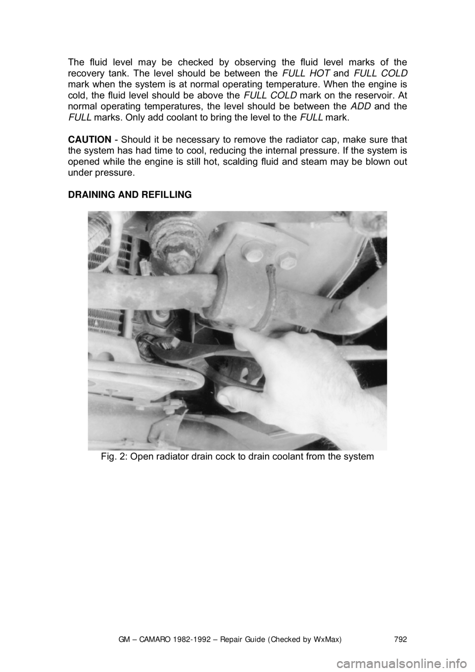
Fig. 2: Open radiator drain cock to drain coolant from the system