1982 CHEVROLET CAMARO engine coolant
[x] Cancel search: engine coolantPage 573 of 875

GM – CAMARO 1982-1992 – Repair Guide (Checked by WxMax) 573
7. Install the retaining bracket.
8. Connect the negative battery cable.
ELECTRONIC ENGINE CONTROLS
COMPUTER COMMAND CO NTROL (CCC) SYSTEM
The Computer Command Control (CCC) Sy stem is an electronically controlled
exhaust emission system that can m onitor and control a large number of
interrelated emission cont rol systems. It can monitor various engine/vehicle
operating conditions and then use this in formation to control multiple engine
related systems. The CCC syst em is thereby making constant adjustments to
maintain optimum vehicle performance und er all normal driving conditions while
at the same time allowing the catalyti c converter to effectively control the
emissions of HC, CO and NO
x.
OPERATION
The Electronic Control Module (ECM) is required to maintain the exhaust
emissions at acceptable le vels. The module is a sma ll, solid state computer
which receives signals from many source s and sensors; it uses these data to
make judgements about operating conditions and then control output signals to
the fuel and emission systems to ma tch the current requirements.
Inputs are received from m any sources to form a complete picture of engine
operating conditions. Some inputs are simp ly Yes or No messages, such as that
from the Park/Neutral switch; the vehicle is either in gear or in Park/Neutral;
there are no other choices. Other data is sent in quantitative input, such as
engine rpm or coolant temperature. T he ECM is pre-programmed to recognize
acceptable ranges or combinations of si gnals and control the outputs to control
emissions while providing good driv eability and economy. The ECM also
monitors some output circuits, making sure that the components function as
commanded. For proper engine oper ation, it is essential that all input and output
components function properly and comm unicate properly with the ECM.
Since the control module is programmed to recognize the presence and value
of electrical inputs, it will also note the lack of a signal or a radical change in
values. It will, for example, react to the loss of signal from the vehicle speed
sensor or note that engine coolant temperature has risen beyond acceptable
(programmed) limits. Once a fault is recognized, a numeric code is assigned
and held in memory. The SERVICE ENGIN E SOON Malfunction Indicator Lamp
(MIL), will illuminate to advise the operator that the system has detected a fault.
More than one code may be stored. Although not every engine uses every
code, possible codes range from 12-999. Additionally, the same code may carry
different meanings relative to each engine or engine family. For example, on the
3.3L (VIN N) engine, code 46 indicates a fault found in the power steering
pressure switch circuit. The same code on the 5.7L (VIN F) engine indicates a
fault in the VATS anti-theft system.
Page 580 of 875

GM – CAMARO 1982-1992 – Repair Guide (Checked by WxMax) 580
4. Spray a commercial solvent onto the sensor threads and allow it to soak
in for at least five minutes.
5. Carefully remove the sensor wit h a special oxygen sensor socket.
To install: 6. First coat the new sensor's th reads with GM anti-seize compound No.
5613695 or the equivalent. This is not a conventional anti-seize paste.
The use of a regular compound may el ectrically insulate the sensor,
rendering it inoperative. Y ou must coat the threads with an electrically
conductive anti-seize compound. Installati on torque is 30 ft. lbs. (41 Nm).
Do not overtighten.
7. Reconnect the electric al wiring. Be careful not to damage the electrical
pigtail. Check the sensor boot fo r proper fit and installation.
8. Reconnect the negative battery cable.
COOLANT TEMPERATURE SENSOR
OPERATION
Most engine functions are affected by the coolant temperature. Determining
whether the engine is hot or cold is largely dependent on the temperature of the
coolant. An accurate temperature signal to the ECM is supplied by the coolant
temperature sensor. The coolant temperatur e sensor is a thermistor mounted in
the engine coolant stream. A thermistor is an electrical device that varies its
resistance in relation to changes in temperature. Low coolant temperature
produces a high resistance and high coolant temperature produces low
resistance. The ECM supplies a signal of 5 volts to the coolant temperature
sensor through a resistor in the ECM and measures the voltage. The voltage
will be high when the engine is cold and low when the engine is hot.
REMOVAL & INSTALLATION
1. Disconnect the negative battery cable.
2. Drain the cooling system to an appropr iate and clean container for reuse.
3. Disconnect the electrical wiring fr om the coolant temperature sensor.
4. Remove the coolant temperature sensor.
To install: 5. Install the coolant temperature sensor.
6. Connect the electrical wiring.
7. Fill the cooling system.
8. Connect the negative battery cable.
9. Start the engine and check for leaks.
Page 581 of 875

GM – CAMARO 1982-1992 – Repair Guide (Checked by WxMax) 581
Fig. 1: Coolant temperature sensor. The in take air temperature sensor is similar
in appearance
IDLE AIR CONTROL (IAC) VALVE
OPERATION
Engine idle speeds are controlled by the ECM through the IAC valve mounted
on the throttle body. The ECM sends volt age pulses to the IAC motor windings
causing the IAC motor shaft and pintle to move IN or OUT a given distance
(number of steps) for each pulse (called counts). The movement of the pintle
controls the airflow around the throttle plat e, which in turn, controls engine idle
speed. IAC valve pintle position counts ca n be observed using a scan tool. Zero
counts correspond to a fully closed passage, while 140 counts or more
corresponds to full flow.
Idle speed can be categorized in 2 ways : actual (controlled) idle speed and
minimum idle speed. Contro lled idle speed is obtained by the ECM positioning
the IAC valve pintle. Resulting idle speed is determined by total air fl\
ow
(IAC/passage + PCV + throttle valve + ca librated vacuum leaks). Controlled idle
speed is specified at normal operating c onditions, which consists of engine
coolant at normal operating temper ature, air conditioning compressor OFF,
manual transmission in neutral or automatic transmission in D.
Minimum idle air speed is set at t he factory with a stop screw. This setting
allows a certain amount of air to bypas s the throttle valves regardless of IAC
valve pintle positioning. A co mbination of this air flow and IAC pintle positioning
allows the ECM to control engine idle speed. During normal engine idle
operation, the IAC valve pintle is positioned a calibrated number of steps
(counts) from the seat. No adjustment is required during routine maintenance.
Tampering with the minimum idle speed adjustment may result in premature
failure of the IAC valve or imprope rly controlled engine idle operation.
Page 593 of 875

GM – CAMARO 1982-1992 – Repair Guide (Checked by WxMax) 593
REMOVAL & INSTALLATION
1. Disconnect the negative battery cable.
2. Drain the engine coolant.
3. Raise and properly support the vehicle.
4. Disconnect the knock sensor wiring harness.
5. Remove the knock sensor from the engine block.
CAUTION - The knock sensor is mounted in the engine block cooling passage.
Engine coolant in the block will dr ain when the sensor is removed.
6. Installation is the reverse of remova l. Tighten the sensor to 14 ft. lbs (19
Nm).
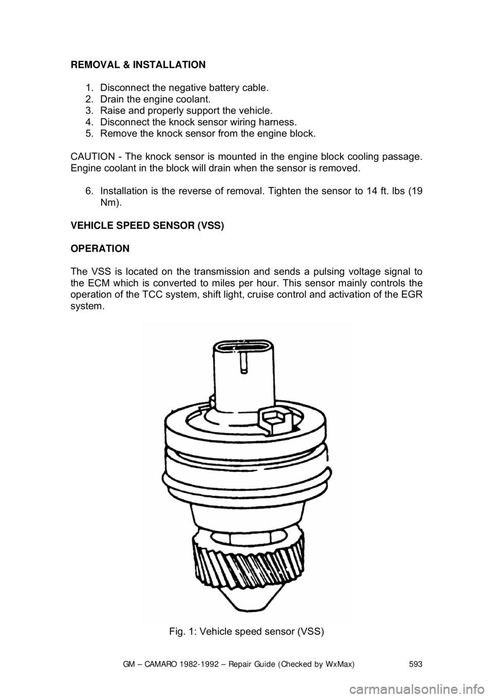
VEHICLE SPEED SENSOR (VSS)
OPERATION
The VSS is located on the transmission and sends a pulsing voltage signal to
the ECM which is converted to miles per hour. This sensor mainly controls the
operation of the TCC system, shift light, cr uise control and activation of the EGR
system.
Fig. 1: Vehicle speed sensor (VSS)
Page 736 of 875

GM – CAMARO 1982-1992 – Repair Guide (Checked by WxMax) 736
The mass air flow systems measure the
mass of air that is drawn into the
engine cylinders, rather than just the vo lume. The sensor contains a hot-wire
sensing unit, which is made up of an electronic balanced bridge network.
Whenever current is suppli ed to the sensor, the bridge is energized and the
sensing hot-wire is heated. As the air enter s the mass air flow sensor, it passes
over and cools the hot wire. When the hot wire is cooled, it's resistance changes
and additional current is needed to k eep the bridge network balanced. This
increase in current is sent to the computer as a voltage signal and is used to
calculate the mass of the incoming air. The ECM uses this information to\
determine the duration of fuel injection pulse, ignition timing and EGR operation.
The speed density systems calculate the volume of air moving through the
intake. The ECM establishes the speed fact or through a signal from the ignition
module. The Manifold or Intake Air Temperature (MAT/IAT) and the Engine
Coolant Temperature (ECT) sensors work together to assure that proper
temperature information gets to the ECM wh ile the Manifold Absolute Pressure
(MAP) sensor monitors the changes in m anifold pressure which results from
changes in engine loading. These three se nsors contribute to the density factor.
Together, these inputs (engine speed, coolant temperature sensor, etc ...) are
the major determinants of the air/fuel mixture delivered by the fuel injection
system.
The following engines and fuel managem ent systems are covered in this
section:
• 1985-1989 2.8L MPFI - Mass Air Flow
• 1990-1992 3.1L MPFI - Speed Density
• 1985-1989 5.0L and 5.7L TPI - Mass Air Flow
• 1990-1992 5.0L and 5.7L TPI - Speed Density
Relieving Fuel System Pressure
1. Disconnect the negative battery cable to prevent fuel discharge if the key
is accidentally turned to the RUN position.
2. Loosen the fuel filler cap to reliev e the tank pressure and do not tighten
until service has been completed.
3. Connect J-34730-1 fuel pressure gauge or equivalent, to the fuel
pressure test valve. Wrap a shop towel around the fitting while
connecting the gauge to prevent spillage.
4. Place the end of the bleed hose into a suitable container and open the
valve to relieve the fuel system pressure.
ELECTRIC FUEL PUMP
REMOVAL & INSTALLATION
The fuel pump is part of t he fuel sender assembly located inside the fuel tank.
Page 739 of 875

GM – CAMARO 1982-1992 – Repair Guide (Checked by WxMax) 739
3. Make sure the ignition switch has
been in the OFF position for at least 10
seconds and that all accessories are OFF.
4. Turn the ignition switch ON and the pump will run for about 2 seconds.
Note the system pressure with t he pump running, it should be between
40-47 psi.
The ignition switch may have to be cycled to the ON position more than once to
obtain maximum pressure. It is also norma l for the pressure to drop slightly
when the pump first stops, but it should then hold steady.
5. If the pressure is not as specified, verify that fuel pump operation is
heard in the tank.
6. If fuel pump operation is not heard, inspect the fuel pump relay and
wiring.
7. If fuel pump operation is heard, inspect the filter and lines for restriction.
8. Start the engine and make sure the pr essure decreases about 3-10 psi at
idle.
9. If fuel pressure does not decrease, inspect the fuel pressure regulator
and hose.
10. Disconnect the fuel pressure gauge.
THROTTLE BODY
REMOVAL & INSTALLATION 1. Disconnect the negative (-) battery c able and partially drain the radiator.
2. Remove the air inlet duct and unplug the IAC and TPS electrical connectors.
3. Label and disconnect the vacuum and coolant lines.
4. Disconnect the accelerator, thro ttle valve (transmission control) and
cruise control cables, as applicable.
5. Remove the throttle body attaching bolts, then separate the throttle body from the plenum.
6. Discard the gasket.
To install: 7. Install the throttle body to the plenum using a new gasket. Tighten the \
bolts to specification.
8. Engage the accelerator, throttle valve and cruise control cables, as
necessary. Make sure that the link ages do not hold the throttle open.
9. Connect the vacuum and coolant lines.
10. Install the air inlet duct and plug the IAC and TPS electrical connectors
into their sockets.
11. Connect the negative (-) battery cable and refill the radiator.
12. With the engine OFF, check to s ee that the accelerator pedal is free.
Depress the pedal to the floor and release.
Page 792 of 875

GM – CAMARO 1982-1992 – Repair Guide (Checked by WxMax) 792
The fluid level may be checked by obs
erving the fluid level marks of the
recovery tank. The leve l should be between the FULL HOT and FULL COLD
mark when the system is at normal operat ing temperature. When the engine is
cold, the fluid level should be above the FULL COLD mark on the reservoir. At
normal operating temperatures, t he level should be between the ADD and the
FULL marks. Only add coolant to bring the level to the FULL mark.
CAUTION - Should it be necessary to remove the radiator cap, make sure that
the system has had time to cool, reducing t he internal pressure. If the system is
opened while the engine is st ill hot, scalding fluid and steam may be blown out
under pressure.
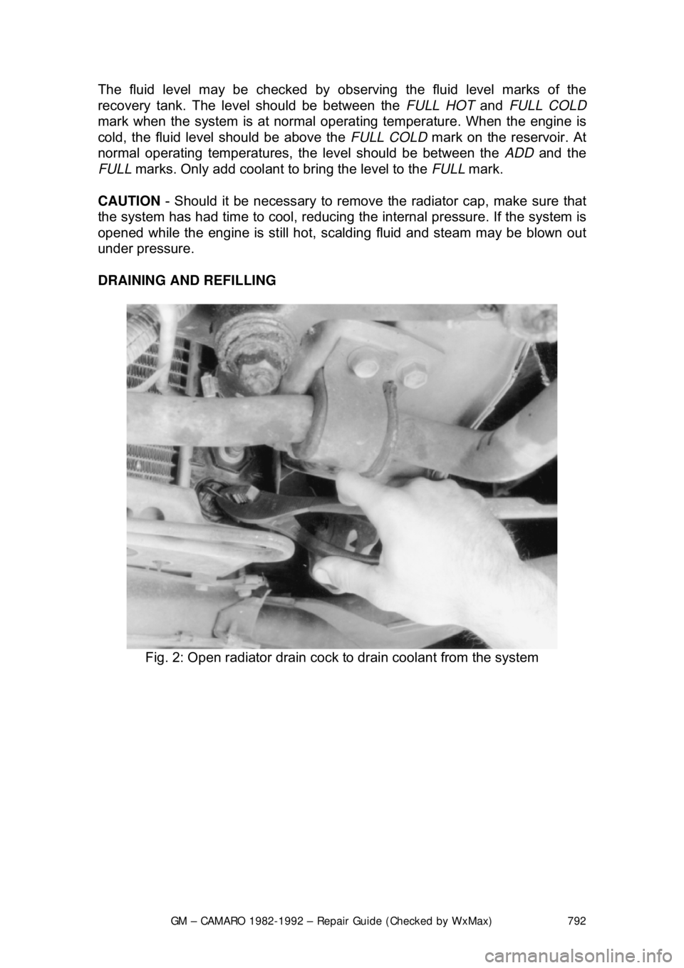
DRAINING AND REFILLING
Fig. 2: Open radiator drain cock to drain coolant from the system
Page 794 of 875

GM – CAMARO 1982-1992 – Repair Guide (Checked by WxMax) 794
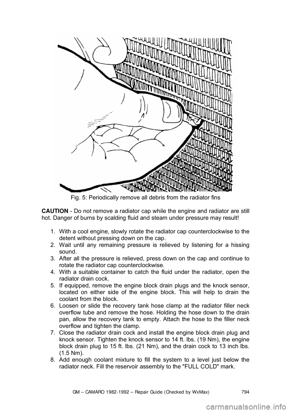
Fig. 5: Periodically remove all debris from the radiator fins
CAUTION - Do not remove a radiator cap wh ile the engine and radiator are still
hot. Danger of burns by scalding fluid and steam under pressure may result!
1. With a cool engine, slowly rotate t he radiator cap counterclockwise to the
detent without pressing down on the cap.
2. Wait until any remaini ng pressure is relieved by listening for a hissing
sound.
3. After all the pressure is relieved, press down on the cap and continue to
rotate the radiator cap counterclockwise.
4. With a suitable container to catc h the fluid under the radiator, open the
radiator drain cock.
5. If equipped, remove the engine blo ck drain plugs and the knock sensor,
located on either side of the engine block. This will help to drain the
coolant from the block.
6. Loosen or slide the recovery tank hos e clamp at the radiator filler neck
overflow tube and remove the hose. Holding the hose down to the drain
pan, allow the recovery tank to empty. Attach the hose to the filler neck
overflow and tighten the clamp.
7. Close the radiator drain cock and install the engine block drain plug and
knock sensor. Tighten the knock sensor to 14 ft. lbs. (19 Nm), the engine
block drain plug to 15 ft. lbs. (21 N m), and the drain cock to 13 inch lbs.
(1.5 Nm).
8. Add enough coolant mixture to fill the system to a level just below the
radiator neck. Fill the reservoir a ssembly to the "FULL COLD" mark.