1982 CHEVROLET CAMARO parking brake
[x] Cancel search: parking brakePage 124 of 875

GM – CAMARO 1982-1992 – Repair Guide (Checked by WxMax) 124
BRAKE LEVER
REMOVAL & INSTALLATION
1982-89 MODELS
1. Raise and safely support the vehicle.
2. Remove the adjusting nut
at the equalizer and remove the front cable from
the equalizer and bracket.
3. Lower the vehicle.
4. Remove the upper console and lower c onsole rear screws. Lift the rear of
the lower console to gain access to the parking brake control.
5. Remove the pin and retainer from t he control assembly and front cable.
6. Remove the cable and casing from the control assembly and bracket then
remove the cable and grommet from the vehicle. Remove the parking brake
lever mounting bolts and remove the assembly.
7. Installation is the reverse of t he removal procedure. Adjust the parking
brake.
1990-92 MODELS
1. Remove the carpet finish molding.
2. Remove the console assembly.
3. With the parking brake lever in the do wn position, rotate the arm toward the
front of the vehicle until a 3mm metal pen can be inserted into the hole.
Insert the metal pin into the hole, locking out the self adjuster.
4. Raise and safely support the vehicle.
5. Disconnect the rear cables from the equalizer.
6. Lower the vehicle.
7. Remove the barrel-shaped butt on from the adjuster track.
8. Remove the parking brake lever mounting bolts.
9. Remove the front cable and casing from the control assembly using a
fabricated parking brake cable retainer compressor tool.
10. Installation is the reverse of the removal procedure. Cycle the lever to set
the parking lever and cables in there proper location.
Page 211 of 875

GM – CAMARO 1982-1992 – Repair Guide (Checked by WxMax) 211
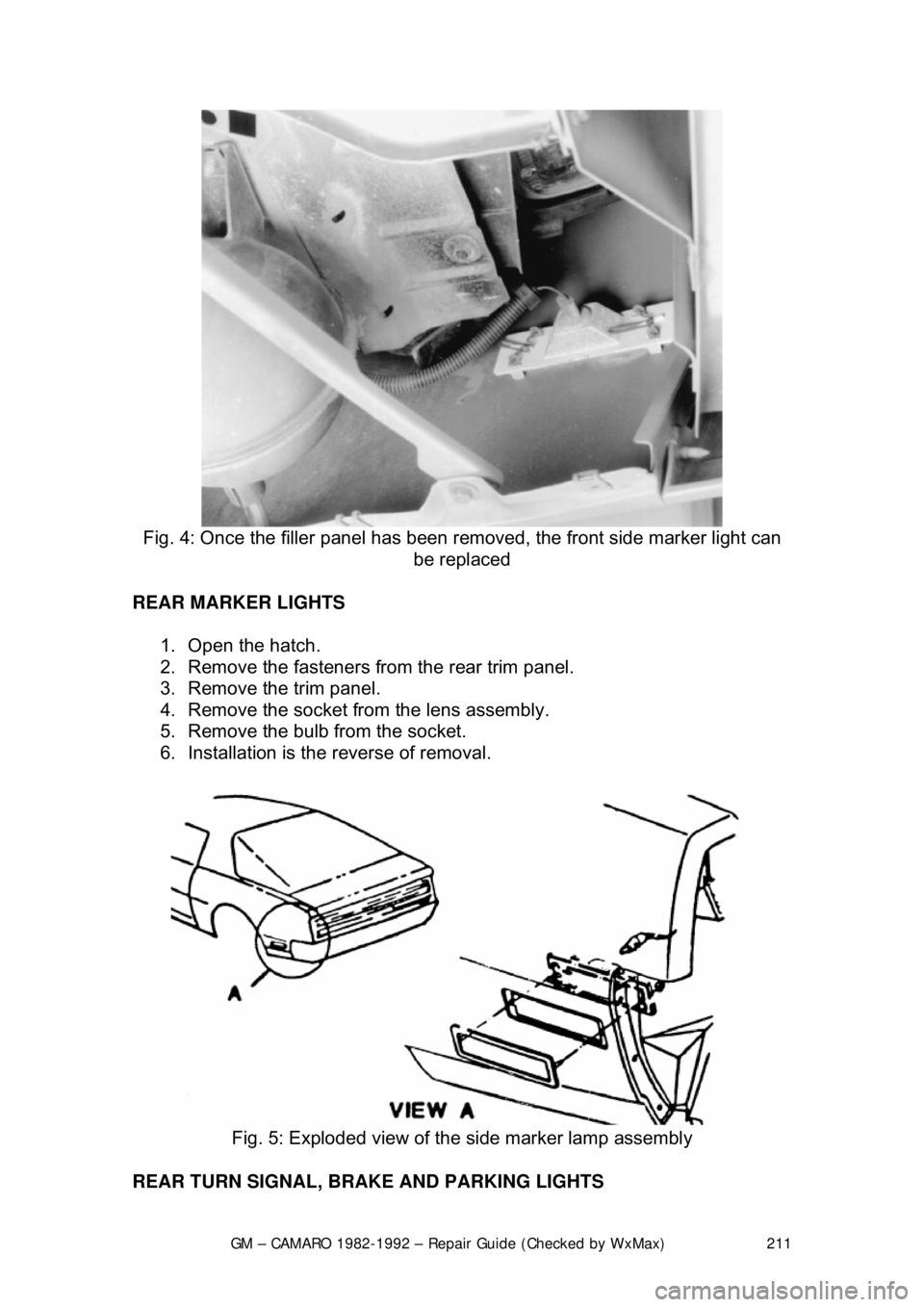
Fig. 4: Once the filler panel has been remo ved, the front side marker light can
be replaced
REAR MARKER LIGHTS 1. Open the hatch.
2. Remove the fasteners from the rear trim panel.
3. Remove the trim panel.
4. Remove the socket from the lens assembly.
5. Remove the bulb from the socket.
6. Installation is the reverse of removal.
Fig. 5: Exploded view of the side marker lamp assembly
REAR TURN SIGNAL, BRAKE AND PARKING LIGHTS
Page 659 of 875

GM – CAMARO 1982-1992 – Repair Guide (Checked by WxMax) 659
VALVE LASH
All models utilize a hydraulic valve lifter system to obtain zero lash. No periodic
adjustment is necessary. An initial adjustm
ent is required anytime that the lifters
are removed or the valve tr ain is disturbed. This procedure is covered in Engine
& Engine Overhaul .
IDLE SPEED AND MIXTURE ADJUSTMENTS
Mixture adjustments are factory set and sealed; no adjustment attempt should
be made, except by an aut horized GM dealer or reputable shop equipped with
the necessary equipment.
IDLE SPEED
2-BBL CARBURETOR
WITHOUT AIR CONDITIONING
The engine must be running in "Closed Loop" mode (engine fully warmed) when
making all idle speed adjustments. In this mode, the oxygen sensor affects
control of the fuel delivery.
1. Refer to the emission label on the vehicle and prepare the engine for
adjustments (set the timing). Remove the air cleaner and set the parking
brake. Connect a tachometer to the distributor connector.
2. Place the transmission in DRIVE for automatic transmission, or
NEUTRAL for manual transmission; make sure that the solenoid is
energized.
3. Open the throttle slightly to allow the solenoid plunger to extend. Adjust
the curb idle speed to the specified rpm by turning the solenoid screw.
4. De-energize the solenoid by disconnecting the electrical lead.
5. Set the basic idle speed rpm by turning the idle speed screw. After
adjustment, reconnect the solenoid electrical lead.
6. Remove the tachometer and install the air cleaner.
Page 660 of 875

GM – CAMARO 1982-1992 – Repair Guide (Checked by WxMax) 660
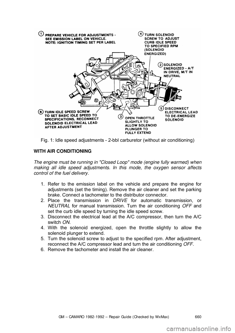
Fig. 1: Idle speed adjustm ents - 2-bbl carburetor (without air conditioning)
WITH AIR CONDITIONING
The engine must be running in "Closed Loop" mode (engine fully warmed) when
making all idle speed adjustments. In this mode, the oxygen sensor affects
control of the fuel delivery.
1. Refer to the emission label on the vehicle and prepare the engine for
adjustments (set the timing). Remove the air cleaner and set the parking
brake. Connect a tachometer to the distributor connector.
2. Place the transmission in DRIVE for automatic transmission, or
NEUTRAL for manual transmission. Tu rn the air conditioning OFF and
set the curb idle speed by turning the idle speed screw.
3. Disconnect the electrical lead at the A/C compressor, then turn the A/C
switch ON.
4. With the solenoid e nergized, open the throttle slightly to allow the
solenoid plunger to extend.
5. Turn the solenoid screw to adjust to the specified rpm. After adjustment,
reconnect the A/C compressor lead and turn the air conditioning OFF.
6. Remove the tachometer and install the air cleaner.
Page 661 of 875

GM – CAMARO 1982-1992 – Repair Guide (Checked by WxMax) 661
Fig. 2: Idle speed adjustm ents - 2-bbl carburetor (with air conditioning)
4-BBL CARBURETOR
WITHOUT AIR CONDITIONING
The engine must be running in "Closed Loop" mode (engine fully warmed) when
making all idle speed adjustments. In this mode, the oxygen sensor affects
control of the fuel delivery.
1. Refer to the emission label on the vehicle and prepare the engine for
adjustments (set the timing). Se t the parking brake. Connect a
tachometer to the dist ributor connector.
2. Place the transmission in DRIVE for automatic transmission, or
NEUTRAL for manual transmission.
3. De-energize the idle speed solenoid by disconnecting the electrical lead.
4. Set the basic idle speed rpm by turning the idle speed screw.
5. Connect a jumper wire from a 12-vo lt power supply to the solenoid.
6. Open the throttle partially to ensure that the solenoid plunger is fully
extended, and allow the throttle lever to close on the plunger.
7. Turn the solenoid plunger to adj ust to the specified rpm. After
adjustment, disconnect the jumper wire and reconnect the solenoid
electrical lead.
8. Remove the tachometer and install the air cleaner.
Page 662 of 875

GM – CAMARO 1982-1992 – Repair Guide (Checked by WxMax) 662
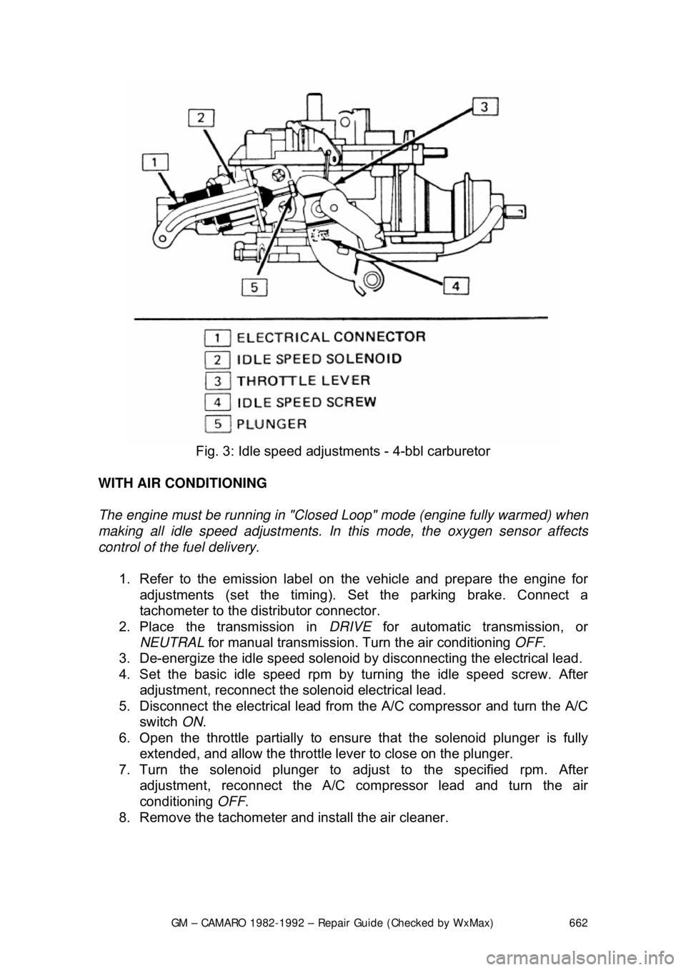
Fig. 3: Idle speed adjustm ents - 4-bbl carburetor
WITH AIR CONDITIONING
The engine must be running in "Closed Loop" mode (engine fully warmed) when
making all idle speed adjustments. In this mode, the oxygen sensor affects
control of the fuel delivery.
1. Refer to the emission label on the vehicle and prepare the engine for
adjustments (set the timing). Se t the parking brake. Connect a
tachometer to the dist ributor connector.
2. Place the transmission in DRIVE for automatic transmission, or
NEUTRAL for manual transmission. Tu rn the air conditioning OFF.
3. De-energize the idle speed solenoid by disconnecting the electrical lead.
4. Set the basic idle speed rpm by turning the idle speed screw. After
adjustment, reconnect the solenoid electrical lead.
5. Disconnect the electrical lead from the A/C compressor and turn the A/C
switch ON.
6. Open the throttle partially to ensure that the solenoid plunger is fully
extended, and allow the throttle lever to close on the plunger.
7. Turn the solenoid plunger to adj ust to the specified rpm. After
adjustment, reconnect the A/C co mpressor lead and turn the air
conditioning OFF.
8. Remove the tachometer and install the air cleaner.
Page 732 of 875

GM – CAMARO 1982-1992 – Repair Guide (Checked by WxMax) 732
MINIMUM IDLE AND THROTTL
E VALVE SYNCHRONIZING
The throttle position of each throttle body must be balanced so that the throttle
plates are synchronized and open si multaneously. These adjustment
procedures must be followed AFTER performing the "Preliminary Adjustments".
1. Remove the air cleaner and plug the vacuum port on the rear TBI unit for
the thermostatic air cleaner.
2. Remove the tamper resistant pl ugs covering both unit throttle stop
screws, if necessary.
3. Block the drive wheels and apply the parking brake.
4. Connect a tachometer to measure rpm.
5. Start the engine and allo w the engine rpm to stabilize at normal operating
temperature.
6. Have a helper apply the brakes and place the transmission in DRIVE.
7. Plug the idle air pass ages of each throttle body with plugs (J-33047 or
equivalent). Make sure the plugs are seated fully in the passage so that
no air leaks exist. The engine rpm should decrease below curb idle
speed. If the engine rpm does not decreas e, check for a vacuum leak.
8. Remove the cap from the ported tube on the rear TBI unit and connect a
vacuum gauge or water manometer.
9. Adjust the rear unit throttle stop screw to obtain approximately
1/2 in. Hg
as read on the vacuum gauge, or 6 in. H
2O as read on the manometer. If
not able to adjust to this level, check that the front unit throttle stop is not
limiting throttle travel.
10. Remove the vacuum gauge or manometer from t he rear unit and install
the cap on the port ed vacuum tube.
11. Remove the cap from the ported va cuum tube on the front TBI unit and
install the gauge or manomet er as before. If the reading is not the same
as the rear unit, proceed as follows: a. Locate the throttle synchronizing screw and collar on the front TBI
unit. The screw may be welded to discourage tampering with this
adjustment. Break the weld, if ne cessary, and install a new screw
with a thread seali ng compound applied.
b. Adjust the screw to obtain approximately
1/2 in. Hg as read on the
vacuum gauge, or 6 in. H
2O on the manometer.
12. Remove the gauge or manometer fr om the ported tube and reinstall the
cap.
13. Adjust the rear throttle stop screw to obtain 475 rpm, with the
transmission in D and the parking brake applied. On manual
transmission models, leave the gear selector in N.
14. Turn the ignition OFF and pl ace automatic transmission in N.
15. Remove idle air passage plugs.
16. Start the engine. It may run at a high rpm but the engine speed should
decrease when the idle air control va lves close the air passages. Stop
the engine when the rpm decreases.
17. The throttle position sensor (TPS) voltage should be checked and adjusted, if necessary.
18. Connect the vacuum line to the TBI unit and install the air cleaner.
19. Reset the idle speed control motors by driving the vehicle to 45 mph.
Page 783 of 875

GM – CAMARO 1982-1992 – Repair Guide (Checked by WxMax) 783
AUTOMATIC TRANSMISSION
FLUID RECOMMENDATIONS
Use only Dexron®II Automati
c Transmission Fluid.
LEVEL CHECK
Fig. 1: Read automatic transmission flui d level on dipstick and add, as required
Check the automatic transmission fluid le vel at each oil change. Driving with too
much or too little transmission fluid ca n damage the transmission. The dipstick
can be found in the rear of the engine compartment. The fluid level should be
checked only when the transmission is at normal operating temperature. If your
Camaro has been driven at highway speeds fo r a long time, in city traffic in hot
weather, or pulling a trailer, wait for about 30 minutes for the fluid to cool down
so a correct reading can be read.
1. Park the car on a level surface, with the parking brake on. Start the
engine and let it idle for about 15 minutes. Move the transmission
through all the gears and then back to P.
2. Remove the dipstick and carefully touch the wet end of the dipstick to see if the fluid is cool, warm, or ho t. Wipe it clean and then reinsert it
firmly. Be sure that it has been pushed all the way in. Remove the
dipstick again and check the fluid leve l while holding it horizontally.
a. If fluid is cool (room temper ature), the level should be about
1/8-3/8
in. (3-10mm) below the ADD mark.