1976 CHEVROLET MONTE CARLO ESP
[x] Cancel search: ESPPage 5 of 102

Downloaded from www.Manualslib.com manuals search engine Front Seat Back ... ~'""\ ..
Front seat backs on two-door
styles are equipped with a self-lock
ing mechanism to
.• keep the seat
back locked in
phlge while in the
up position. The lock release lever
is located on the upper outboard
portion of the
s~at back.
To tilt the
sell,t back forward,
rotate the levertearward and tilt
the seat back
f?rward. When the
seat back
is r¢turned to the up
position,
• the se~t back will auto
matically 'lock.
Keep
belt re~traints.and buckles
clear of mechanism when tilting
folding seats
forward or backwards,
to help prevent damage
to these
belt systems.
Power Operated Front Seats
The six-way power seat control switch
is located
on the driver's seat
left side panel.
The seat can be operated
as
follows:
I. The front control provides up
and down movement of the
frontof the seat.
2. The center control provides
forward and backward move
ment and up and down move
ment of the entire front seat.
3. The provides up
and of the
Power Windows ,
Power windows have an ignition
interlock
so the windows cannot be
operated unless the ignition switch
is in the "on" position.
1-3
REMINDER: Remove the ignition
key when the vehicle
is not at
tended by a responsible person. A
master control for all windows
is
provided at the driver's position,
Individual switches are provided
under each window for passenger
use.
Inside Rearview Mirrors
Switch mirror to night position
to reduce glare from following
headlights. To raise or lower
mir
ror to achieve desired field of.view,
grasp mirror and exert sufficient
pressure by pushing or pulling up,
down or sideways.
Page 14 of 102
Downloaded from www.Manualslib.com manuals search engine Operation Foreign
Countries
.
In
Your car is designed to operate
on unleaded fuel
of approximately
91 reseljl'ch octane number.
If you plan to' operate your car
outs ide . the Continent al limits of
the
U niled States or Canada, there
is .a possibility that the best fuels
available
in some countries are so
low in oclane rating that excessive
knocking and serious engine dam
age may result from their
use. Also,
if leaded fuels are used in vehicles
designed for unleaded fuels, it may result
in the
deactivati on of the
catalytic converter, if the vehicle
is
so equipped , and possibly other
related problems.
The use of leaded
fuel
in a vehicle designed for un
leaded fuel
will require different
maintenance intervals.
To obtain in
formation on the
octan~ rating and
availability of non-leaded fuels
available in the countries in which
you plan to travel , and a mainte
nan ce schedule to
be used when
operating on leaded fuel, write to
Chevrolet Motor Division, Service
Department,Detroit, Michigan
48202, (or in Canada write to
General Motors of Canada Limited,
Owner Relations Department,
Oshawa, Ontario LlJ 5Z6), giving:
1-12
• The vehicle identification num
ber (on plate on instrument
panel ahead of the steering wheel
and vis ible through the wind
shield , or from registration slip
or title)
,.
• The country or countries in which
you plan
to travel.
It is recommended that you not
operate your car in any country not
having fuels meeting the require
ments of your car's engine
as these
may cause engine damage for which
Ch evr olet is not respon sible under
the term s of the Chevrolet New
Vehicle Warranty or Emission
Control Systems Warranty .
Page 17 of 102

Downloaded from www.Manualslib.com manuals search engine f l
Starting the Engine
Automatic TransmISSion
Models
1. Apply the parking brake.
2. Place transmission selector
in uP" or f~Nn (UP" pre
ferred).
A .starter safety switch prevents
starter
operati on while the trans"
mission selector is in any drive
position.
(Iii! is necessary to
re-start the engine with the car .
moving , place the selector lever
in uN".)
3. Depress accelerator pedal and
acti vate starter
as outlined be
low for di1Ierent conditions .
IMPORTANT: ·00 not keep
the starter engaged for more
than
15 seconds at a time. Wait
1 0 or 15 seconds before trying
again.
• Cold Engine ~ Fully depress
. accelerator pedal and slowly
release .
With foot aU the
pedal,
crank the engine by
turning the ignition
key to the
Start
position -release when
engine starts.
If engine starts, bu t fails to
run,
repeat this procedure.
When engine is running
smoothly (approximately 30
seconds), the idle speed may
be reduced by slightly de
pressing the accel erator pedal
and then slowly releasing.
• Warm Engine-Depress ac
celerator pedal about halfway
and hold while cranking the
engine.
2-3
• Extremely Cold Weather
(Below
0 ° F.) (-18° C.) Or
After Car Has Been Stand
ing Idle Several Days
FuUy depress and release ac
celerator pedal two or three
times before cranking ' the
en
gine. With foot aU the .·accel
erator pedal, crank the engine
by turning the key to the
Start
position and relea se when en
gine starts.
Engine Flooded
Depress accelerator pedal and
hold
to floor while starting until en
gine is cleared of excess fuel and is
running smoothly . Never "pump"
the accelerator peda\. .
Warm-Up
Always let the engine idle for 20
to 30 seconds after starting and
drive at moderate speeds for
sev
eral miles, especially during cold
weather .
Page 27 of 102
Downloaded from www.Manualslib.com manuals search engine If the light comes oQ:
• The :parking brake control is not
fully
relea sed or, ,,:
• The service brake system is
partially inoperative .
What to do :
1. Check that the parking brake
is released. If it is ...
2.
Pull off the road and stop, care
fully-remembering that:
'
•
Stoppin g "distances may be
greater. ' '0:
• Greater pMal effort may be
required .: ;
• Pedal
travel may be greater.
3. Try out b~ake operati on by start
ing and
stopping on road shoul
der-then :
• If you judge such operation to
be safe , proceed cautiously at
a safe speed to neare st dealer
for repair.
• Or have car towed to dealer
}or repair .
Continued operation ' of the car in '
this condition
is dangerous.
Headlight High Beam
Indicator Light
The headlights of your ' car have '
high and
low, beams to provi(je you
with proper night-time visibility
for most . driving
conditioQs. The
"low" beams are used during most
city driving. The
"high" beams are
especially useful when
drh;ing on
dark roads since
they provide ex
cellent long range illumination.
The headlight beam
indicator will
be on whenever the high beams or
"brights" are in use. The Headlight
Beam
Switch controls the headlight
beams (see
Page 2-9).
Light Switch
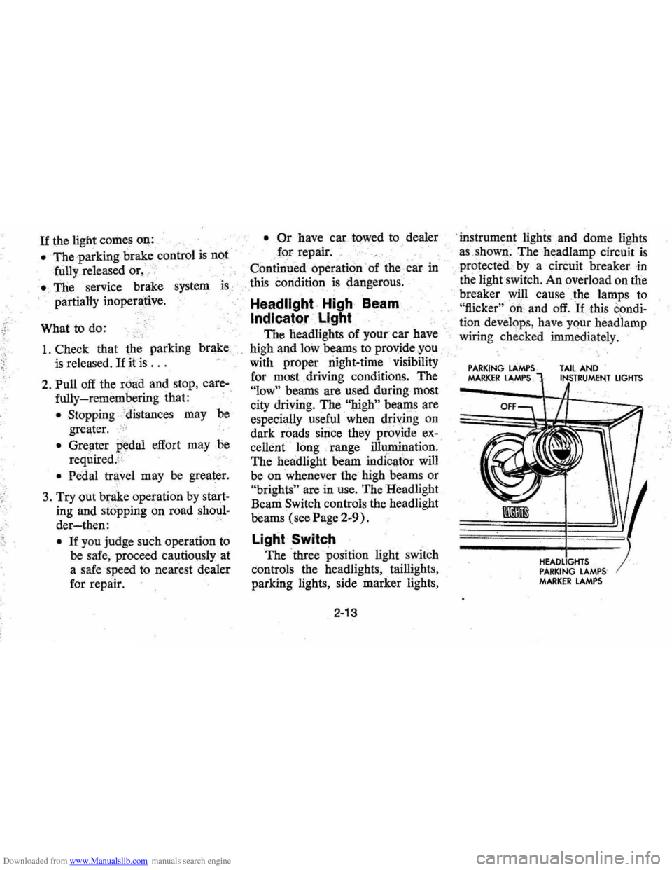
The three position light switch
controls the headlights " taillights,
parking lights, side marker lights,
2-13
'i nstrument lighis and dome lights
a s ,shown . The headlamp circuit
is
protected·· by a circuit breaker in
, tne lightswit ch . An overload on the
breaker will cause the lamps to
"flicker" 00 and off. If this condi
ti on develop s, hav e your headlamp
wiring check ed immedi ately.
PARKING MARKER LAMPS TAIL AND
PARKING LAMPS MARKER LAMPS
LIGHTS
Page 28 of 102
Downloaded from www.Manualslib.com manuals search engine NAL INSTRUMENTS AND 'GAUGES
j:;".,nn,mv Gauge
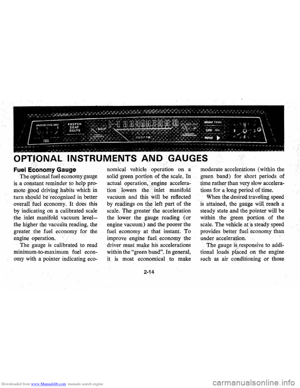
The.optional fuel economy gauge
is a co~stant reminder to help pro
mote ' g~od driving . habits which in
turn should be recognized in better
overalfJuel economy, It does this
by
indicatingon a calibrated scale
the inlet manifold vacuum
level
the higher the vacuum reading, the
greater the fuel economy for the
engine
operation,
The gauge is calibrated to read
minimum -to-maximum fuel
econ
omy with a pointer iudicating eeo-
nomical· vehicle operation on a
solid green portion of the
scale, In
actual operation, )mgiue accelera
tionlowers the " inlet manifold
vacuum and this
will be reflected
by
r~~qings on tbe 'left part of the
scale, The greater" the acceleration
the lower . the gauge
readil1g (or
engine vacuum) and the poorer the
fuel
eeonomyat that instant. To
improve engine fueleconol)lY the
driver must make his accelerations
within
the "green band". In general ,
it
is most economical to make
2-14
moderate accelen'ltions (within the
green band) for short periods of
time rather
thanv«ry slow accelera
tions for along period of time.
When
the desired traveling speed
is attained, the gauge will. reach a
steady state
'.l1-nd the ,pointer will be
within the green portion of the
scale. The vehicle at
'a steady speed
providesbetterfuel.economy than
under acceleration. '
The gauge
is, responsive to addi
tional loads placed on the engine
such
as air conditioning or those
Page 69 of 102
Downloaded from www.Manualslib.com manuals search engine Every two years or 30,000 miles,
whichever occurs first, the cooling
system should be flushed and re
filled using the following recom
mended procedure:
1. Rem()ve radiator cap when en
gineis cool:
• Rotate cap slowly counter
clockwise to detent (Do not
press down while rotating.)
• Wait until residual pressure
(indicated by a hissing
sound) is relieved, then press
down
on cap and continue
to rotate counterclockwise.
2.
Run engine, with radiator cap
removed, until upper radiator
hose
is hot (indicates thermo
stat
is open).
3. Stop engine and open radiator
valve to drain coolant.
(Opera
tion may be speeded by remov
ing drain plugs in the block.)
4. Close valve (install block drain
plugs, if removed) and add
sufficient water to
fill system.
5. Repeat steps
1, 2, 3" and 4, a
sufficient number of times until
the drained liquid
is nearly
colorless.
6. Allow system to drain com
pletely
and then close radiator
drain valve tightly. (Install
block drain plugs, if removed.)
7. Remove recovery cap leaving
hoses in place. Remove coolant
recovery tank, empty fluid,
scrub
and clean bottom and
sides of tank with detergent and
water, flush well with clean
water, drain
and reinstall.
5-8
8. Add sufficient ethylene glycol
coolant, meeting
OM Specifica
tion
1899~M, to provide the re
quired freezing
and corrosion
protection"-at least a 50 per
cent solution
-34°F, -37°C.
Fill radiator to the base of the
radiator filler neck
and bring
level of coolant in the recovery
tank to the
"FULL HOT"
mark. Reinstall recovery tank
cap.
9.
Run engine, with radiator cap
removed, until .radiator upper
hose becomes hot.
I
O. With engine idlil)g, add coolant
to radiator until level reaches
bottom of filler neck; install
cap
making certain arrows line up
with overflow tube.
It is the owner's responsibility to:
• Maintain cooling system freeze
Page 77 of 102
Downloaded from www.Manualslib.com manuals search engine for 3 hours or more, or driven
less than 1 mile.
2. It is normal for tiTe pressures to
increase 4-8 PSI when the tires
become hot from
driving. Do not
"bleed" (reduce tire inflation
pressures)
after driving your
vehicle. Bleeding serves
to in
crease tire flexing and heat build
up which can result in tire dam
age and failure.
3. For sustained driving
at turn
pike speeds; cold inflation
pressures should be increased 4
PSI above the recommended
cold inflation pressures on the
tire placard up
to a maximum of
32
PSI for load range B tires, 36
PSI for load range C, and 40 PSI
for load range D. Sustained
speeds above 75 mph are not
recommended when the 4
PSI
adjustment would require pres
sures greater than the maximum
pressures above.
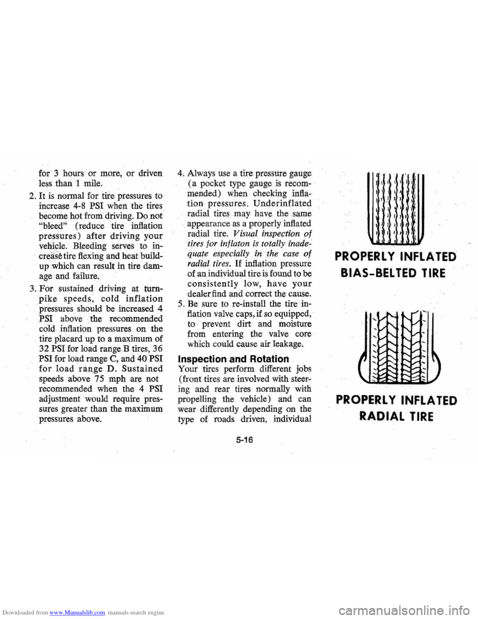
4, Always use a tire pressure gauge
(a pocket type gauge is recom
mended) when checking infla
tion pressures. Underinflated
radial tires may have the same
appearance
as a properly inflated
radial tire.
Visual inspection of
-tires for in/laton is totally inade,
quate especially in the case 0/
radial tires. If inflation pressure
of an individual tire
is found to be
consistently low, have your
dealer find and correct the cause.
5. Be sure to re-install the tire in
flation valve caps, if
so equipped,
to prevent dirt and moisture
from entering the valve core
which could cause air leakage.
Inspection and Rotation
Your tires perform different jobs
(front tires are involved with steer
ing and rear tires normally with
propelling the vehicle) and can
wear differently depending on the
type of roads driven, individual
5-16
I
I '
,
)1, I
I I ( I , I , )' ,t
I ) I )
I , I I I I (
PROPERLY INFLATED
BIAS-BELTED TIRE
PROPERL Y INFLATED
RADIAL TIRE
Page 88 of 102
Downloaded from www.Manualslib.com manuals search engine OWNER
ASSISTANCE
The satisfaction and goodwill of
the owners of Chevrolet products
are of primary concern to your
dealer and the Chevrolet Motor
Division. Normally, any problems
that arise in connection with the
sales transaction or the operation of
your car will be handled by your
dealer's
Sales or Service Depart
ments.
It is recognized, however,
that despite the best intentions of
everyone concerned, misunder
standings will sometimes occur. If
you have a problem that has not
been handled to your satisfaction
through normal channels, we sug
gest that you take the following
steps:
STEP ONE-Discuss your prob
lem
with a member of dealer
ship management. Frequently,
6-4
complaints are the result of a break
down in communications and can
quickly be resolved by a member of
the dealership management.
If the
problem already has been reviewed
with the
Sales Manager or Service
Manager, contact the Dealer him
self
or the General Manager.
STEP TWO-Contact the Chev
rolet Zone
Office closest to you
listed on the following pages
(or
in Canada contact the Gen
eral
Motors Zone Office). When
it appears that your problem
can
not be readily resolved by the deal
ership without additional assist
ance, the matter should be called
to the attention of the Zone's Cus
tomer Services Department and
the following information pro
vided: