1976 CHEVROLET MONTE CARLO clock
[x] Cancel search: clockPage 16 of 102

Downloaded from www.Manualslib.com manuals search engine STEERING COLUMN CdNTROLS
Anti-. Steering
Column Lock
The
anti-th eft lock, located on
the right side of the stee ring col
umn, has five positions:
• Accessory -Permits operation
of electr i
cal accessories when
engine is not running. To
en
gage, push key in and turn
toward you (counterclockwise).
• Lock-Normal parking position.
L
ock s igniti on and provides added
theft protection
by prevent
ing normal operation of steering
wheel and shift controls . to
"lock"
po sition and removed until trans
mission is placed in "park".
• Off
-Permits turning engine off
without locking steering wheel and
shift controls.
• Run (ON) -Normal operating
position
. .
•
Start -Permits engagement of
starter.
NOTE: The ontl-theft otee,lng column lock is not 8:,lubltItUte tor· the parking brake. Always let the , parking brak, when leaving the car una"ended.
If difficulty is experienced in
turning the ignition key and lock
knob to unlock the ignition,
at
tempt to turn the steering wheel lIS
hard as possible in the direction the
wheels are turned.
At the same
time turn the ignition-lock knob in
2-2
a clockwise direction wi(h as.much
effort
as you can apply with your
own hand. Do not attempt to
use
a tool of any kind to apply addi
tional force on the lock knob, as
this could break the knob.
Parking
When leaving your car unattended:
• Set parking brake.
• Place automatic transmission se
lector in Park.
•
Turnkey to LOCK position.
• Remove key (the buzzer will re
mind you).
• Lock all doors.
IMPORTANT : Do not park your car over combustible materials, such 8S grlss or leaves, which can come Inlo contact with the hot exhaust system and cause such materials to Ignite under certain wind and weather condition ••
NOTICE:
Do not I.ave your car unattended with ~ engine running. If the engine
should overheat While your car is -unat·
tended , the temperature warning light or gauge would go unheed9d, which could result in extensive damage to your car.
Page 24 of 102
Downloaded from www.Manualslib.com manuals search engine INSTRUMENT PANEL AND CONTROLS
o STANDARD
o OPTIONAL
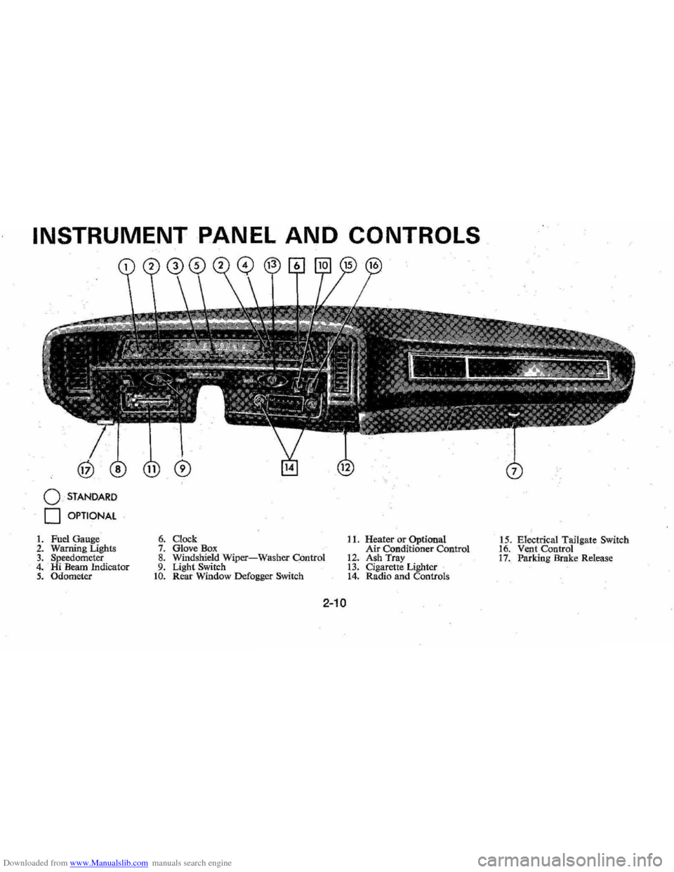
1. Fuel Gauge 2. Warning Lighls 3. Speedometer 4. Hi Beam Indicator 5. Odometer
6. Clock 7. Glove Box 8. Windshield Wiper-Washer COntrol 9. Light Switch to. Rear Window Defogger Switch
11. Heater or Optional
Air Conditioner Control
12. Ash Tray 13. Cigarette Lighter 14. Radio and Controls 1
5 . Electrical Tailgate Switch
16. Vent Control 17. Paridng Brake Release
2-10
Page 29 of 102
Downloaded from www.Manualslib.com manuals search engine I0'ads imp0'sed by .. trlliler hauling.
Cempensatef0'r thes~ l0'wer gauge
readings
resulting frem these heaVy
'Ib ads t0' produce gO'?d fuel ec0'n
emy.
. <,
Engine Temper~'iure. Gauge
This 0'Pti0'n~r',,'gauge indicates
c0'0'lant temperaplre which will
yary with air
teqiperature and 0'P
erating c0'nditi{>,iiS. The ignitien
switch must
be;" 0'n f0'r accurate
,re
the P0'inter to'iim0'vebey0'nd tije
center 0'f the ljimd. Should P0'inter
m0've t0' the line at the "H" end of
the band , stop engine 0'r reduce ,
speed
t0' penllit engine t0' cool.
Headlamp "ON"
Warning Buzzer
The eptienal headlamp reminder
buzzer provides
an audible warn
ing that the main light switch is in
one 0'f the "0'n"P0'siti0'ns ; either
pMking lights Of headlights.
The reminder ,buzzer is actuated
0'nly whenthe igniti0'n switch is
turned
i0' '''OFF'' er "LOCK" posi
ti0'n,
Clock
Reset th~ cl0'ck,if yeur car is S0'
'equipped, by pulling eut the kn0'b
.
and turning the hands cl0'ck\\fise if
slew , c0'unterclockwise if fast. This
will, if the
cl0'ck errer is five min
utes er. m0're,~utematicallyc0'm
pen sate f0'r tim.e' gain 0'r l~g, Sev
eral resettings, sev.eral daysi',apart,
maybe needed te pr0'perl y adjust
the
clOCk mechanism . Have yeur
c
l0'ck cleaned and 'eiled by a cem"
petent .cl0'ck serviceman "at least
every
twe years,
Cigarette Lighter
The cigarette lighter. is I0'cated
en the instrument panel face, T0'
,2-15
operate, push it in, When it be
C0'm.es heated, it aut0'matically P0'PS
eut ready fo r use,
WindshiEild Wiper and
Washer
The windshield wiping system
op(;lratesat tW0' speed s and is de
.
signed t0'wipe clear specific areas
of the windshield under m0'st in
, Clement "''leath
er cenditiens, The
windshielrlwipers w0'rk electri
cally and are not affected ' by en
gineeperatien,
FIlsh . the centrel levetDewn te
start the electric windshie ld wiper,
The
tW0'-speed electric wiper has
botli a' "lew " and a "high" speed
pesitien,
Pressing the centrel will send a
measured
ameunt ef water 0'r ether
cleaning agent ent0' the windshield,
Fill the washer
jar only % full
during the winter
te allew fer eX
pansien if the temperature sh0'uld
Page 46 of 102
Downloaded from www.Manualslib.com manuals search engine ond seat forward for access to
the third seat area.
2. Lift third seat back hinged filler
panel
rearward onto seat back,
then, grasp seat back handle and
lift seat
back. upward until it
locks
in the full "up" position
(see illustration
0).
Keep belt restraints and buckles
clear of mechanism when folding
seats,to prevent damage to these
belt
systems. C·>·i
Retractable Tail Gate
The retractable tail gate is de
signed to
lower into the underbody
and in general follows the body
contour during the opening and
closing cycles. Similarly, the back
window, which
is separate of the
gate, raises upward and into the
space between the roof inner and
outer panels.
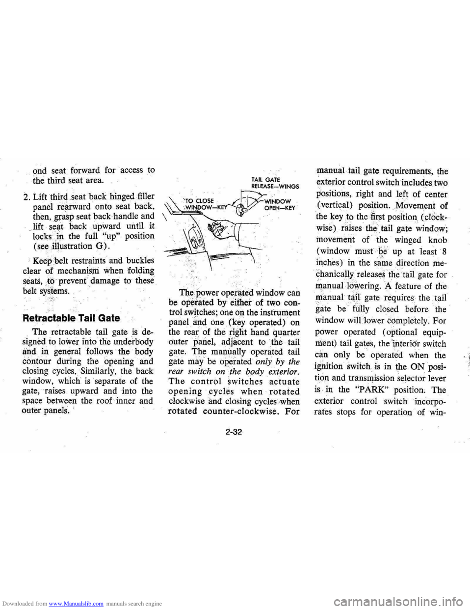
TAIL GATE RELEASE~WINGS
'TO CLOSE --C~WINDOW ~ WINDOW-KEY ~:/ OPEN-KEY
The power operl)ted window can
be
op~rated by either of two con
trol switches; one on the instrument
panel
~nd one (key operated) on
the
rea~ of the tight hand quarter
outer
panel, adjacent to the tail
gate. The manually operated tail
gate
may" be operated only by the
rear switch on the body exterior.
The control switches actuate
openingcycle.s when rotated
clockwise and closing cycles when
rotated counter-clockwise. For
2-32
manual tail gate requirements, the
exterior control switch includes two
positions, right and left of center
(vertical) position. Movement of
the
key to the first position (cl()ck
wise) raises the
tail gate window;
movement of the winged knob
(window must
Be up at least 8
iqches) in the same direction me
chanical!>: releases the tail gate for
manual16wering. A feature of the
~anual tap gate requires the tail
gate be
fUlly closed before the
window
will lower completely. For
power operated (optional equip
ment) tail gates, thei,nterior switch
can only be operated when the
ignition switch
is in the ON posi
tion and transll)ission selector lever
is in the "PARK" position. The
exterior control switch incorpo
rates stops for operation of win-
< I
Page 52 of 102
Downloaded from www.Manualslib.com manuals search engine equipped) by reaching under the
cover (forward
of. center) and
unhooking :and pulling down on
the
locking rod loeated on the
bottom inside edge of the cover
flange. Tip cover outward at the
top while raising up and away
from the mounting hooks.
3 . Remove hub cap or wheel cover
with flat end
of wheel nut
wrench and loosen , but do not
remove
nutS, by turning coun
terclockwise.
COUPE AND S£DAH MODElS
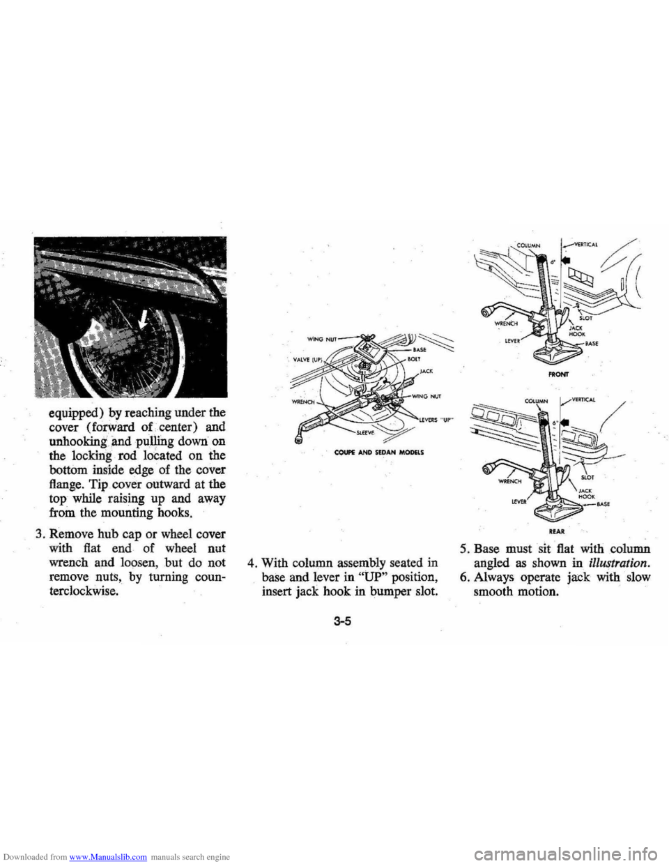
4 . With column assembly seated in
base and lever in
"UP" position,
insert jack hook in bumper slot.
3-5
PltONT
ItfA"
5. Base must sit flat with column
angled
as shown in illustration.
6. Always operate jack with slow
smooth motion.
Page 63 of 102
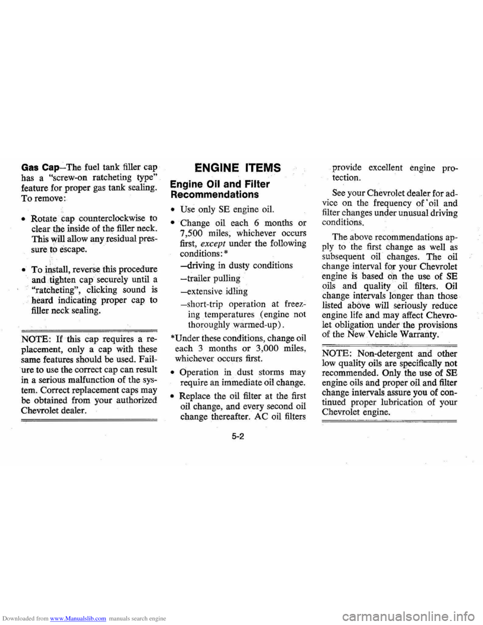
Downloaded from www.Manualslib.com manuals search engine Gas Cap-The fuel tank filler cap
has a
"Screw-on ratcheting type"
feature for proper gas tank sealing.
To remove:
• Rotate ~ap counterclockwise to
clear
the inside of the filler neck.
This will allow any residual
pres
sure t!J escape.
• To iQstall, reverse this procedure
and . tighten cap securely until a
"ratcheting", . clicking sound is
heard indicating proper cap to
filler neck sealing.
NOTE: If this cap requires a re
placement , only a cap with these
same features should
be used. Fail
ure to use the correct cap can result
in a serious malfunction of the
sys
tem. Correct replacement caps may
be obtained from your authorized
Chevrolet dealer.
ENGINE ITEMS
Engine Oil and Filter
Recommendations
• Use only SE engine oil.
• Change oil each 6 months or
7,500 miles, whichever occurs
first ,
except under the following
conditions:
•
-driving in dusty conditions
-trailer pulling '
-extensive idling
-short-trip operation at freez-
ing
ternperatures( engine not
thoroughly warmed-up).
'Under these conditions, change oil
each 3 month s
or 3,000 miles,
whichever occurs first.
• Operation in dust stOmlS may
require an immediate oil change.
• Replace the oil filter at the first
oil change, and every second oil
change thereafter. AC oil filters
5-2
provide excellent engine pro
tection.
See your Chevrolet dealer for ad
vice on the frequency of' oil and
filter changes under unusual driving
conditions.
The above recommendations
ap
ply to the first change as well as
subsequent oil changes. The oil
change interval for your Chevrolet
engine
is based on the use of SE
oils and quality oil filters. Oil
change intervals longer than those
listed
above will seriously reduce
engine life and may affect
Chevro
let obligation undetthe provisions
of the New Vehicle Warranty.
NOTE: Non-detergent and other
low quality oils are
sgecifically not
recommended .
Only the use of SE
engine oils and proper oil and filter
change intervals assure you of
con
tinued proper lubrication of your
Chevrolet engine.
Page 69 of 102
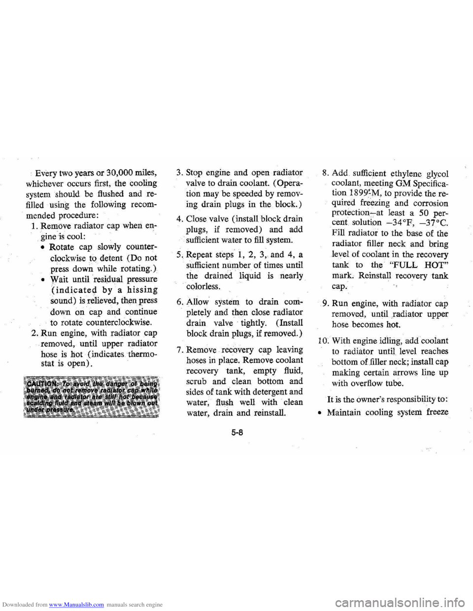
Downloaded from www.Manualslib.com manuals search engine Every two years or 30,000 miles,
whichever occurs first, the cooling
system should be flushed and re
filled using the following recom
mended procedure:
1. Rem()ve radiator cap when en
gineis cool:
• Rotate cap slowly counter
clockwise to detent (Do not
press down while rotating.)
• Wait until residual pressure
(indicated by a hissing
sound) is relieved, then press
down
on cap and continue
to rotate counterclockwise.
2.
Run engine, with radiator cap
removed, until upper radiator
hose
is hot (indicates thermo
stat
is open).
3. Stop engine and open radiator
valve to drain coolant.
(Opera
tion may be speeded by remov
ing drain plugs in the block.)
4. Close valve (install block drain
plugs, if removed) and add
sufficient water to
fill system.
5. Repeat steps
1, 2, 3" and 4, a
sufficient number of times until
the drained liquid
is nearly
colorless.
6. Allow system to drain com
pletely
and then close radiator
drain valve tightly. (Install
block drain plugs, if removed.)
7. Remove recovery cap leaving
hoses in place. Remove coolant
recovery tank, empty fluid,
scrub
and clean bottom and
sides of tank with detergent and
water, flush well with clean
water, drain
and reinstall.
5-8
8. Add sufficient ethylene glycol
coolant, meeting
OM Specifica
tion
1899~M, to provide the re
quired freezing
and corrosion
protection"-at least a 50 per
cent solution
-34°F, -37°C.
Fill radiator to the base of the
radiator filler neck
and bring
level of coolant in the recovery
tank to the
"FULL HOT"
mark. Reinstall recovery tank
cap.
9.
Run engine, with radiator cap
removed, until .radiator upper
hose becomes hot.
I
O. With engine idlil)g, add coolant
to radiator until level reaches
bottom of filler neck; install
cap
making certain arrows line up
with overflow tube.
It is the owner's responsibility to:
• Maintain cooling system freeze
Page 87 of 102
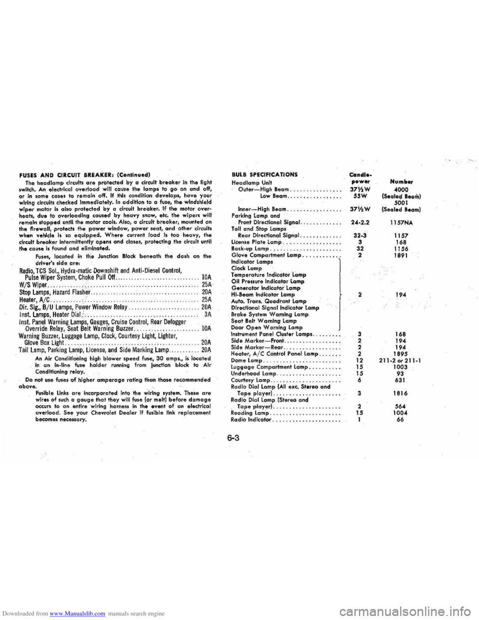
Downloaded from www.Manualslib.com manuals search engine FUSES AND CIRCUIT BREAKER: (Continued) Tho hSDdlomp clrculls are proleded by a dreult breaker In the light Iwitch. An slsc:trlcol overload will cause the lamps to go on and off, or In som~ cOles to remain off'. If this condition deve lo ps, have your
wiring circuit. checked Immediately. In addition to a fuse, the windshield
wiper mot or Is also protected by a circuit breaker. If the motor oyer· heats, due to overk>adlng caused by heClvy snow, etc. tl\e wipers will
remam stopped unltl the motor cools. Also, a c.Irc:uit brea ker. mounted on
the firewall, protects the power window, power seat, and other circuits when vehicle Is so equipp.d. Where current load Is too heavy, the
circuit breake r Intermittently opens and closes, protecting the circuit until the cause Is found and eliminated. Fuses, located in the Junction Block beneath the dash on the driver's .Ide are: Radio, TCS SoL, Hydra·matic Downshift and Anti·Diesel Control, Pulse Wiper System, ChQke Pull Off ........................ . W/S Wiper............. .• . .. . .................... . Stop Lamps, Hazard flasher..... . ......... . Heater, A /C ...... . . .. ' Dir. Sig., B /U lamps, Power Window Relay. Inst.lamps, Heater Dial,::, ..... Inst. Panel Warning Lamps, Gauges, Cruise Control, Rear Defogger Override Relay, SeaL8elt Warning Buzzer. ..... -. c •••••. Warning Buuer, Luggage Lamp, Clock, Courtesy Light, Ligflter,
lOA 25A lOA 25A .. 20A 3 A
lOA
Glove Box Light. . . . .. . . . . . . . ..... 20A Tail lamp, Parking Lamp, License, and Side Marking Lamp... . ..... 20A
An Air Conditioning high blower speed fuse, 30 amps., is located in an In-tine fuse holder runnin g from JUnction block to AI ... Conditioning -relay. Do not Ufe fuses of higher amperage rating than those recommended
obove. Fusible ,
LInks are in(:orporated into 'he wiring system. These are wires of such a gauge that they will fuse (or melt) before damage occun to an _ent ire wiring harn ess in tile even' of an electrical
overload. See your Chevrole t Deal er if fusible link re placement
becom es necessary.
BULB SPECIFICATIONS Heodlamp Unit Outer-High Beam ..........•..•.. Low 8eam .... · .•.••..••....
Inner -High Beam .......... , . •.. .. Parking lamp and Front Directional Signal. .......••... Toil and Stop Lamps Re,ar Directianal Slgn(ll .......•..... license Plate Lamp ............•..... Back.up Lamp ................•.••.. Glo .... Comportment lamp .•..••.....• Indicotor lamps Clock lamp Temperature Indicdtor Lamp 011 Pressure Indica'tor lamp Generator Indicator lamp Hi-880m Indkator lamp Auto. Trans. Quadrant Lamp
Directional Signal Indicator Lamp
Brake System W,a ,rn!ng Lamp Seat Belt Warning Lamp oOor Open Warning Lamp Inshvmen' Panel Ou.ter lamps. Sid. Morker-FrOl1i ................. . Side Marker-Rear ................. . Heater, Ale COntrol Panel Lamp .....•.
D ome Lamp ....................... . lU9t1oge Compartment Lamp ......... . Underhood lamp ................... . Courtesy Lamp ..................... .
Radio Dial Lamp (All exe. Stereo ond Tape player) . . ................ . RadiO, Oial Lamp (Stereo and Tape player) .................... .
Reading lamp ..................•... Radio Indicator .......••..••.•.••...
6-3
Can_uea power Humb ...
37Y~W 4000 55W (S.ale~, Beom)
37V1W 5001 (Sealed Beam)
24-2.2 11S7NA
32-3 1157 3 168
32 I J 56 2 1891
2 194
3 168
2 194
2
194
2 1895
12 211·2or211al 15 1003 15 93
6 631
3 1816
2 564 15 1004 I 66