1974 FORD CAPRI check oil
[x] Cancel search: check oilPage 126 of 205

Chapter 6 Manual gearbox and automatic transmission 125
18 Carefully ~ove the lrilnsmission reilrwards ilnd downwmds, and
away from the car. Make sur e that lhe torque conver ter rema ins fully in
the transmission. 19 Refilling is the reverse of remova l but ensure that the torque converter drain plug is In line wIth the hole in the driveplate . To check
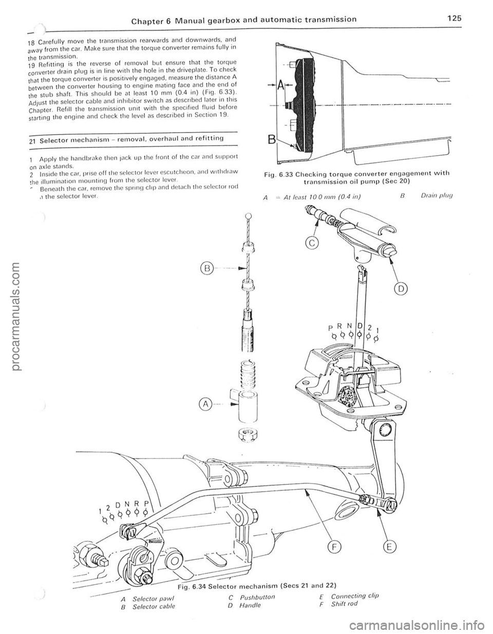
that the torque converter is positively engaged. measure the distance A between the converter housing to engine mJting fJce and the end of the $llIb ShilfL This should be al leilsl 10 mm (0.4 in) (Fig. 633). Adjust the selector cilble i1nd inhlbilOr switch i1S deSCribed later ill this Chapter. Reftll the 1riln smission unit with lhe specified flu,d before StDrlll1g the ennine i1nd check lhe level i1S describe(f in Section 19.
21 Selecto r mechililism -removnl. overhnlll ilud refitting
Apply the hnndbr,lke then Inek up the front of the car ilntl suppo'1
on ilxle stands. 2 Insi(fe the cm. prose off th e selector lever escutcheon. ,md wothrhaw
!he Illumillnt,on 1ll0U1l1l1l\J from the selec tor lever Oeneilth the CM. remove the Spr
r(
®---i
A
6 .33 Checking torque converter engagement with trnnsmission oil pump (Sec 20)
Alle,1S1 100111111 (0.4 ill) 8 O(.1ill (lluy
:-----
--
6 .34 Selector mechanism (Secs 2 1 and 22)
A SclcclOf pawl B SClccrof cabie
C Pusllbu/loll
o Natld/c
f Connccting clip F Shill (od
.'
. 1 , ;
I
procarmanuals.com
Page 134 of 205

1 Chapter 8 Rear axle 133
Fig. 8 .1 CrOSS-Sl!ction o f cnrlv rCilr ;1xlo (Sec 1)
A Fixed /ellglh SIJ.1C(!f B Pinion slum
2 Routino mnintcnoncc
C Dd1clCII1.11 S/II"'$
At lhe uHerv"ls specIfIed 111 the HOlltmc M.111l1cn;mc c SCCllon III the 110111 0 1 the mnnu;1I c""y oul the following p,uccdw(!.
Check fcar axle oil level 1 Jilek lIlllhc IvaI of the Cil! ;uHf suPPOtl on axle ~I"nds T o C!lSI'''') li1,'l Ihe Cilr is lellel ;,150 I
3 R e
posi tioned lIancnlh the sid(Hllemhe.s . Cho ck thc tronl wheels and rcmove the .ear wheelS . 2 Mark thc p.ol>elle. sh;J1! ilnd .eil'
t'ansverse ,od from the .ea. (Ide wl,h refalCnce 10 Chal >!el 9
5 CI
COUAPS'8ll -----i--i!~e"'.!i SPACH'
,
Fig. 6 .2 Cross·sc ction of I"ter rear Ilxle (See 1)
Fig. 6.3 Removing the rear ax le fillo r 1)lug (Sec 2)
Fig. 8.4 Flexible brake hose connection to the .ear axlearrowed (Sec 3 )
procarmanuals.com
Page 135 of 205

1
134 Chapte r 8 Rea r axl e
FiO. 8.5 Discorlllccti!l9 the rcar sI"biliser Iwr (Sec 3)
7 U~"'!I u"ps (FlU 8 5) I)UU rile s1.1h,l,s(lI b.ll 10 lilt:! lCol. while unstocwIIlIJ the mOlllllnlU I)oIIS from the Ie;)' ;l~II!. flcl110vc the C!JIllI'S 8 W,lh the rC:II Ildc sUlt,lbly SUIlI>o.ICd. lIIlSCICW rhe nulS hom the hallom 01 the U-bolts i1rld reOlOlle rhe lowel S I)llrlU p l;lrcs .. ",t! 1115 .. 1<11015. 9 Wllh rhe help of an asslSlilnt. hft the rem a~lc over the "~
Chock Ihe front wheels then jack up the re,lr of the c~r ilnd support with onle stilnds. Remove the .ear wheel 2 Ilelea se the hilndb.nke and .emove Ihe brake drum.
3 USIng a socket through the special holes in the drive lI.::tnge. unsc'ew the bollS secu.ing the b.::tckp late and bearing ,el.::tinor to tho a~le cilSln g (pholo). 11 Withdraw tho a~leshnft. together with the bearing. " it is tight due 10 tho oulor Ir
ig. 8
.6 RelHoving t h o Mdeshalt .e l'l ining hoits (Soc 4)
If
I
/1
II
I
\,
Fig 8 .7 U sing long bolls to ""ithdra"" tho a~leshaft (Sec 4)
cd
procarmanuals.com
Page 136 of 205

m
)
Chapter 8 Rear axle 135
Fig 8 .8 Drilling the beMing rf!t
5 AxlcshiJft homing -renewal
Noto: A SfJL'CI.1f 1001 IS "Hlliller! /0 n'III1:''''''[1 (,0111 lilt' axles/mIl (s,:c Fly 89) 1 Remove the ;,xlushalt as ,h:sG"hcd 1(' St;CIl0n 1 2 Usin\J all 8 mill (0.31 In) dldl, 1Il;,kc a hole III the he,Hlnt! ,etauun\1 119 . t
G Cleiln the l1xlcshnf1. be,non\) ,,,t;WlC' ,Hld "xle C.,1511l\) 7 Locl1le the loe1ll1ll9 HIWlIlel 011 the l1xleshl1lt. followed uy tho new uoa,ing wIth the 001 sel1l [l1CIll\) l1WilY ['om the l1~leshaft Hallge. 8 Slide on the new hea'lIl\) rcta"lIn\) '1119 and pr ess J fully 11\l111l1st tile hearing inner IWck. uSIng a slJItJIJle puller or J ICWlth oftuue. 9 Re fIt Ihe l1xleshalt wllh refe'ence to S ectIon <1
6 Axle reM cover relllov,,1 ilnd refitting
Chock the hont wheels then lilck up the re,l( o f the Cl1r il'l(l SOPPOI1 on axle stands.
2 Cl em1 the reM cover .Jnd surroundIng .Jre" (photo) 3 Remove the hllmlbr"ke relay le ver lind seco nd.Jry cable. or
transverse ,od (as ;;Jpplicilblc) with reletCnce to Ch"pter 9. <1 Place a suitable container helle~th the reM "x Ie to c~tch the oil as the rear cover is removed.
5 Undo and remove t he ten IJOlt s and sprinU washers lhilt securo the reill cover to the llIl,l l drive housillg LIlt aWilY th e re"r cover and its
\Jasko!. ~ Before refitting the ,oar cover Illilke sure thm the mating fJces ilre free of th() old Uaskct or 10nlting compound.
7 FIt a new uasket Jnd then the lea, cover and secure wIth the ten bolts and spring washers. The cover bolts protrude IntO the fillal drive hOUSor1U so it is important that a SUlwble oll·resist.Jr1t scaling
... __ ro*
Fig. 8.9 Usill(J the special Ford tool to removc the axlesllilfl henring (Sec 5)
r;olllpoulid IS SlIll:ilr() d onto lioe Ihro,'ds of each boll bef ore it IS [,twd. 8 TIUhwll tllr: cover secu,,"!.! holls 10 lhe spec,[,ed torque Wfl:IICh
se ttln\)
9 ReCOlillect
Iht! h,lndbr,l~e components with re ference to ChJp ter 9. 10 R efil l ti,e 1e;1I ,ule with the correct 9rJde 01 oil then lower the C,lr to
the UIOUIl(i
G
2 Axle reM cover
7
Pinion oil seal -re"cw,,1
This ope r,ltion may be performed WIth the rear axle in position or on
the benc h
2 Undo ~nd remove the two holts. sprinU Jlld plain washers that secure lhe centre bearing support to the under51(fe of the body (reler to
Chapter 7) 3 With a sc"ber 0' fde. Ill
propeller sha h to ttt() flool I I
J m
procarmanuals.com
Page 137 of 205

Chapter 8 Rear axle 136 )
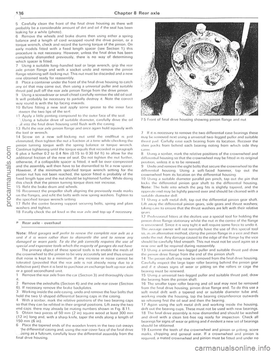
5 C~rellJlly cle~n Ihe Ir Oll 1 01 the Im,ll d"ve housinU ~s there will Ilroll
P ReM axle -o verh;;lul
Note: Mosl ymilycs wtlf Ilft'h" 10 If.'IWW Iflt' comfllelC IC,ll ,Jxfc ,15 .1 111111 d II IS WOII! ,.II/IC' I/Ioll! 10 rf,SllliI",fc Ille UII/I 10 lel/t·w '''IV r/;/11I.Jycd 01 WOIII poll Is ro do tlw ,ob correclly Icquires Ifle usc 01 spccial <111(1 cxpellsive loofs willch tin' "'",u/lly of y"WY"'S do 1/01 h,lVl' The P"n1
,' . 2 Remove the a xlesh;;lhs (Sec lIon 4) "nd the;lxle ,e". covel (Secllon 6) . If rleceSS;;Jry remove lire !H" ke !liIckpl;,ws 3 WOlk,n!) inside IIlI! axle casUlU . undo .lnd .emove Ihe four bolts th" t hold Ihe IWO U'Shill>cd dlllerentl,ll be"rmg CilPS III the Cilsing. 4 W,lh a sc.iber. m
15 Froni I'll Im
",.IY I,,, ",move(1 Ih:xl uSlnU " ulllvers,,1 two·leuged puliCI and sui!
NOLI! : 1 hu h"le 11110 willch thc peu Irts IS shghlly "'I>c.ed. lind the I>pl''''.'I'! "",1 may he IrIJhLly peelH)d over ;'Iml should he r.:!e;rned with a ·.u,I.II,I" ,".11111;1". ,tr,ll 11 th'''!1 a ... "It IIlI;t.11 dllfl. "'i> out Ihe drllelenli"l p"uon Ue", slr"h. 1.011 .Iw.ly tlr" d,lh;u!Oltl;r1 pinian ue,us. sido {leMS "lid IhruSI was hers; IA"'!l':,"" 10 ell::ure Ih"t the th,usl washe.s ",e lell wllh Ihe ir relative
liP,"" 12 1'",1"~"If)f .. ,1 Il1te.s (It Ihe
procarmanuals.com
Page 139 of 205

. )
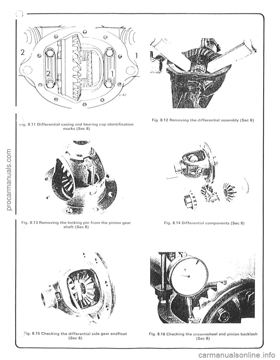
r'9' 8.11 Differential ClOsing and bCiHillU C
•
' • .'.....
• • I , , ,
I , , '<' • . ,
~( I
' ...... ,
~i9. 8.1 5 Checking tho d iff erential sid e gear ontilioal (Sec 8)
Fig. 8.12 RClll ovin!J the differential assemhlv (Sec 8)
'.
}
fig . 8 .1 4 Oiffercntiill cOIllI)oncnlS (Sec 8)
Fig. 8.1 6 Chocking the crownwheel and pinion backlash (Sec 8)
1
procarmanuals.com
Page 140 of 205

•
Chapter 8 Rear axle 139
ci,cumS«"Ulces mny only one pmt of the two be renewed. fnspect the dllfe,enti,ll pinions nnd side gems for signs of pitting. score mMks. Chipping nnd general wem. Obtain new gears as necessa,y . Inspect the th,ust washers lor signs of weM or deep sco,ing. Obwin new thrust wnshe,s as necessary. Once the pinion o il senl has been disturbed it must be discMded and a new one obtained. 20 When new pnrts have been obwined ns required. reassembly cnn begin. First lit the thrust washers to the side gems and place them in position in the differential housing. The ground side of the thrust washers IllUSt lace the side gC.Jrs. 21 Place tile thrust wilshers behind the dillelentini pinion genrs i1nd mesh these twO Oems with the Side gears through the tWI) ilpertores in the lilllerentlill housing. Milke sure they ilre diametlicilily opposite 10 each other. RO«l!e the clillerent'i11 pinion gears through 90' so brinUlI1\j them into line with the pinion genr shnlt bore 111 the housinlt 22 Insert the pinion genr shnft with the lock In!) p'n hole III line with the pill hole. 23 Usinu leeler 1),IU!Jcs. measure the en{lll(",t 01 ench s,de Be,,,. II the speclficd h\Jure IS excecrt"d. IU!W tl"u~t washlllS mu"t he olJt,uned
-omnlllie the a~~el)lhly ,lg,llll ,trld ht new thll,st wa:,lu'
28 Using soitable diameter tubes. fit the two Wper roller bearing cones into the finnl dlive housing. making sure that they ale litted the correct way round. 29 Slide the shim and spncer onlO the pinion shalt and insert inlo t he final drive housing. 30 Relit the second and smaller diameter wper loller bea,ino onto the end of the pinion shaft lind 101i0w Ihis Wilh a new oil seal. Sefore Ihe senl is nctually fitted. apply some grense to the inner Ince between the two lips of the seal. 31 Apply n little jOinting compoond to the outer Ince of the seD I. 32 Using n tuhulilr dllft 01 suitable dinmeter, carefully drive the oil seal into the fillal (hive housinlJ. Make quite sore thnt it is lilted squarely and flush with the housinU. 33 Refn the drive pinion IInnge nnd hold securely in n bench vice. It II fixed lenIJth spncCl is Itlted. fit ilnd tighten the pinion nut 10 the spec ,lied lorque. If a collapsihle spnce r is f,tte d. follow the prOCedlHe
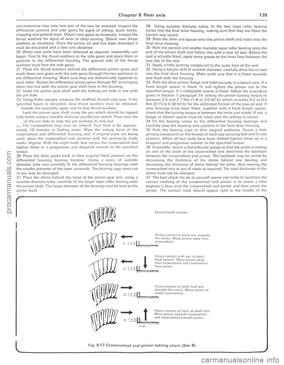
g iven in Section 7 paragraph 14. setting the pinion turning to'que to hetween 25 nnd 2.7 Nnt (1.810 2 0 Ihf It) which includes 0.2 to 0.<1 Nm (0.15 10 0.30 Ibl It) lor the ndriitional friction of the new oil senl II new hea,inns h~ve heen filted. logether With n li~e(l len(Jth SP,lCer. check thm the tOrlllllg torque is bel ween the limits just stmed. If not. a longer or shorter spilcer must he I,tted until the setting IS correct 34 Fit the healing cones to the cf,fierenllal houslIlg heallll(Js and carefully ease the housing Into posilion in the finill drive housmg 35 Relit the be,IIII'!J CilpS in thell originnl pOSitions. Srnc,ll n httle JOlntmg compound on the threilcfs 01 each cnp secuIII'O bolt nnd fit 11110 position. When ,111 low halts have bcen rein ted tiUhten these up in a (h"IJonal and progresSive milnne, to the speCi fied torque. 36 I I pOSSIble. 1Il00nt n dlnl in(licntor onu(Je so thnt the probe IS resting on one of the teeth of the crownwheel and determine the backlash hetween the clownwheel and pillion. The bileklash may be vMicd by elecreasll'\) the thickness of the shims bellind one beilling nnd incrensing the thickness of shirns behind the othcr. thus moving the crownwheel ;nlO or out ofmcsh as requi,ed. The tOt.llthlckness 01 the shims must not be chnn\)ed. 37 The hesl check the do·it·yourself owner cnn make to aSCerta", the correct meshinu of the crownwheel ilnd pinion is to smear ,I htt le engineer's blue onto the crownwheel and pinion iJnd then lot"te the pinion. The con1
_
t Heavy conWCl 0" huel. at 100lh !,leu Move p'",on lowa,ds crownwhcd u:.!:.crt:1 3nd c,ownwhuel towards p,n,on
.~\;!~" •. ,;.';,;,"",.,=,"--
l ' Fig. 8.17 CrownwheeJ and pinion setting chart (Sec 8)
, ,
, ,
"
procarmanuals.com
Page 144 of 205

) Chapter 9 Braking syste m 143
2
Fig. 9.1 DU
2 ROlltine maintenance
Al III<, u,h!lvals speClficed in the Routine M
2.4 ;-.-
uejJ.es~ the rubue' membrJne to check the fluid low level
Warning IrUht
3 To top up the fluid unscrew the fill er cap whrle holding the c,lhle connector sWtionar y. and add brake lIuid ns necessJr y. R efit the cnp on completion. 4 When checking the brnk e fluid level it is n good practice to also check the low level wnrning light With the hnndbwke rele
Re leuse the hilndb'
Fig. 9.2 Handbr a ke lin k ag e lubrication points (arro\Ncd) on early models (Sec 2)
I .
i
! j..
1:
, ,
procarmanuals.com