1974 FORD CAPRI light
[x] Cancel search: lightPage 94 of 205
Chapter 4 Ignition system 93
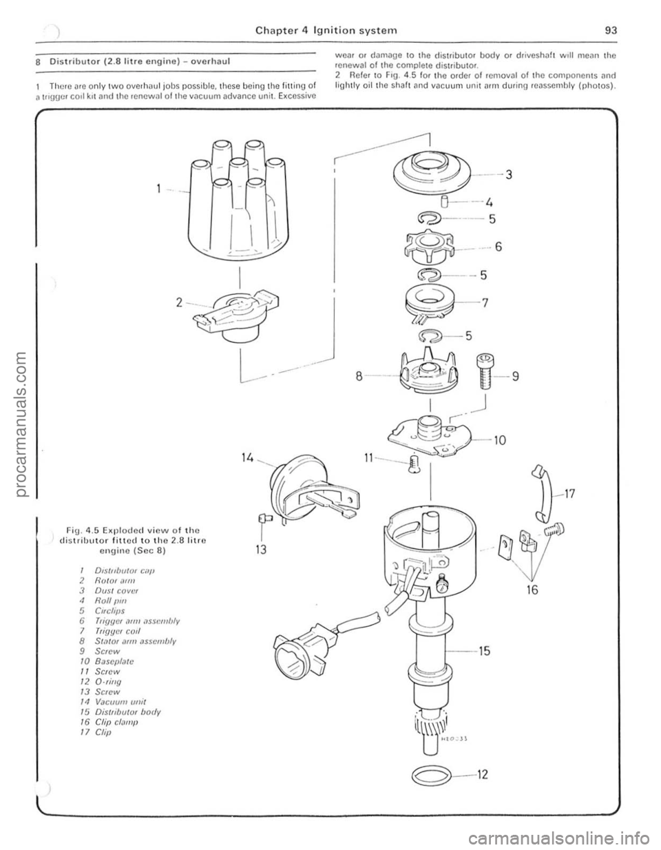
8 Distributor (2.8 lilre engine) -overhaul
There arc only two overh"ul jol)s possible. these being the fitling of a t"UUcr carl krtllnd the renewal of the vacuum advance uni\. Excessive
I -
Fig. 4.5 Exploded view 01 the distrihutor fitted to the 2.6 litru cnginc (Scc 6) 13
, DIS/111m/or Cill' 2 HOIQ'lIrm 3 Du,~1 covtJr 4 Rolf I,m , Clrchjls 6 T,iY(Jt'f ,1m! ,lssl.'ml!l y 7 Tii{Jllt'/ coli 8 SWim
'"
BaSOI/Mlo
" SCIOW
"
a·rillg
'"
SCIOW
" Vacuum ullil
"
Dis/li/)uiQl body
'6 Ch,1 c/.ll11/1
"
Clip
weM or dllmage to the distri butor body or drivesh"ft wrll I11C
, @---3
1j---4
~--5
~
-7
'" ~ ~ .
~-5
8---~ ,::::. -;:.
I .J
U-9
® -IO
II_--g
--15
iltjL" ,
~~-12
16
procarmanuals.com
Page 95 of 205

94 Chapter 4 Ignition system
i ' .
. --8 2A Removill{J the IllnSlre dust COve, (28 hl'c Cllume)
./ :,
, , ,
(\. I ,
" 'v
J 2C W'''I1!j connector i'Uld seCUJlIlg screw (lHOwS)
9 Ignitio n timing -adjustment
Wnh the (.lIs\"OuIO' III!Cd ilS dcscllbed OIl SectIon 6, check Ihilt 1Ill! COHCCt llllllng m;l!ks "'0 ;1119110d. 2 To check the ;1111,,11 (5 t;1I,e) setting, .emovc the (I'51"lIu I0' c;lll [11l\( check IhJllhc rOl0' ;lIm IS PO"1I1119 to the No 1 cylmdc. scgmon!.n the Cill) rndlcmed by the sial on the 11m. 3 On the 3.0 lUre engIne the cont,le l poullS ll\u~1 he ,ust SCI)ilril\U'!J Tho e~ilCt Instant C,1" he checked by connect"'u il 12 vol1 lest lamp between the contilC, brcilke r low tenSIon Iemur),,1 iUl(t O,"lh, W,th the iUnilion Oil, tho d is trlbuto. ShOllld be turn ed nrl\,·clockwisc unlol lho bulb luSlligh(s. " On (he 28 li(re enuule the ("gger arms and stator ;HIllS must bc aligned It not. (um I he (hst"bulOr as necessary . !:i Tighten the (hSI"buto. clamp boll and .ehl the cap 6 Set In thIS way the lUlling WIll be alll)'Olmalely co
8 2B UtJlle. vIew 01 the l.imJer Mrn .lrld Call (28 lIt Ie enU"Wj
.1
,I,
.. .."
8 20 Vacuum un.1 sC(:u"ng screw WIth e')Hh lead termmal
10 W,lh Ihe enij1l1e I(lIrng pornt thc \fmlng hgh( at the cr",lksholl1 pulley The wh,le 1),1mte
12 To check the mechanrcat adv.1nce. Increase the engIne speed and note whelher the wh,te malk on the pulley moves away Irom the mark on th e pOInter . 11 It docs the mechanical advance is lunctioning 13 W,th the enOlile Idlmu the vnCU\ Jm advance can be checked by suc kIng the oldv~ncu pIpe that W.1S removed from the carburellOI o r air box ThIS should also c.Juse the while rnark on the pulley to move away horn the mar k on the pointer 14 On completIon remove Ihe timlllU hght and rC(:onnec lthe v.1CUUIll pIpe
10 Ignition illlllllifier module (2.8 l i tre enuine) -removal and rClittinu
Thc Iunitlon illl\J}l lflcr module is locmed on Ihe left· hand SIde of the engIne COnlpar tment. tUSI behind Ihe hOnt suspenSIon strut upper mounting.
procarmanuals.com
Page 106 of 205
) Chnpter 6 Manual gearbox ililel
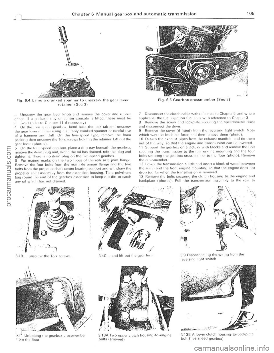
Fin. 6.<1 Usi",! a cranked spalliler to unscrew the goar Inver retainer (Sec 3)
Uus';",,,, 111" !I";)' '"'1''' knOiJ and ",lllOv,! 1he COVlJt
Fig. 6_5 Gearhox erossltH!lllhcr {Sc. ; 3)
'I 0,,,(I)I)I
:C1 the cl,,[r,h c
hn ekpl.,,!! (photos) Pull the ['.lI1SIlHS",OIl ;,sselllhly I() Ihn 'c;" 10
.,..
3.4C
).,
{" ; ",
3.13A Two upp.:. cllllCh houSIIlU-lO·engrne boilS (arrowed)
3 13B A lowe, clutch houslflg-lo·hackpl"te I)olt (I,ve'speed (JeJrbox)
procarmanuals.com
Page 107 of 205

·06 Chapter 6 Manual gearbox and automatic transmiss io n
disengilge the gearbox inpu t Shill! hom ,ho clutch p,Iot bearing ,111(1 clu tc h friction disc. I, is imporlanllhal,hc engine and transmi ssion <'lre kept in lino while this is being done. 14 When the gearbox shaft is cleDr of the clutch, remove th e
tran smissio n assembly from bCn(!illh the car.
15 When refiuing, ensure 1il1 the clut ch pilot h earing in the end althe tfilnksha h is ill plilce Jncl is scrviceDble. Tic the clutch lever 10 the clutch housing, 1 0 pr(!venllhe release le.rertrolll slipping out while the ,Wnsmission assembly is being lined. 16 Smear some molybdenum-based grease OntO the end and splines 0' the gearbox input s!mh lind refit the gearbox by reversing the fcmovili p.ocedure. 17 II is impO.IMll when offering up the {jOMOO)(. th,lt il is e~
slightly until the splines enter Do not iluempltO lo.ce the tfilllsmisslOn
ontO thO enlJlnO ThiS Illay (i
'8 Ahe •• el,uinn has been completed. chuck the 011 level Ifl t he .r
Romoye the lou. bolts hom the 1011 cove. 01 the t.ansm.sslon c~t()"sion housin!J ilnd f.om the lri"'snHs~ir)Ol eo'S<' Ilcmovflthc \:oye. s.
t.1king c
R emoYo the .eyerse idle , shah by sc.ewing a suitable bolt into Ihe end of Iho shah and then leye.ing the Sh;'lit Out uSing Iw o open ·ended spanne.s. Fi\)
.
6.6 Removing the seleclor 10lk rolillins (Sec 4)
A CIfC/'11
Fin. 6 .7 Revorso gear interlock nnd light swil c h (Sec 11)
A Ravelse liyh, switch 8 Swing C Plf/ngcr
o h!/ellocl< ball E Sc,ew IJlug
Rct.1ininy bolt F
5 M
thud gear lotwald lly lel/erinu the,n gently wrth a p
their condition. Smear all Pi/ItS wilh tr3nsmission 011 befo.e fitting .
9 Reassemble the synchroniser sleeve and hub so that the nlafks on thorn align . Inse.t the sliding keys and 1IIIhe shdrn\) key sp"ngs so Ihat Ihei. open ends afe stagge.ed re lat ive 10 each other
procarmanuals.com
Page 108 of 205

~
~ ,
~"i
~' .2
, Mil'" dfivc gear bearing fewincr 2 Gasket 3 Detent balls with springs 4 Transmission case gasket 5 Tfimsmission case cover 6 Speedometer pinion 7 Dowel 8 Extension housing cove! gasket 9 Ex/ension housing lOP cover 10 Selector housing gasket
0) ® (6 o I , ,
, i
"' t:< '
I , - \.f' -
(t!
,Wi 1m '~f" .'-../ '---" .... ......-t ' , ..
-----~:.---~
@@y314 , /
'" '". I-@
< i~@ -. .-.J.'
"...J\7' "'-', " . -,-;. , '\. .. ' --..,
~ .o.--? 0, .' '-;, ;:-~ \"'~. , . \~ .;; (3/--.,.~ ~1'\ . "~., . -,~" "~\_. \. ... " . , ~,
'i::
'r'" ~
F ·® (" ,J
J
I
- @
' \... . --; , >. ..~ . ./ j\,
' r<»., ~\ "":~" < ,
"
.. ..J ~, ' ...... .' ;". .~ . .-... ' ";:,;... '( , . -~ '23' " . I _./ _~,~ '.' _ .... JIi'"'"' •. ~ _",_ . ' ./.' 25' _ ..
; .. ' " .~'W
--<. .,y 'B Y ~ • --, 1 ":-'..., '~~ ,
<-.~ ~
ff,v ~30 ~ '.~, 32
@ < ,
. >
--®
1.20,
21 . ,
\< /22 , .
~" ; " "-,'
----@l . ' .
@
Fig. 6.8 Exploded view of four-speed gearbox casing and selector mechanism (Sec 4)
'I Selector housing cover 21 Selector shaft bearing support 29 Seleclor rail wilh 3,d/4th gear selec/or 12 Cap boll wllh lockplale 22 Reverse relay aIm foil pm fork
13 Spring 23 Bcaring sUPPOfl 30 Circlip
14 Delenl ball 24 Extension hOUSing gaSket 31 Plunger
15 Plunge! 25 Se/ecto! fail wllh 1st/2nd gear 32 SelCClor rail with reverse gear selec/or
16 Sprmg selector lork fork 17 Reversing light switch 26 Fiffer plug 33 Selector shaf( 18 Gear {ever assembly 27 Drive gear, bearing relainer 011 seal 34 Selector finger
19
Oil seal 28 Plunger 35 Reverse gear relay lever
20 E~tension housing bush
~'c:-.:cc::-:-.:c.:,.,· .. , . .... ,
~
~ 0 ~
灲潣慲浡湵慬献捯m
Page 112 of 205
Chapter 6 Manual gearbox and automatic transmiss ion 111
24 Chec k the plilY between the selector finger and 3.d/top geM selC{;lOr .a,1 (F,O. 6 .1 6) . lh,s d,mens,on shou ld be 0.9 mm (0.035 in). lo m"ke t he chec k. move the selec to. leve. up to the .everse gea. SlOp. Us.ng a lever. push 3.d/top gear selector .all \0 the rear and then
measure th e clea .ance by rnsel1lng leeler gauges betwee n 3rd/top gear selector rild "nd seleClOr finger. If th e cleM,mce 's no t ns specified. it shou ld he conecled by chnnging lhe .everse interlock geM plunger for one whIch will give the ,'PI).opria te clearance. 25 F,t a new gasket 10 the e~lension housing cover. Posilion the
cove •. ,nSOI I the fi~ing bolts nnd lighten Ihem 10 Ihe torque wrench Solt1inlJ g,ven in the Specifications. 26 M,1kc su, e th atthe geMl>o~ dmin plug is I,tted and tigh tened where apphc, 1hlc. then I,ll the uenlbo~ 10 the COffect level with the specl l'ed
,,'
10 Gcnrchnnge lever (4,sjleccl ) - m odificnlions
1 To ,mp,ovelhe \]flnr ch nngc movemcntlJctwecn lh(: Hea.s. , smallm CO".,r levcl Sl)!"'g ,s 1'lIr,<:I. the new 51)/,nU d,amclr'!' bc inU 20 mill (008 aga,nst the orig,n;r l sp.,n!) IIiarllctm 01 2.5 nUll (0 .1 0 inl.
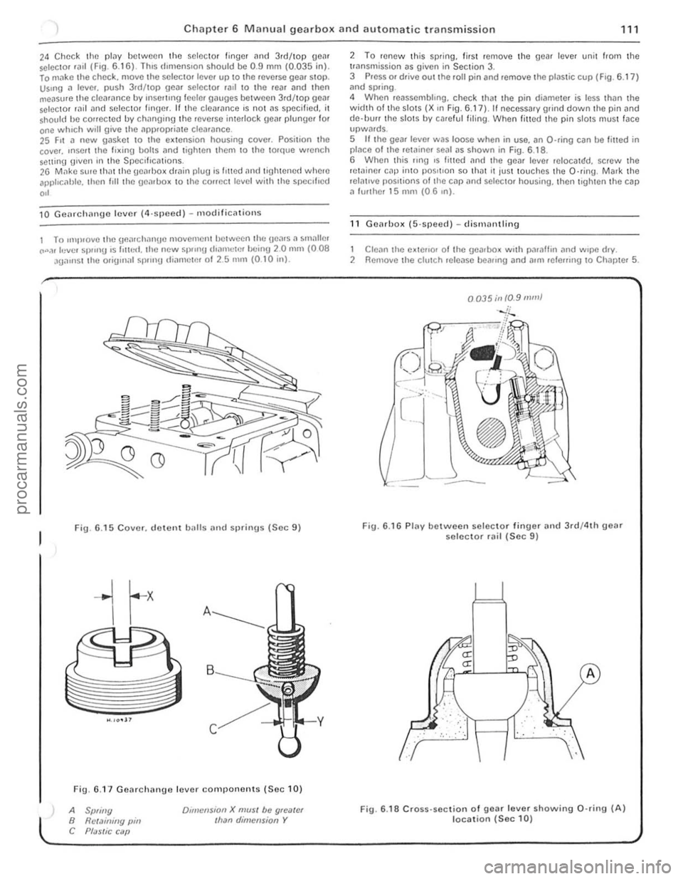
Fig. 6 .15 Cover. d ewnt balls and sprinus (Sec 9)
Fig. 6.1 7 Gearchange lever components (Se c 10)
A Spliny B Rct.1illiny pin C Pf;JSlic C ilP
Dlillcnsion X mUSI be gloater Ilran dimension Y
2 To renew Ihis sp.ing. lir sl remove the gear lever unit from the trnnsmission as given in Section 3. 3 Press or drive out the roll pin and remove the plastic cup (F ig . 6.17 ) ;rnd spring .
4 When reassembhng. check that the pin di('!meter is less thiln the width 01 th e slots (X ,n Fig. 6.17), II necessary grind down the pin and
d e·llUrr the slots by ca.e ful filing . When filled the pin slotS mus t face upwMds. 5 If the gear leve. was loose when in use. an O-ring can be filled in placo o f Ihe retainer sOill as shown in Fig. 6.1 8 .
6 When this flng ,s fmed an(I the gear leve. reIOCalr:!d. screw the retainer cap inlO pos,tlon so th ilt It jus t touches th e O·ring . Mark the relntlve pOSitions of tile cap
1 Clean the e~tello. 01 Ihe gearbox w.th paraffin .,nd w.pe d.y. 2 Remove the clutch release beallng and allli lele",ng 10 Chapter 5.
0035;11 10.9 mill}
Fig. 6.16 Plav between selec to r finuer and 3rd/4th geM selector rail (Sec 9)
.. : . :,'. :", .
fLJ
··· ..
A
Fig. 6 .18 Cross· section of gear lever showing 0 ·rin9 (A) location (Sec 10)
i
i
procarmanuals.com
Page 115 of 205
Chapter 6 Manual g ea rbox and automatic transmission
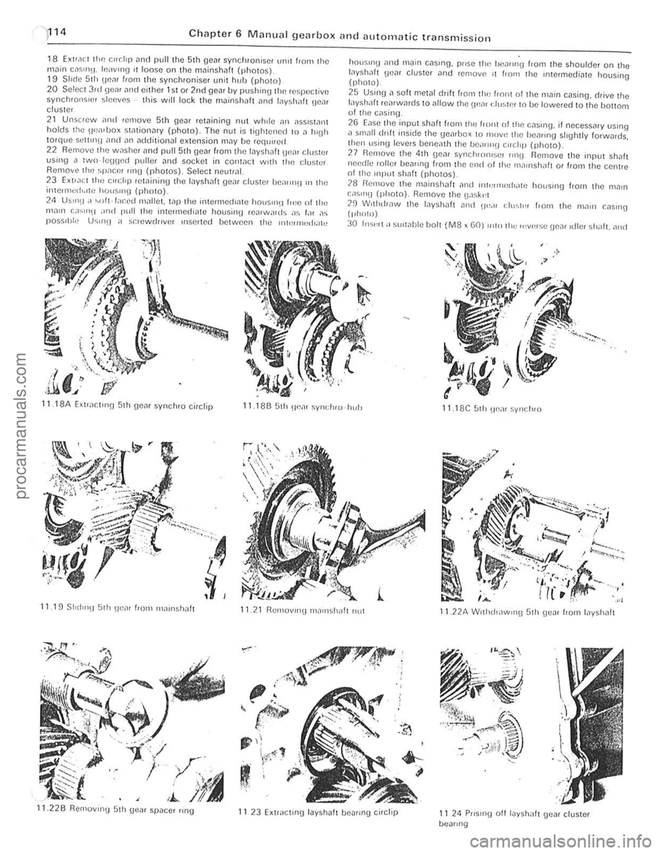
18 EXlra ct the r."dp and pull the 5th gcar synchronise r ur1lt f'orn the
rnn in c,lsm\1. Icavlllg I t loose on thtl mninshaft (photos). 19 S II(le 51h IlcM from the synchroniser unit huh {photo) 20 S elect 3rd gem and either 1st or 2nd gear by pushin\) the re~peclivc synchronsrcr sleeves this will lock the mainshllft
24 US"'(I;' ~oft·f;,r.ed Ill;-rllm. wp the intermedrate hOtJS"'~1 (,,!e of tl,,; ",<1111 c
.I,' ,i.li. J
hO(lSII1\1
layshilft rearwards to <11101'11 the \ .wm d,,~tn' t o he lowered 10 the hottoot 01 tlHl cas,,'U .
2G Ease tlte input Shaft f'om the frOllt 01 tlHl c;-rSlng, if oecess
29 Wllhdr,lW th e I,lyshalt ,11lel 0"_" eh";t,,, I,om Ihe 111<1111 C;-rSlIlg (phOlO)
30 In:;'''I; ' sUlwble bOl t (M8 x GO) Illto Ih" ,,,v',,:;c !Je,1( ,die, shnft. alld
11 18A Exlrar.t,nn 5th geM synchro ci,clip 11.18B 5th u em syl,(IHU hul) 11 18C 51h ~Je;-rr synclH O
11.19 SlId l"!J 5th !/tlar from "'
Page 122 of 205
) Chapter 6 Manual gearbox and automatic transmissio n
121
"
i
...,
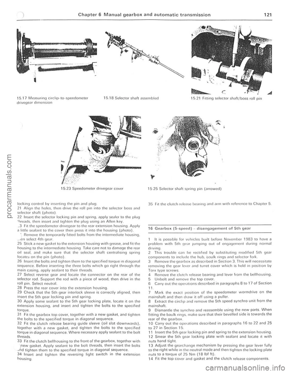
1 5. 17 MC~Sll"nu corchp· 10·SPCI1(lOIllClcr drivcgc,l' dImension 1 5 .1 8 Sc lcCl0f Sholl! t1sscmlJ lcct 1521 FIlling selector sh1lft/boss fall pin
15.23 Speedome ter dJlvcgcn, cove.
IOCkmg cOI1l,ol hy Inserl;"y the 1)111 ;lnd 1>lu9 2 1 Ahgn the holes. then (lillie Ihe roll pin il1lo the sc lcCIOf boss ;111\1 SI~ICC1Of s h
main c .. sing ... pply se
29 Check that the 5th gea. interlock slceve is corrcctly .11ognoo. then 'nscrt thc Sth geil' locking pin and spring.
30 Appl y some scalallt to the 5th geilr locking plate. 10Cilte It on thO extensio n housing. an d inselt nnd t igh ten th e bolts to I h e specIfIed torque. 31 Fit the Ueilrbo~ top covcr. together WIth a new gas\(et. and lighten
the boilS to t he sf1eclf.ed tOfQue in diagonal sequence. 32 F u the clulC h relCilSe bearing guide sleeve (oil slot dow nwllfd s). together with a new gilsket. and lighlen th o boi lS to the specillt~d torque in d;ilgon;11 sequence. Where neceSS;1ry apply seal,.nt to the bolt threads_ 33 Fitthe clutch bell housing to the Iron t 0: the gearhox. together woth new gaske t. Apply sealant to the bolt threads. thcn inse n the boilS .~d tigh ten them to Ihe SIXlcllled 10rQue in diagonal sequence. 34 Inscrt and trgh le n the .ev(usinl.l Ioght switch in Ihe ex tensio n housing
1525 Selec tor sh aft spring pin (arrowed)
35 FIt the clutch reLease l"l'lIIng and a.1Il wuh .efercnce 10 Chnl)\ el 5.
16 G e(lr box (5-spee{l) -d isellg i:lgem enl of 5th gear
I I
is possI ble 'or vducles hu,l t bclo.e NovcmiJer 1983 to have i:l p.oblem WIth 5th ne". Illillplllg Ollt of cnuanClllcn t during normal
(hlv lnu
2 ThiS 1I0uhle Cilll he rcc tl',cd hy suhstitutinu nlod,hc
3 Rem ove Ihe gearbo_ "s de$("bed in SectIon 3. This wrll nCCCSSlla te lemov ing the ge(l' Icvcr "nd lu"C I cove. whIch is held In ,)OSltlo n by TOOK typc sClews . 4 Removo the clutch Hlleilse bearing and tevcl 110m the bclthousing . 5 Unbolt ami lemovc the lOP covel. 6 C"ory out the opel,1t'0"S dcsc llbed in par "graphs 8 10 1" 01 Seclion
" 7 M"r\( Ihe ex.1Ct IIOS""o n of t he speedometcl wormdrive on the milinshil lt (lnd then draw it off using a pulter .
8 Extr"ct the ci. et,p "nd H)move the 5 th sp(lcd sync hro unil/rom Ihe
mJinsh"lt. 9 Dismanlle the synr.hro "nd reasscmble using the new p" rts, When I Itting t he b"ulk lings. m"ko sure that theil bevelle( 1 side is tOwa.ds the
re,,' o f Iho ge",box. 10 Caffy out the ope,,,,,ons desCfibed in jh"lfilgraphs 16 to 22 and 25 1027 in Section 15. 11 Inser t the 5 th ge
procarmanuals.com