1974 FORD CAPRI wheel bolt torque
[x] Cancel search: wheel bolt torquePage 56 of 205

7
Chapter 1 Engine
Fig . 1.1 8 R ear oil sen I ilnd ildaptcr pliltc (Sec 84)
84 Renr oil se;1i ,,,,(I lIywheel - rc fitti"u
1 I'll the ()n!J"I(~ .r,," ,,(1"1'10' pla1<:1 and s(:clIre ,I wllh 'I S IIv(: holls. 2 Smenr en\J1ne (ld OlltO the CI,mkshah '''". Smear 0,1 on the lip 01 the sea l tlnd pos(( lon tlon ';".11 on th e cran hha ll. 3 Align the seil l c;""er holos wllh Ihose 011 the cylrnd(:, hlock . Insell the loul bolts and 11!lhlCll Ihem 10 the SpeCifIed 10lqUfl 4 F it the flywher.:l . or dllveplalc on au lOlllallC lwnsrnis sion Illodels.
InSerll h e six holl S ;",d u\llole rllhem 10 Ihe 10 lque w rench sell"'U Uiven in lhe Speclllcm'olls
8 5 Sump -rciiuill!)
En~",,, lh;ol Ill" ru,rI "'!) ',u.l,u :e s 01 hoth IllI.! Slimp a"d t h e c(,1nkcilsc ,lie cl ea" ,mol IIi,1I n", '.""I",!) SlIrJ ,u;e 01 the Sli mp IS not d'S lo lte d. 2 Apply IO" ,I,,,!! c"'''pollnd 1 0 the pOUltS wllel(~ Ihe l"llllll) cover ablilS lhu ,;yir r"lr" 1,Io ck .lIId where Ihe rea' 001 $u,,1 carr.(:r "dIOIllS II 3 Pln ce tloo \J,,~k"l '" fJo~.t.on, lIt tlo" SlIm l} ,'Ild IIlS(). 1 lhe r0Io1111il1l)
bolts ImUO I tl!lhl 4 PrO!lres~lvely 1I!llIt,," llw sump holt s 011 opposIte I'ilr ts lIllt,1 all 0 1
t
hem ,H" il l tl", ~ 1"":lllI"d IOlllUU , 5 FII ,1 now w;,~h", 10 Ihe ~Ul1lp II"'UI pili!) , IIlscrl lhe dl,lIll pllll) and
t ,uhlen ,t
8 6 Cylinder h e"ds re;rssernbly
L~y the cylrnd" r h",.\! on .IS s Ide. luhrrcnt e cvcry valve Uu ide with eng;l1(! oil. ,lilt! ,"~,,"t the valves 11110 the \Ju, dc Irom whIch lh ey wele remov(:d 2 To ,WOld d
lhero.s dilnlJC' oltl1<.: ~I""IU rcW""C' dillllil\)IIlU tllC villve SHlm 011 sen l
G Ahcr "lsert")!J tit" ~pllt collets. r eleilSo the spllny compressor (111(1
rcmove II 7 C hcc k th"t lh..: ~pl'l cull":IS hilve seilled properly and t
Fi g. 1.1 9 Tightening sequenc e for cylinde r head bolts on the 3.0 litre enuine (Sec 8 7)
a Repe"l liln pruccdwn orven III p;ua!Jrnphs 1 to 7 o n the (CmJlnlllU
v,llv"s
87 Cylinder heads - re fitt;nu
11 the tappels w ere rcmoved. luiJricnle lhe lilppets nnd I heu hores wnh enoine orl nnd insor t thOlll wilh lhc;, d Ished cnds uppermost Ensule lha l every tappet ,s rclltlcd Into lhe hore hom whIch II wns
t nkcl1
2 Mak e sure tha t Ihe rna t"'!1 surlaccs o f lhe cylinder block. cyl lndor henrJs ;Uld 1111,,1 Ill,lIlIlold ;lIe de;"l. then plnce new cyhndcr head \Ja~kets ove, the Wildes un thn cylrmh" block. Tho cyirnder head \I,,~k ~IS beilr thO malkln\! TOP f:nON T ilnd nced to h e pOSII,oned
cOII(:ct ly .
3 Low ul Ille cyl ""lcr he,1ds ov"r the" posl tlonrngst u(!s, Although t he cyhlld\~r headS ,"0 Id entlc;,I, they should h,lVe been Illtlrke d when remuved ilnd should be lehllUd III thcrr ()IIUinal positions t1 Inse rt the cyirndcf 11I)"d boilS f"'!I(:r t.!Jh l then tIghten lhelll prUglC SSlv(: ty OIl the olde, shown III r,U I l!J and III llle stnucs",s U iven
m the SpcelirC;lt'OnS
88 Rocker arms and cover
s -refiUing
Ensure Ihm "II Ihe puslllOlls ,lie ,nselwd I!ltO the" p'llpor placos ;II1
)olt S nntl lighten them t o the spec ,f led torque.
89 Valve clearnnees -checking nnd adjustment
R eier
to SeC!lon 3 5
90 Engine ancillaries -refitting
R eier 10 Sec tIon 46 and ref, t lhe I. ste d componenlS w,th refercnce
to th e Chaptels ind,cilte(f
procarmanuals.com
Page 98 of 205
Chapter 5
Contents
CIUICh il$scmhty '"SIJoCcl'Qn . Clu\(;11 assembly 'Urn!!ll!) Clutch llsscmhly lemOY," C lutc h cilhle .efluwal._
Clutch
Clutch !Jedal rClllovnl illld ,cflltl"U
Specifictions
Genera l Type ..... Clutch (lise (hamClcr lining tlnckncss Clutch pedal hcc "
Gene.al description
,
5 3 1 8
All manu:!1 transmission madllis covered by this manual nrc lilted Wilh a singlo dl3phrilgll SpllJlg clutch. The unit COlllt)riscs il steel cover which is dowelled and bolted to the tear lace of the lIywheci ilnd conla i.lS the pressure plnte. diaphragm spring and fulCrum .ings . The clutc h " iClio n disc is
ee to slice along the splineJ gearllox
Inpu t Shillt and is held in posi t,on between the flywheel and the pressure plate by the pressure of the pressure plate spring , Friction linIng materiill is riveled 10 the d,sc and II has a spring cushioned hull to absorb transmission shocks and to help ensure a smoo th take oft. The circular diaphrilUm spring is mounted on shoulder pins ilnd
'Ield in place in the cover b.,. two fulcrum rings . The spring is also held ,0 th e pressure platc by three spling steel clips which are rive ted in
posi tion .
The
clu tC h ,s aCluated b.,. a cable controlled b.,. the clulCh pedal.
Clutch '0Ie,150 bCilfl"U -remova' and wl,u,"g Filult (ioilU"OS'S -clutch Generill descllptlon . noutlilc rn,untenanco .
SlIlgle (Iry plate. dlill)hragm sprong. cilhle ·ope.ated 241,3 rnm (95 Ill) 381 nun (0 15 In) 27.01 40mm (1.OG:i 0 .16,n)
No. Ib l It 16 to 20 12 10 15
G 9 1 2
The clutch release mechanism consists 01 a .elease leve. and a bearing which conwcts the lelease Imgers on the pressure plilte assembl.,.. The eHect of an.,. wear of the friction ma terial in the clutch is adjuSled out b.,. means 01 a cable adjuster at the lowel end 01 the cable where it
passes through the bell housing .
Dep.ess lng the clutch pedal actuates the clutch release leve. b.,. means of the cable . The lelease level pushes the lelease bearing
forward to bear against thO release l ingels so moving the centre of the diaphf()gm sprong within the annular rings which act as fulcrum points.
A s th e centrO of thO spring is pushed in. the outside of the Spling is pushed OUI. so Illoving Ihe pressure plme backward and disengaging the p.essu.e plate flom the /tielion disc . When the Clutch pedJI is Icleased. the diaptllaglll spring torces the plessule plate into contac t w ith the frictIon linings on the d,sc and at the saIne t,me pushes it a flactlon 01 an InCh fOlward on I\S splines . The
disc is now fuml.,. sandwic h ed between the plcsswe plnte Dnd the
flywheel. so the d.ive IS laken up.
procarmanuals.com
Page 136 of 205

m
)
Chapter 8 Rear axle 135
Fig 8 .8 Drilling the beMing rf!t
5 AxlcshiJft homing -renewal
Noto: A SfJL'CI.1f 1001 IS "Hlliller! /0 n'III1:''''''[1 (,0111 lilt' axles/mIl (s,:c Fly 89) 1 Remove the ;,xlushalt as ,h:sG"hcd 1(' St;CIl0n 1 2 Usin\J all 8 mill (0.31 In) dldl, 1Il;,kc a hole III the he,Hlnt! ,etauun\1 119 . t
G Cleiln the l1xlcshnf1. be,non\) ,,,t;WlC' ,Hld "xle C.,1511l\) 7 Locl1le the loe1ll1ll9 HIWlIlel 011 the l1xleshl1lt. followed uy tho new uoa,ing wIth the 001 sel1l [l1CIll\) l1WilY ['om the l1~leshaft Hallge. 8 Slide on the new hea'lIl\) rcta"lIn\) '1119 and pr ess J fully 11\l111l1st tile hearing inner IWck. uSIng a slJItJIJle puller or J ICWlth oftuue. 9 Re fIt Ihe l1xleshalt wllh refe'ence to S ectIon <1
6 Axle reM cover relllov,,1 ilnd refitting
Chock the hont wheels then lilck up the re,l( o f the Cl1r il'l(l SOPPOI1 on axle stands.
2 Cl em1 the reM cover .Jnd surroundIng .Jre" (photo) 3 Remove the hllmlbr"ke relay le ver lind seco nd.Jry cable. or
transverse ,od (as ;;Jpplicilblc) with reletCnce to Ch"pter 9. <1 Place a suitable container helle~th the reM "x Ie to c~tch the oil as the rear cover is removed.
5 Undo and remove t he ten IJOlt s and sprinU washers lhilt securo the reill cover to the llIl,l l drive housillg LIlt aWilY th e re"r cover and its
\Jasko!. ~ Before refitting the ,oar cover Illilke sure thm the mating fJces ilre free of th() old Uaskct or 10nlting compound.
7 FIt a new uasket Jnd then the lea, cover and secure wIth the ten bolts and spring washers. The cover bolts protrude IntO the fillal drive hOUSor1U so it is important that a SUlwble oll·resist.Jr1t scaling
... __ ro*
Fig. 8.9 Usill(J the special Ford tool to removc the axlesllilfl henring (Sec 5)
r;olllpoulid IS SlIll:ilr() d onto lioe Ihro,'ds of each boll bef ore it IS [,twd. 8 TIUhwll tllr: cover secu,,"!.! holls 10 lhe spec,[,ed torque Wfl:IICh
se ttln\)
9 ReCOlillect
Iht! h,lndbr,l~e components with re ference to ChJp ter 9. 10 R efil l ti,e 1e;1I ,ule with the correct 9rJde 01 oil then lower the C,lr to
the UIOUIl(i
G
2 Axle reM cover
7
Pinion oil seal -re"cw,,1
This ope r,ltion may be performed WIth the rear axle in position or on
the benc h
2 Undo ~nd remove the two holts. sprinU Jlld plain washers that secure lhe centre bearing support to the under51(fe of the body (reler to
Chapter 7) 3 With a sc"ber 0' fde. Ill
propeller sha h to ttt() flool I I
J m
procarmanuals.com
Page 140 of 205
•
Chapter 8 Rear axle 139
ci,cumS«"Ulces mny only one pmt of the two be renewed. fnspect the dllfe,enti,ll pinions nnd side gems for signs of pitting. score mMks. Chipping nnd general wem. Obtain new gears as necessa,y . Inspect the th,ust washers lor signs of weM or deep sco,ing. Obwin new thrust wnshe,s as necessary. Once the pinion o il senl has been disturbed it must be discMded and a new one obtained. 20 When new pnrts have been obwined ns required. reassembly cnn begin. First lit the thrust washers to the side gems and place them in position in the differential housing. The ground side of the thrust washers IllUSt lace the side gC.Jrs. 21 Place tile thrust wilshers behind the dillelentini pinion genrs i1nd mesh these twO Oems with the Side gears through the tWI) ilpertores in the lilllerentlill housing. Milke sure they ilre diametlicilily opposite 10 each other. RO«l!e the clillerent'i11 pinion gears through 90' so brinUlI1\j them into line with the pinion genr shnlt bore 111 the housinlt 22 Insert the pinion genr shnft with the lock In!) p'n hole III line with the pill hole. 23 Usinu leeler 1),IU!Jcs. measure the en{lll(",t 01 ench s,de Be,,,. II the speclficd h\Jure IS excecrt"d. IU!W tl"u~t washlllS mu"t he olJt,uned
-omnlllie the a~~el)lhly ,lg,llll ,trld ht new thll,st wa:,lu'
28 Using soitable diameter tubes. fit the two Wper roller bearing cones into the finnl dlive housing. making sure that they ale litted the correct way round. 29 Slide the shim and spncer onlO the pinion shalt and insert inlo t he final drive housing. 30 Relit the second and smaller diameter wper loller bea,ino onto the end of the pinion shaft lind 101i0w Ihis Wilh a new oil seal. Sefore Ihe senl is nctually fitted. apply some grense to the inner Ince between the two lips of the seal. 31 Apply n little jOinting compoond to the outer Ince of the seD I. 32 Using n tuhulilr dllft 01 suitable dinmeter, carefully drive the oil seal into the fillal (hive housinlJ. Make quite sore thnt it is lilted squarely and flush with the housinU. 33 Refn the drive pinion IInnge nnd hold securely in n bench vice. It II fixed lenIJth spncCl is Itlted. fit ilnd tighten the pinion nut 10 the spec ,lied lorque. If a collapsihle spnce r is f,tte d. follow the prOCedlHe
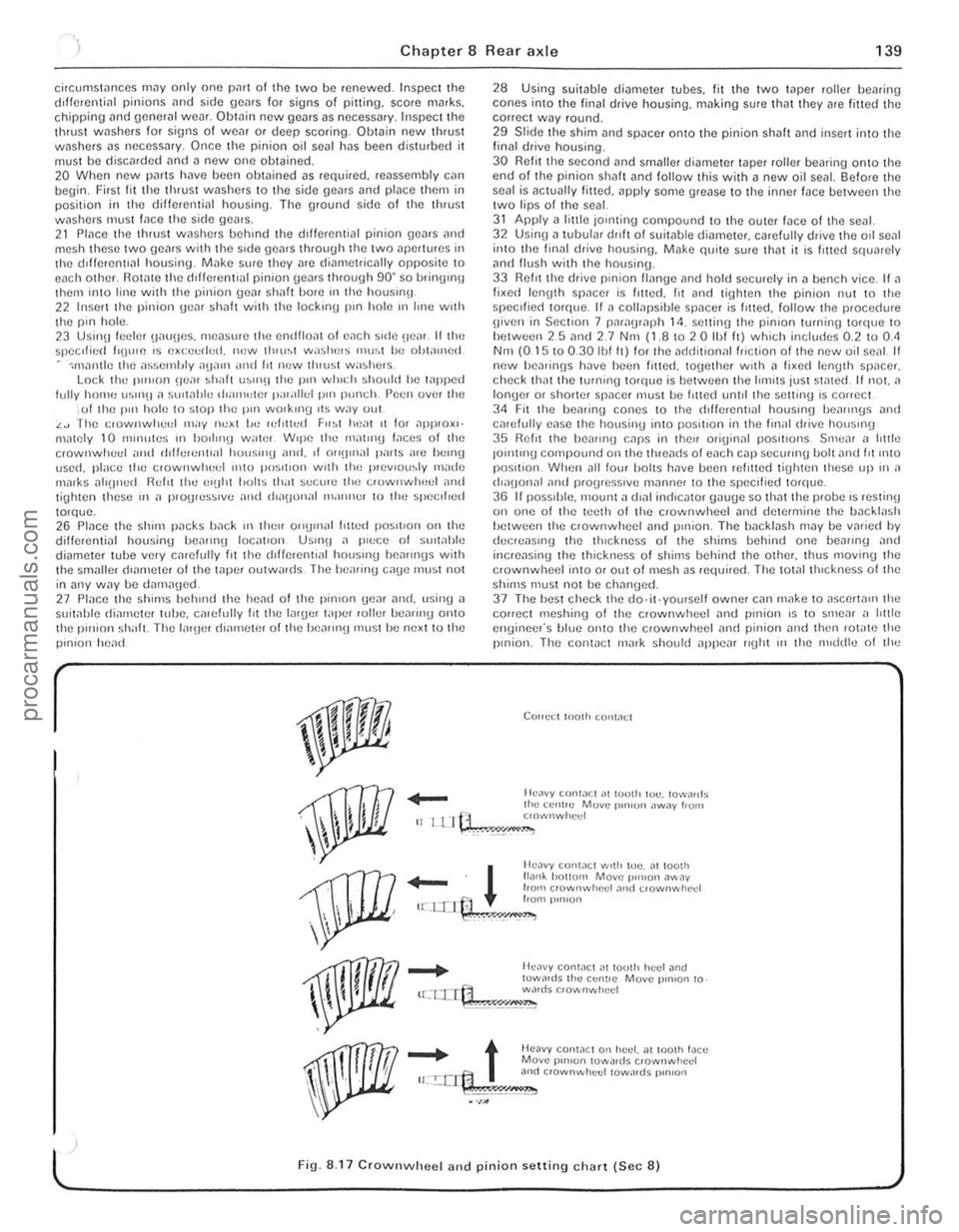
g iven in Section 7 paragraph 14. setting the pinion turning to'que to hetween 25 nnd 2.7 Nnt (1.810 2 0 Ihf It) which includes 0.2 to 0.<1 Nm (0.15 10 0.30 Ibl It) lor the ndriitional friction of the new oil senl II new hea,inns h~ve heen filted. logether With n li~e(l len(Jth SP,lCer. check thm the tOrlllllg torque is bel ween the limits just stmed. If not. a longer or shorter spilcer must he I,tted until the setting IS correct 34 Fit the healing cones to the cf,fierenllal houslIlg heallll(Js and carefully ease the housing Into posilion in the finill drive housmg 35 Relit the be,IIII'!J CilpS in thell originnl pOSitions. Srnc,ll n httle JOlntmg compound on the threilcfs 01 each cnp secuIII'O bolt nnd fit 11110 position. When ,111 low halts have bcen rein ted tiUhten these up in a (h"IJonal and progresSive milnne, to the speCi fied torque. 36 I I pOSSIble. 1Il00nt n dlnl in(licntor onu(Je so thnt the probe IS resting on one of the teeth of the crownwheel and determine the backlash hetween the clownwheel and pillion. The bileklash may be vMicd by elecreasll'\) the thickness of the shims bellind one beilling nnd incrensing the thickness of shirns behind the othcr. thus moving the crownwheel ;nlO or out ofmcsh as requi,ed. The tOt.llthlckness 01 the shims must not be chnn\)ed. 37 The hesl check the do·it·yourself owner cnn make to aSCerta", the correct meshinu of the crownwheel ilnd pinion is to smear ,I htt le engineer's blue onto the crownwheel and pinion iJnd then lot"te the pinion. The con1
_
t Heavy conWCl 0" huel. at 100lh !,leu Move p'",on lowa,ds crownwhcd u:.!:.crt:1 3nd c,ownwhuel towards p,n,on
.~\;!~" •. ,;.';,;,"",.,=,"--
l ' Fig. 8.17 CrownwheeJ and pinion setting chart (Sec 8)
, ,
, ,
"
procarmanuals.com
Page 146 of 205
) Chapter 9 Braking system 145
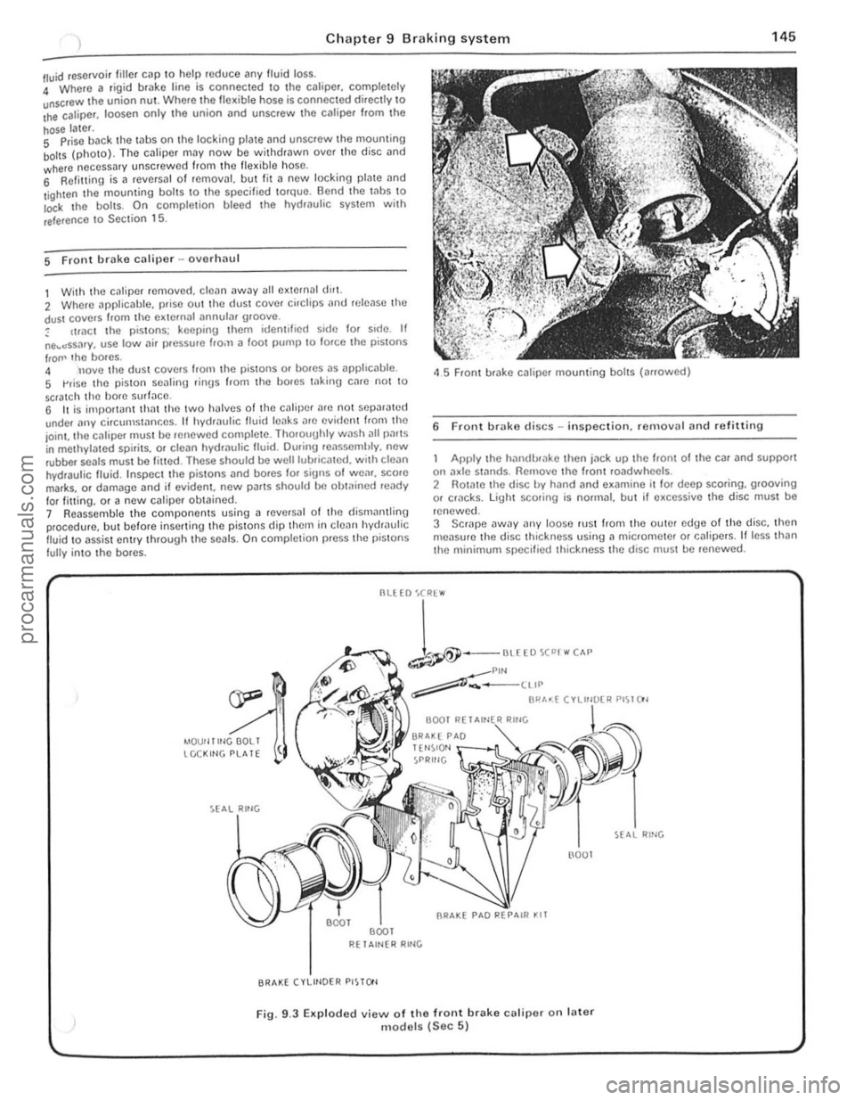
/ll.Iid reservoir tille , cap \0 help roduce any fluid loss. 4 Where a rigi d brake line is connec ted \0 the calipe r, comple tely unscrOw the union nUl . Where Iho flex ible hose is connected directly \0 Ihe caliper. loosen only .he union (lnd unscrew Ihc caliper f.om Ihe
hose later. S Prise back the laus on the locking plale and unscrew Ihe mouming boilS (photo). The cJliper may now be wit hdrawn ove r th o disc and where neCessary unscrew ed from Ihc flex ible hose, 6 Refilling is a revCfsal of fernOv;!I, but lit a new locking plate and
l ighten the mouming bol ts \0 the specified torque. Bend the Inbs \0 Io<:k I he boils. On comple tion bleed the hydwulic system wit h
reference \ 0 Sec tion 15.
5 Front brake caliper -ovorlulU l
1 With the c~liper removed . cle~n away all external dlr1. 2 Where applicable, prise out the dust cover cirClips
IrOIl' lho bores. 4 nove tho dust covers Irom the pistons or bores as apphc
45 Front brake caliper mounting bolts (arrowed)
6 Front brake discs -in spection. re rnovnl and refitting
Apply the hilndlxake then jn ck up the hom of the car and support on :1xle st:1flds. Remove the Iront roadwheels . 2 Rotate the disc by hand and examine il lor deep scoring, grooving or cf1lcks. light scoring is normal, but if excessive the disc must be
renewed.
3 SCrJpe
--
1-""£0""""" ~Plf'l ~-____ ttIP
BI"'~( ".",~"" PI~I()'
4IOUf llltlGOOLI tCCKltlG PLATE
R( 1 Altl{R RltlG
BRAKE (VLIHOER PISTO'l
(l001
Fig. 9.3 EKp loded view of the front brake calipe( on fater models (Sec 5)
RING
., .,
,
procarmanuals.com
Page 147 of 205
Chapter 9 Braking system
4 Note that in order to m,lintOIll even braking both discs should he renewed ill the sal1 1 e lime
5 T o remove il dl~c. first remove the tHlb as described in Chllpter 10 . 6 Prise lip th(J locklllU I"hs. unscrew the fOlll bolts. and remove the disc from Ihe huh.
7 Clcilll the Illllirnu !ilces of the disc and hub then locale the diSC on the huh and allgel the holt holes.
8 InScrt new holt~. tOI){)ther w rth new locking plates. and tiuhten them to the specrfre(1 torque_ loc k b y bending the tabs. 9 Th e huh Illily now he ref Illed with reference to Chapter 10.
7 ReM hrake shoes -rt)rlewal
Check the front wheels th!:n lilck up the rem of the CM lind support on ,1~le stands. Rel(,a5e Ihe handbr,lke lind femove the reM roadwh~~els
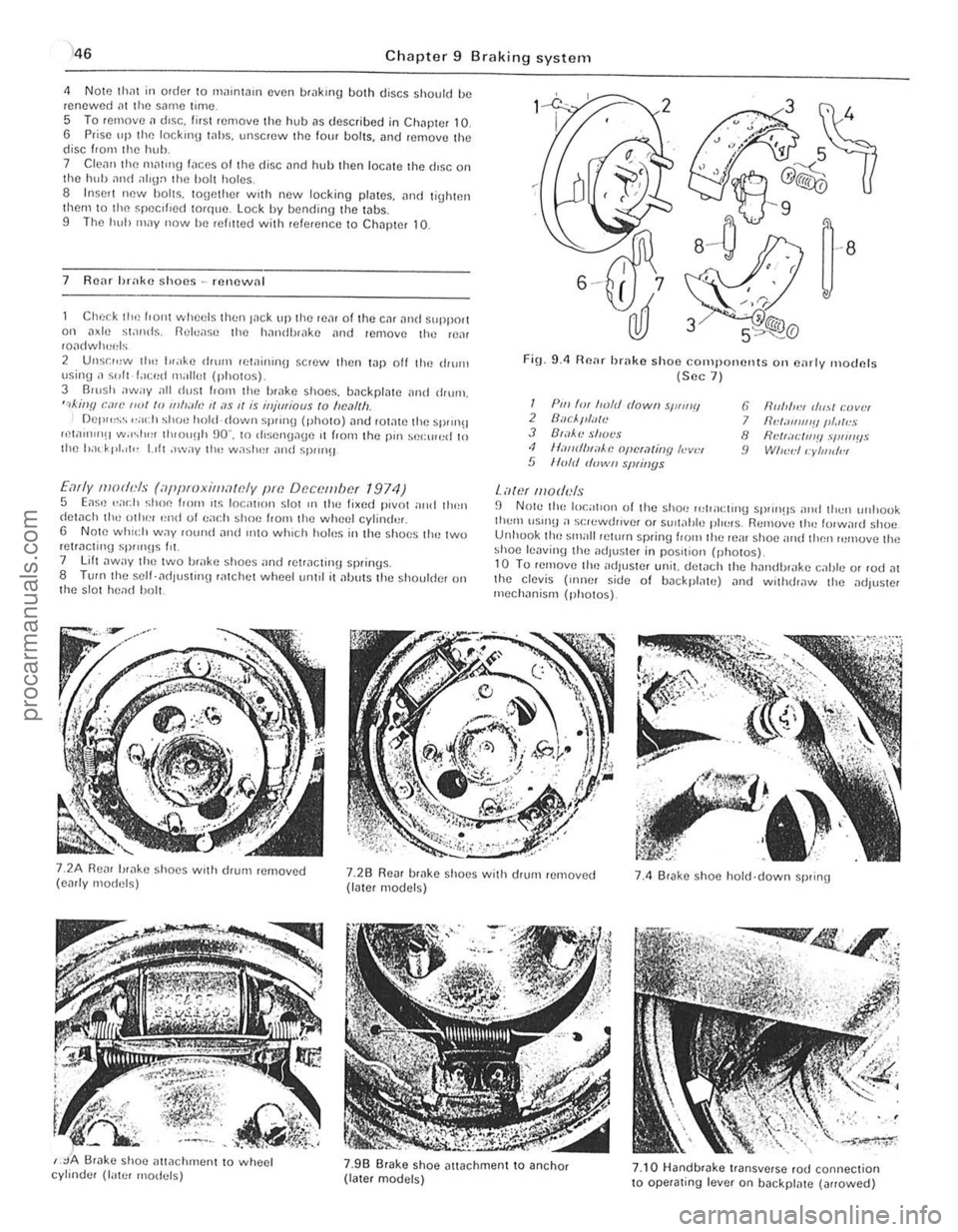
2 Unsr",w th" I"ake drum lewinrnu scrow then t.1p off the ,IIurn \Jsing ;I ~"It f.lced milliet (photos) 3 Barsh away all dust I.orll the brilke shoos, backplate ilnd drum, ",killfl can' ""I /0 11111""., II ;I S 1/ is iHjmiaus to "e,11Ih Del""~~ ,,;och shoe hold-down sprrng (photo) ,lnt! rOt,lte the sprrn!! ",w"nIlH w.r~I"" th,ou!lh 90" , to rhsengage ,t from the pm sel:rr",d 10 Ihe had' pt. 'I" 1.,11 ,"wily 1Ill! w;'shel and spm}!J
Early moth'ls (iippmxilllawly pm Df!c()tllbcf 1974) 5 Eas,) .. ad} shoe loom ,t~ loc;rllol1 slor III the lixed pivot nrrd tllen detach th,-othe! '~nd 01 ea(.11 shoe f,om the wheel cylind'lr, 6 Note whld, W.1Y fOwul and IIltO which holus in the s hoes tlH~ two retracting sP""Hs Ill. 7 lift ,lway t ho two brake shoes "nd retracting springs. 8 TUf(lthe self- ad lust'ng ratchot wheetum,1 it alJuts the shoulder on t he s lot head bolt.
FiO_ 9.4 Renr brake shoo components Oil e,lrly moclnfs (Sec 7 )
I Pili 'm froft! dowII sWIIIII 2 Buc/."liTlt! J B',l~'l! shot's <1 II,-IIIrflHiiAe opcra/jllY h-v", 5 lIo/d d"wII slNil/ys
Lawf lII oduls
6 fir"",,:, (/",,1 r:lJvlH 7 IId;III1I1'!IIII.llr!S 8 flNr;Il:IIl'!! .,'I,"IIIIS 9 WI",,:II:yllJldl!l
fJ N Ole the local,on of the shoe 1"lpacl,no sprrll!ls nrld thell unllook tlwm \lSUl!l a s(;lewrh,vef or SUil;!tJle plo~"s. Remuv,) th" lorw,lrd shoe Unhuok tho small pelurn spring loom the reill shoe and then rumuve the shoe lenvinlJ the adJus!Cr in pos,tiol} (ph o tos)_ 10 Tu remove tim adjuster unit. del
,
j
procarmanuals.com
Page 165 of 205
Chapter 10 Suspension and steering
~ l"Nfl> BUS"'''G
~ TRACK CONT~O~ AIIM
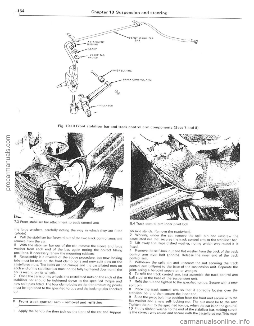
Fig. 10. 10 FrOllt st
Front Slilblliser bJr iltlilchmCIll to tr
5 With the stilbiliscr bilr out of tire Cilr. rernovtl the sltltlve Jlld lilrge wnsher from each end 01 the bar.
7 Once the car is on its wheels. the c(lsteli,lted nUlS on Ihe ends olthe st,)bifiser bar should be tl\[htened down to the specIfIed torqlJe .. nd new spill pinS filled The four cl(lmp bOilS on the IranI mountinu poinlS must he tluhtened 10 the specliled torque and tile lockIng whs knocked up.
P
Front truck conlro l ;lrm -removal alld refitting .
Apply the h'lIldl.>r
on a~le swnds. Remove the roadwheel. 2 Working ullde! the C(lr. remove the spirt pin (lnd unscrew Ihe cilslellmed 11111 Ih"t secures the trilck coniroi
5 WithdrJw the split pin [lnd Ullscrew the nut securing the trilck control Jflll battlOIl1 10 the base 01 the suspension unit. SCpar[lte the joint. using n ball,oinl Sepnr[llo,. or wed(Jcs 6 To ret, I thc lI"ck conlrol arm . fllsl JsscOlble the track conlrol [lrm bJIl stud to Ih(~ bilse of the suspenSIon !m't 7 Reflllhe nu! ilnd tighten to the speCIfIed torque. Secure with a new spirt pin.
S Place the track control (lrill so IhJt il conectly locates over the sliIbiliser hJr nltd then secure the iIlller end.
9 Slide Ihe pivot bolt into pOSItion "0111 the "onl and sccure w ith Ihe flat washer Dud il new scll.lock,no nut. The nut must be to the rear . Trghten the nUl to Ihe specified torque. when thu car is on the ground. to Fit the dished washer to the end of the stabll iscr bDr. making sure it is the cOllect way round and secure wit h the cas tellated nut This must
-------------------------.. procarmanuals.com
Page 166 of 205
Chapter 10 Suspensio n and ste e ring 165
he IllJhlCned when Ihe em IS on Ihe '1IOUI1(1. \0 Ihe speclhe(1 100quO Lock Iho cnSlC\lnlCd I1UI wllh n new spill pin.
9 Renr shock nbsorbcr -rClllovnl nlld rofitting
Early models 1 Remove Ihe bnck sent.
.pholo)
. models ~, CIlr:ck the front wheds Ihun F":k up th,) rca r olthc (:;" and SUPI"lI l on "xle swnds. tCmovH Ihe ,o.ldwlwel 10 Unsc,ew Ihe nu(S Iron' tim lOp 01 III" ~hock ilhsnrhe, ilnd ,,:move the wa~her and ,nsul"l!)r rllhh,,,. 11 Unscrew nllll ,emove Ihe hollom IIH)l1ll1l"~1 holl and wllhd,.lW Ih(, shock nhsOliJer trom the cnr. Now tlw 100:"t,on of Ihe Sllacr:, '" II",
1110ul1lll1g lubber. 12 If nocessmy (he moun(lng lUhbers IIlay be relwwed sepal;l1cly 13 Relittinu is il reversal of refllov
C
hock I hl) hOI1l whl)l)ls then Inck up Ihe rl);11 of Ihe cm nntl SliPPOlt
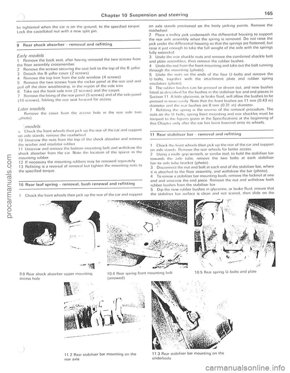
98 Renr shock ilhSOlbel upper mOIJnlln\j
nccess hol e
"
-----------_.-
II 2 Re~, stabi llser b ar mountinu on Ihe rear a xle
on
U ·lJol ls. 10'1",1"., WIth Ihe all.lchment pl,110 ilnd fubber splinf)
Insulatols (1,1",11') U The I(lhll'" Ilu~h"s C;\l1 be p,es'>vd 01 dl1ven oul. lind new bushes fllted ns {I",.( ·"l,,·d 11)1 Ih" hushes OIl Ihl! s!ahd ,se r bnr lind end pieces in
SectIon 11 1I1r1l1t~ !lIY CI;"nc. or I,,"kr, flUId . WIll
R eM st"hiliscr har -rcmovnl ,,"d refitting
Chock tlr" from WIH't:I~ Ihen Jack up (h o ron, 01 the cal ~nd ~Hpport 011 nxle stands il"I1love Iho rear whet:ls fo, holtcr ilCCeS$ 2 USlnO :1 11111111 !J"P wlCnch. 0' sll1>llnr tool. to hold the swoiliser b,'r IOwa,ds 11r"
5 0'$1 Ih(~ new ruhber bushes III olycelll1e. 01 hrake lIuld. ensure that tho stabIlise, b.H ~(JIlnce is clc
procarmanuals.com