1974 FORD CAPRI fuel
[x] Cancel search: fuelPage 67 of 205
)
,
i
I II
Chapter 3 Fuel and exhaust systems
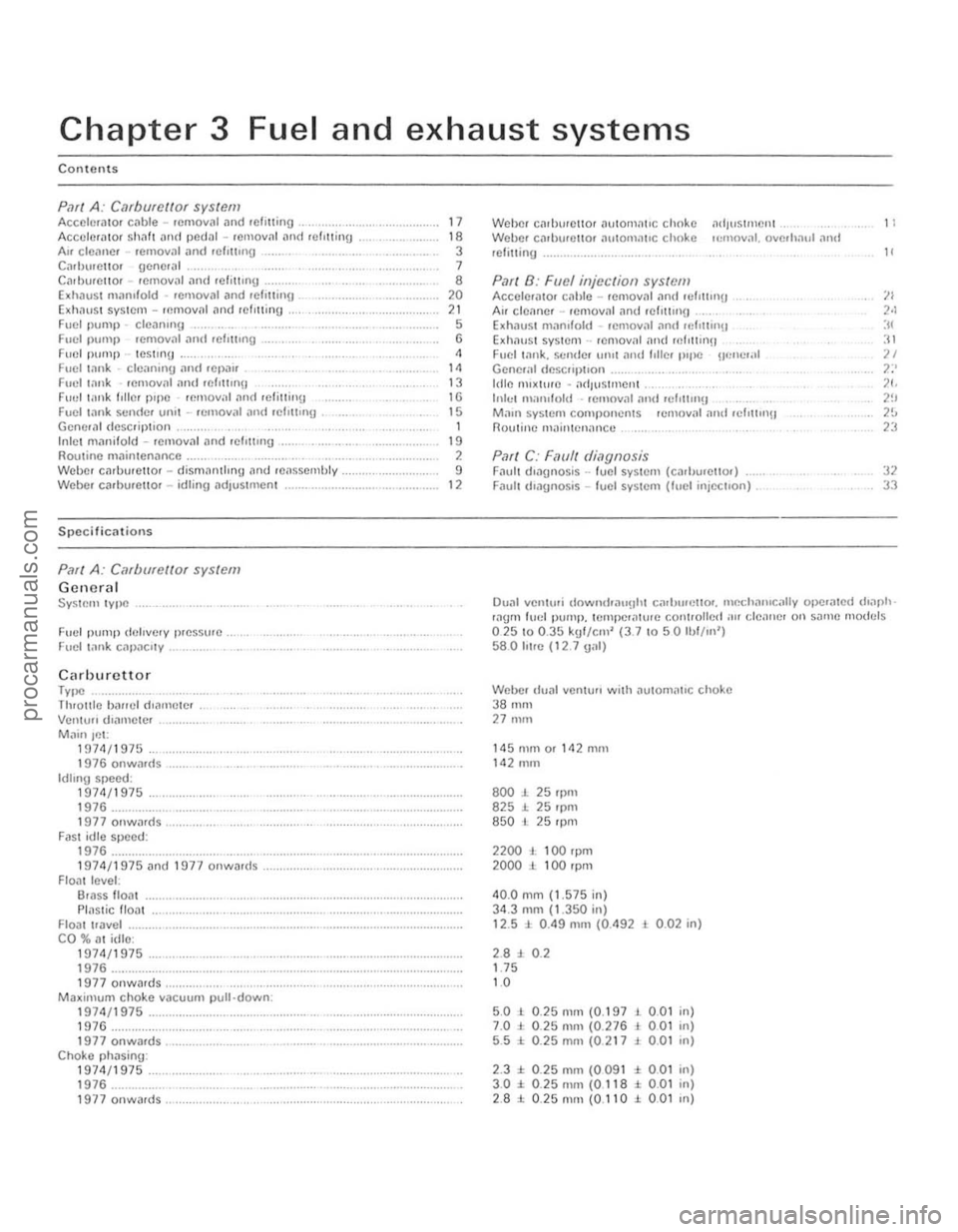
Contents
Pari A: C,UbufCIIQr system AccchmllOf cable -removal .1n( rerilling , ........... , ...... . Accclm
PMf A: Cilfborettor system
Gctwrctl System 'Y lloC
Fuel pump delivery l)reSS\lrc .
Fuc l I,ln k c,lpnc,'Y .
Cilrhurcttor lytle Tluol1le baf!el dranwtcr
Vcnlull d"ll'ICICI
Mainjct: 1 !I71\/1975 1976 onwards Idlong speed: 1971\/1975 1976 .............. .. 1977onwilfd5 FilSI idle speed: 1976 1974/1975 ilnd HI77 onwilr(ls
Floal leveL: 6111SS lIoal
PlaStic float
Floill Iravel ...
CO %
111 idle: 197<1/1975 1976 1977 oowards ......... ........ , .................... . Maximum choke vacuum p ull down. 1974/1975 .......... ....... .. 1976 1977 onwards ............... . Choke phasing: 1974/1975 1976 .......... .. 1977 onwards,
17 18 3 7 8 20 21 5 6 4 14 13
16
15
1 19 ,
9 12
Weber calburellor
Exh,luSt system .. lemoval ,1nd rnf,ttin!1 Fuel l:lnk. sCIld el utUt and follel l"floC !!fmc.,,1 Gene.;,1 descflpt,on
Irlle nuxture • ,1d/l' Slmenl ..
Inle t man,fold .• emoval and 'ef,nn,!]
Ma,n systcm compo nents .emoval and rd,ll'n!) nouline m.1jnlcn,lnce .
P.1r( C: F.1l1ff di,1gnosis Fintlt d,n!]l1osis .. fuel syslem (cadJll,ello,) Faull d'agnosis -fuel system (fuel injeCI,on) ,
11
"
:12 33
Dual vcnlu.i downcfoa"llhl carh,",cl1or. m~IHI"'Ci,lIv Or.cHnlcd (hap'" .agm luel pump. tempcrilh rrc cOllI/oiled air clenne, on sallHl "'0111:15 02510 0.35 kgl/cm' (3.7 1 0 50 1I,l/ln') 580 Il1re (I2 7 1)011)
Weber (Iunl venturi wilh autorn;rt,c choke 3801111 27 nun
1450101 or 1<12 mill 142 mm
800 J. 25 rpm 825 1. 25 'pm 850 l 25 rpm
noo ,., 100 rpm 2000 ± 100 rpm
40.0 mm (1.575 in)
3 4 .3 mm (1.350 in) 12.5 1. 0 .49 mOl (0.492 L 0 .02 in)
2.8:l. 0 .2 1.75 10
5 .0 1 0 .25 nun (0.197 7.0 J . 0 .25 mm (0.276 5.5 :t 0 .25 mill (0.217
2.3 ± 0.25 mm (0091
, 0,01 , 001 , 0.01
± 0 .01
3 .0 :t. 0 .25 nun (0 118 ± 0.01 2 .8 :l: O .25mm{0.110 J. 0 .01
in)
in)
,n)
in)
in)
III)
procarmanuals.com
Page 68 of 205

)
Chapter 3 Fuel and exhaust systems 67
Torque wrenc h setting s Fuel P\JlllP Inlet n'
G ene ra l SyS1c'" Iype Idl e sp ce d CO "o,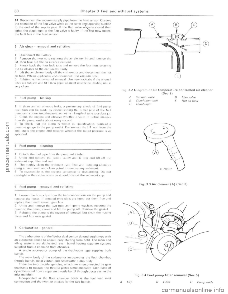
I,
68 Chapter 3 Fuel and ClChau st systems
14 Dlsco""C(:t lhl) V;1CllUlll ~lIprly IUPC (10111 th,: h<:.11 ~Cllsor Oh~r.rv'J Ihe O,) CI; ,hOil Olillc U;1,) villvi) whll!) ,'Ilhe s,.,mc hn~c ;)PpIY"l!1 SUCtIo n 10 Illu cnd 01 lhc ~"ppIV plpn It Ihe 11;111 v,llve 'C~1"'S closed then CI!lu:r tlw (i .dplu;)!l11l or 1110 flap V"IV~l IS 1 ,I\Jlly If thl) I lilP now opf;n~. Ihe f;lUII 1":$ III Ih,~ hea l ~(:n ~o(
3 Air clear -rCllloval nml le fittinu
1 Q,seol1ll(;f:l lhe 1I,,1h !IY 2 Remove tli' l two n"l~ '<:t:lII,n!l 111".111 (,"'.III,,, lid "nt! ",m""" II,,, hd. til ... " I,ll" OUI 11", "" 1.1,',,,,.., 0;1,,11\,,111 3 Kuuc.k '>.ILk lh" I"", Iud. l"hs _mel 'CIIlU"" Ihe toUl Ilul:> so'' tuH1!! lh,);oll ch',IIlt" if) !he r.;Hhu"·lw, lu>
H Ih.·", .11" .. II ""Y'"'''' 1",,1..~ " 1",·I"",,,,,,y •. h d).. .. I 1111"1 I""" P "I~",'I"'" ':,111 I" , ",.,11" I,V ot"".""" .. ,.I"I~1 110" ",,11"1 1"11" "I II ... It ... 1 1"""1' .,,'U I '.(""","'I",!) II", 11111"1' OI,lh' l I,y., I''''!III, (,I 1"1,,, I"" ~II.,~" I." :' Cr.,,,1.. 111" ""!I"'" .",,' /,h~",\"" ..... 1"·. 1"" _, "'''''1 .. 1 p,'III,1 '''''''', .... I",,,, .h" '''''''I' .",,1"1 .,11111" I''''''''y .. , .. ... ,,,' :1 To c.h""k 111.11 II,,! I''''''P ,<; w.II"" 'h ~p""oI" .'IIUIl. ,,,,,,,,,,, ,1 .' p.e"~",,, !la,,!!,! 1 0 th,! IU""p outkl D'M·,"''' ... '. t III" II r ","", hom 11", co,l. c,;ulk th" ""!)"l{, ;11111 UhM"V" wh",h'" Ih" 1>\1,1,,1 1''''';''''111 " ." SllCCd'e d
5 Fucl purlll) dc,,,,illg
D"I,'I:II (h .) 1",,11111'" 10",,, II,,· 1"""1> ,,,I ... lui", 2 Umlo ,IIlIt """("'" lh,' ( •. ".", '~" ...... _ .. "t 0 ""'1 .""t t.!1 "tt lh,· .... ~III".· .. 1 "''1'. 1,lk' '''Ht ,.",,1 :l 1 t""oU~II,ly (.1""" 11", ·,,-ltll"':I'1 "tl'. 1,110;' ,11,,1 III''''t''''\) ,.1,.11,,1,,·, U~"'H a 1);ou'tl>l,,·,11 ,tlHI ( .11"", 1";h"II() '",n<) "" "ny ",·,111"(:1'1 ,I In ,,,,,,,,,,,,,,101,- " tt", "'''''','! ""qll"IlI;" !to ,h"m.IIIIIII'H Dn " .. 1 UVI""!tl'I"" II,,, '.""1", '.,.,.,,\' .• ,; '( (",,1<1 (h~t'''1 tlon ~.,(t llw,"1 ("'t>
6 Fuel P""'tl ,emovnl ,md .uliuiny
L()U~"II II", h""l! ,.ht ... Io<)l1l Ille IWO C(Jlln," (1011:; ')" It\!! P""' P ;,,,,1 ''''"0~C Ihl! ho~" If "'''"1)<,<1 IVp" d, .. ~ ,,,e I'lh .. '<:I cu, Ih,-m Iol'(' .",d H'lti.,e.C lh"m w'lh ).C'l'W lH'" • . ht> .. 2 Undo ,lnd "'!II(We (h" [<\0 nul~ ""d ~fI"'l!1 wn"h,,,~ senor'''!! II", jllllnp to (li e 1"11"'\1 rI"'" H!ull'(11Ih' I,uml' nil nCIll()'" II", !I"~~~I 3 n(:l.tinlH lhe 1""111' 'S the '(:YI:'~ 0' '(:11101';11 . hUl de,H' lhe ,,,.,,\11\1 ',lC",S ,lIld 1'1 " r"' ..... 'I,l~kc(
7 C;orbllrnU or · gCnc'ill
'Th" c,,,hu .. ,uu< IS nllh" \Vclx.r ci .. ,,1 "CIll,,1I (lownd';1uuhl lVI)C Willi ;111 .1II1UI\1;.U<: ('ho~ (~ 10 (:nsur" C;1Sy S.,\lIII1\1 100'" cold The m,un ;Ultl
IItim U sy~",,,,s ;IIe dup"t;~ I1 ... '(I. p;,ch b.1 .. cl h<1Y1I\9 S('j).lf<11e SVS1(:II1S supplied Irom 11 (;0"'111011 110<11 ch,lI1'u." A S'"(JtC ,'lcd':f<110' pump 01 Ih~ dJi)ph"lYIll lVt)C supphes hOlh b;lr!
3 2 O,; ,ur;om 0 1 nir tcmpcr;ohorc contro llC d ilir clcnn.] r (Suc 2) V.I<: IIII11! /",.1,·
f)""d".IfltJJ lllUl f),.II""_"''''
(A j
()
1 1"1:'1' V;,'~!! I/ul ;'" /I"IV
FiU . 3.3 Air c lcm'er (A) (Sec 3)
(c ' ..
Fig_ 3.4 Fuel pump filter rcmo",,1 (Scc 5)
8 c Pump body
procarmanuals.com
Page 70 of 205
)
-
Clwpter 3 Fuel
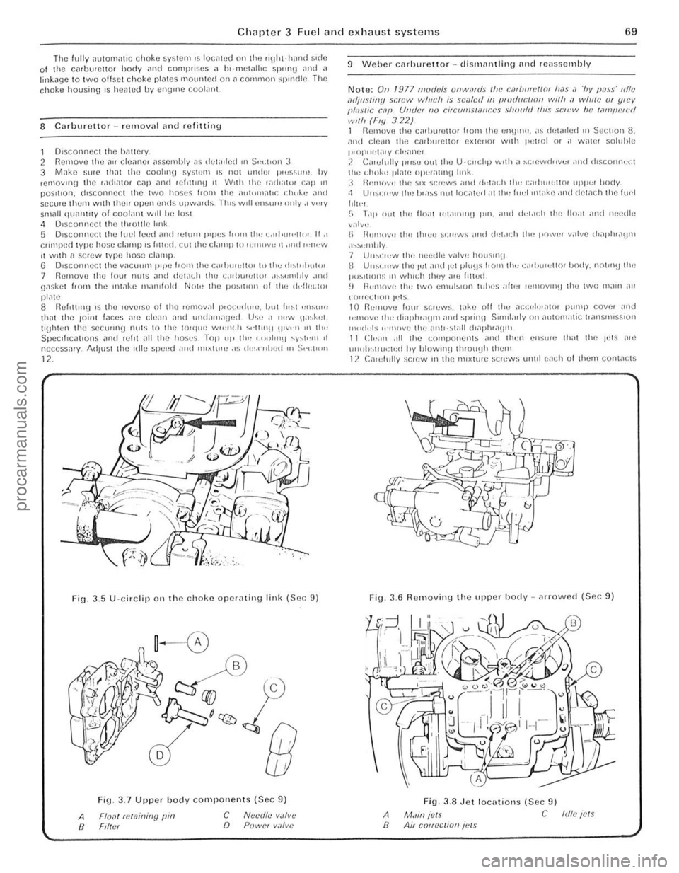
Fig. 3,5 U·circlip 011 the choke operatil\g link (Sec: 9)
A /I
Fi9 3_7 Upper body components (Sec 9)
Flo,lI telaininy pm Ftll.'t c o NlJcdto V;I/V(!
POWCI v.1lvc
9 Weber Cilrhurettor -dismilntlinu [lnd reas~ernhly
Note: On 1977 mod(!/s onw,lf(II /lIP. cmlll/id/ot 11,15 ,1 '/Jy PilIS' tdle IIdIItS/IIIY SP~'W willch IS sc,l/r:iI //I l!lodl/cllOn wl/h <1 willie (}f ljlCY 1,/,'sIIC (:,11' UlI(ler /10 CItC(ff!!s/a/lces should {/II.~ SCI('"W h e /,)t!J/JlNl'd wi/h (Fly 322) 1 R(!II1Ov(! the C.1,h"n;llor I! O"l th e ':Ol!)""' . ,1~ dr;w,lp.oI ,n Section 8. an d cl(!,lIl th.) f:ilrl""etlor extC"Of w'lh 1'.,['01 or a walt' soluhle t"OI",,:l;\,y 1'/,,;)11(:1 J. C;, rdully I"'S" 0,,1 Ihe U'CIIClrp w,th a hC,(lWII"v" •• lIul ,h~COIUlo:cl til" '.ilok" pl"w oj)l:(allnulrnk :I 1\""10\"" tire ~I X ·,,:,,'ws ;'"It ,i,-(;" .h II" , GIl1"""llor "Ill"" body. ·1 Uns';",w llr,) h'n~s nul locnl"d:ot th" ((",I ,nwk,) .'nd d el.1cll Ihe flU'l
Iolt"1 (; T"II Ollt tlo" lIo;i! ,,,t.1"lII'!J pm. ;,nd dd.1{,1r II,,) 110;11 ,Hl d needh~
v:otv" I, R"",,,v,, tlon th,c" ~c,,:ws and d"t.u:1r tlw po","", valvc d';lpl"a!)1ll .'~h,,"'tJly 7 U"hl:",W thn ncedle ~"Iv" ho,,~,nu 8 U"suo:w the It)( and Io:t pt"\Js I. o r" til" c."jJ\""l1m Imdy. not"l\) th .. , p"~.'I'o"s III wh",h 11,,;y ;0,(, f'lll:d ~) I~l"ll()v" (h" two cn ,"b,on luhes ;011'" ,,,'IIOVIII\) the two lll,lIn "" l"II rt<.:t,on t,;ts 10 1l<:!lIUVC lorn sr.'l:ws. t;JkC nil II", ,1co:"I,;r.lto , j)"Il'P co"", ,,,,d ,,,,,,,-.vOl ttl<, d',Ij,lua!l1l> ;Hld 5P(in'l SUlul,,
Fi\j. 3.6 Removing the upper h ody -nrrowed (Sec 9)
A II
Fig. 3,8 Jet locatiolls (Sec 9)
Mwn ICIS C Idlc ICIS Air COtt~'CIIOIl ;"IS
procarmanuals.com
Page 71 of 205
70 Chapter 3 Fucl and exhaust systems
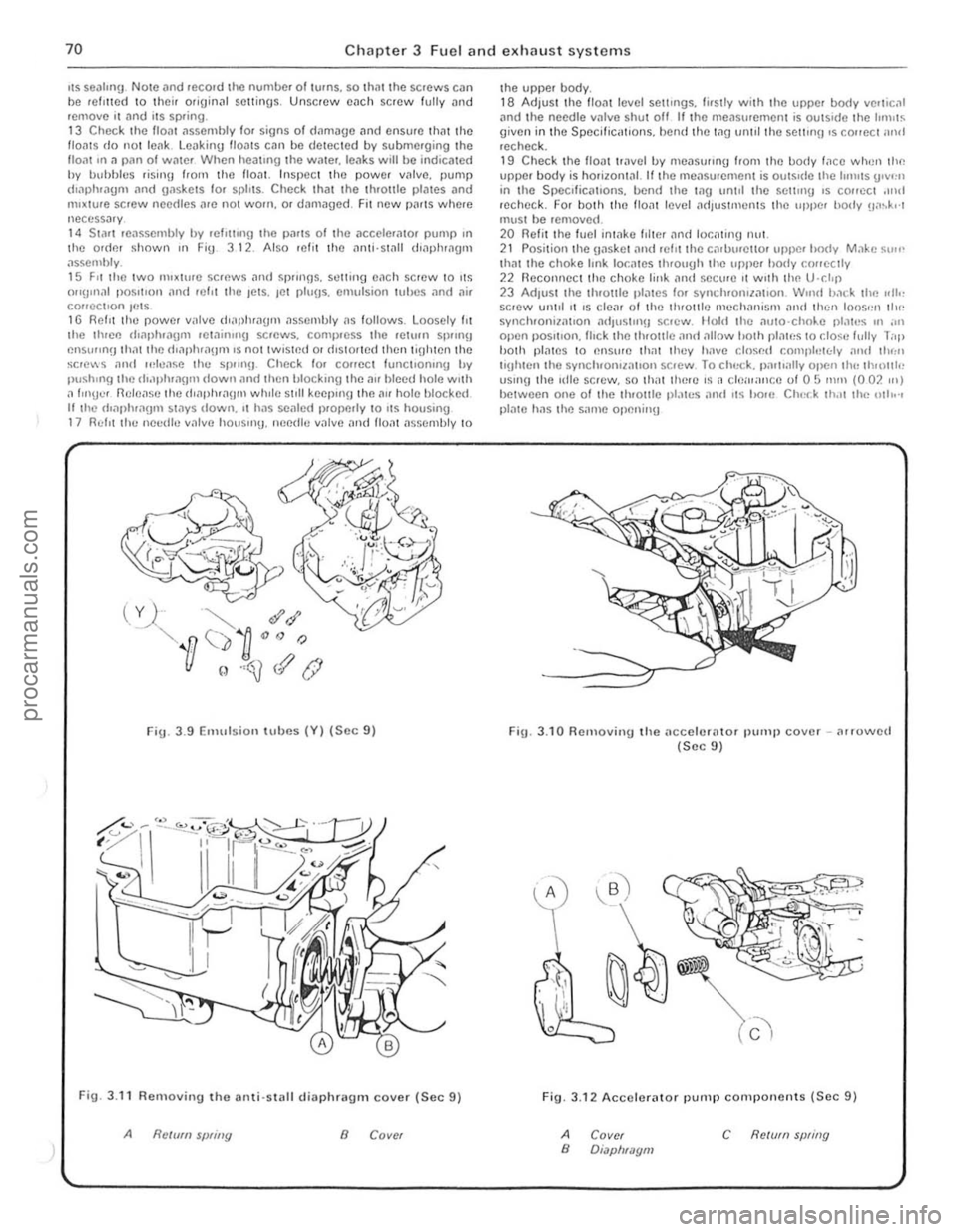
liS seatmu Note ,1nd reco.d the number of lurns, so th,11 the screws can be relltted 10 their orjuin~' settings . Unscrew cilch screw fully and remove it and its SPfing . 13 Che<:k the lIoat
Fig. 3 .9 Emulsion t u bes (V) (Sec 9)
Fig, 3.11 Removin!J tho IIlIli'Slilll dillphragm cover (Soc 9)
Refum sWing 8 Cover
the upper body. 18 Adjuslthe flo." level settings, fi,slly w;l h the upper body verlical .md I he needle villve s hut off lithe meilsurerneot is outsIde Ihe IInlllS given in the SpecifiC
Fig. 3.10 Relllovingllie IIccelcrillor pump cover -(lrrowcd (Sec 9)
..
Fig. 3.12 Accelerator pump components (Sec 9)
A B Covcr Diapl/mom c RC/(lfll swing
procarmanuals.com
Page 72 of 205

) Chapter 3 Fuel and exhaust systems
FiU _ 3.13 Components to he checked (Sec 9)
A
8
C/u':(:A fur wP.olf alJd (/illlli'f/I.l Clwck '(If .~/I"lIitJfJ
C CI)(xk for hd,ill{J {) Check (Of spfrlling
10 Weller cnrhurettor ""tom,lIie choke - rcmov,]L overhaul
and refitlinu
1 DlsconlH!~1 Ihe i)illicry nC\j
le"sselllhly. 11 Ik"ssemhle the choke meCh'1I11SI11. 12 Relit ll1e v"CUUIll til"phl1'lI)lIl alld hOUSII1,). enslllinu th"t lhe (hilphl,l()fIl IS lIolt before lile housing IS fllted. 13 Ensure thm the O-IIllg is correctly locmed in the choke housinU then reCOllnect the lower choke I",k Position the assembly and secure il WIth the thr ee sClews . ensure thnt the upper choke link loc"tes
cOlrectly tluouUh the c"rlJlJretlOf body 111 RecOllllec t the upper choke Imk to the choke Sp"l(tie. 15 Check the V"CUUIll pull· down
Note: lile pfOccc/
.l.I. .... , •• ,. ••. • .. .• . ,,~ ......... , •• , •• .;..,.: .•• ' •.•••• 1 . ;."
.,.', .,1,,/. 1,,' .. 1 . .. . , 1.,.: .. 1,.1.1,.1 .•. : ...
J
Fig. 3.1 4 F loat level adjustment t
.------
./ /' (
Fig.
/
3 .16 Automatic c hoke h ousing alignment (Sec 10)
A Rich c B Normal scl/lllg
marks
71
procarmanuals.com
Page 73 of 205
72 Chapter 3 Fuel and exhaust systems
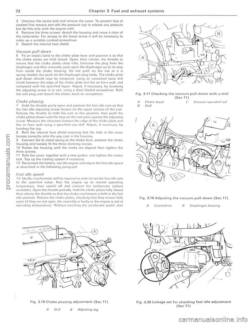
3 Unsc.cw the cenlle bolt and .emovc the cove •. T o p
locmes COrfeclly 01110 Ihe t :le\] C
Filsl idlv speL'd 1 3 hlc;IlIy" tachomcte. wlIII,c .eq,,"ed !lllmlc. 10 sellhu t,'~1111l1! 'P'" 10 lhe ~peclllncl v.1Iuc . nUll lhc CnnUlc lip to no.,,,al opc.at"I!1 t,:'Upe."lu,e. then ~wO\ch oil ;Jml COllllect Ihn tachomete. (whe.e .wn"a"h,) OpCl1t he Iluollie pal\lally. hnhllhc chokc pl.1\(.)5 lully closed tI'"" 'ele,lse tht.! th,ollie $0 Ih.111he cho~e 1""ch.1111$I11 IS held 'n the fast "II" fK151\10" Relc"$c the cho~1"l pl.ltCS . d" . .:ckllll! lh;lllhcy .cmaln lully olwn (II they ".c not open. Ihe ,lsse rnlJly IS I"ully 01 Ihe cnU"lc ' S 1101 al 01Ie .,11111IJ len'I/C,,'lurc) Wlthoul louchl"H the ;lc c"le."to. ved"I. Sliltl
, ,
~A
Fig. 3.1 9 Choke phasing adjuSlme'lI (Sec 11)
A 0,,/1 8 AUjus/my'"y
Fig. 3 .17 Checking the Vllc .. "m pull·down with l' drill {Scc 111
A t:lils/lc Im",' C V;//:1I11111 ('I'~'f,~lmllull B DIJII
Fig. 3.18 AdjtlslinU the vacullm pull- down (Sec 11)
A 8
Fig. 3 .20 linkage SCI fo r checking fast idle adjustment (Secl1)
procarmanuals.com
Page 74 of 205
Chapter 3 Fuel and exhaust systems 73
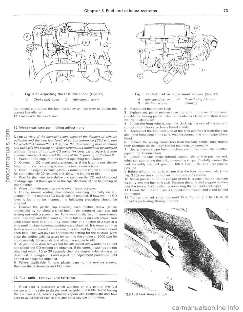
Fig 3.21 Adjusting the fast idle speed (Sec 11)
A Clloke f(llly Olwn ()
the 1:1l!)1I1" alld ;HI)"~;1 lhe lasl ,die s<:rew as llecess;uy 10 ohlain lhe COlleCI la~l I(llf~ 'Ilill 11 Finally felll lhe ,\(I cif,.1ne,.
1 2 Weber carburettor ~ id lilllJ ndjustment
N ote: III view of lfoe illcfem;illg ,1WmeIJeSS ollile d,lI/flefS of exh.lflsl pol/ulioll olml Ihe vefY low levels of cmbol! //Ionuxirle (CO) emission fOI which Ihis e,,,burel/o, is dcsiW!N/. IIIe: slow fUnlling mix/ute: se:l/ill9 ,wd tin' b,lsie idle svlling all WCbt'f e,ltborcl/OfS shoufllllu/lw "djus/cd Wililoll! OW (ISO of a {!fop!"!, CO flfv/ef (c·Xll,lOS! fI"s iflf'lfyser). Bdum CUfluHencillY work ,1150 f(;o1(/ /he flO/t' .11 til<: IW9innilly of Sl'CltOn 9 1 Walm LIp lh(l (ll1gU)(l 10 ilS nounal operalinu If:l1lpCrailH(l 2 COlIIlCCl .1 CO nleler ilnd " lolchol1l(llel. ,I lhe Iilller ,s nOl aire
IUSlrnent of lho mixture (CO levol) w,lIb(l requll(ld. It howevel the CO levcl is lound to be II1COHCCt thc 10110willII p locedwe should be ,ulnp!Cd 7 Rcmove lhe plast,c C
corr(lCl readings me ohwined. 9 Whe,e applicable f it new plas tic cnps 10 the mixture sc,ews. Remove th(l taChOmeler .1nd CO meter.
)13 Fuel tilnk ~ removill .lIld re fittin g
Gn;at c
2 O,sr.onnuct tho !Jallf)ry I,·"ds
c S,.',l/,·" /J/IIY rd,) ,wI lemow.')
3 Syphon o1"y petlOl Ii,,,,a"u!)!) III Ihl"! t,lnk min a 1",,1<11 conwu'"r sUlt
~.* ..... ·0 ~'.~',":L: :~ .. ~" :".~ r~r· .. '.~ . . ' . -
.... ', . ~ , . .
iil~);-< .~:a
1 3 .8 F uel tank StrllP lInd 1!OIt
procarmanuals.com