1973 CHEVROLET MONTE CARLO length
[x] Cancel search: lengthPage 8 of 86
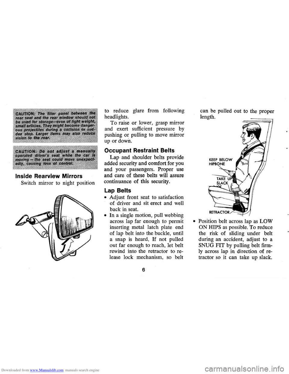
Downloaded from www.Manualslib.com manuals search engine Inside Rearview Mirrors
Switch mirror to night position to
reduce glare from following
headlights.
To raise or lower, grasp mirror
and exert sufficient pressure by
pushing
or pulling to move mirror
up
or down.
Occupant Restraint Belts
Lap and shoulder belts provide
added security and comfort for you
and your passengers.
Proper use
and care of these belts
will assure
continuance of this security.
lap Belts
• Adjust front seat to satisfaction
of driver and sit erect and well
back in seat.
• In a single motion, pull webbing
across lap far enough to permit
inserting metal latch plate end
of lap belt into the buckle, until
a snap
is heard. If not pulled
out far enough to reach, let belt
rewind into the retractor to re
lease lock mechanism ,
so belt
6
can be pulled out to the proper
length.
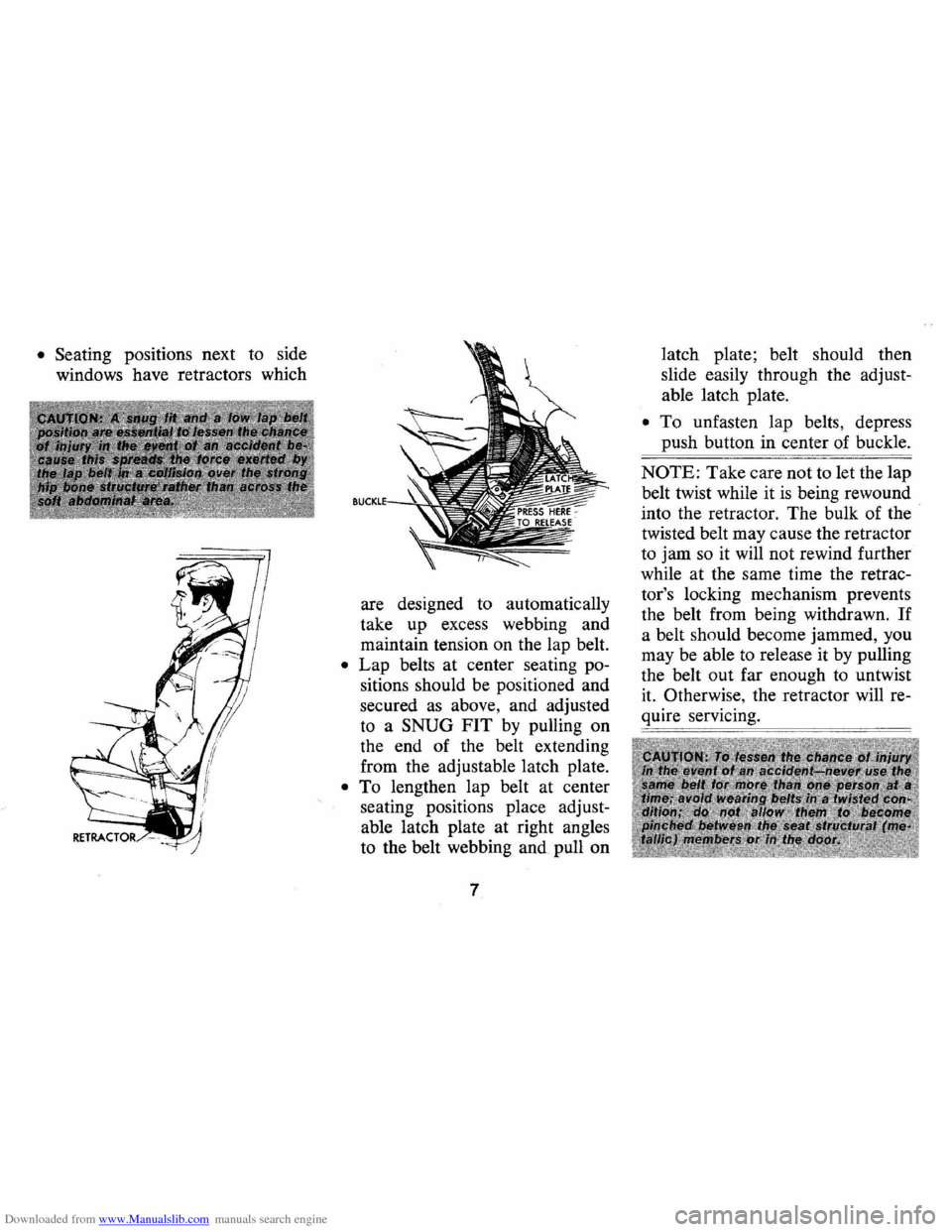
• Position belt across lap as LOW
ON HIPS
as possible. To reduce
the risk of sliding under belt
during an accident, adjust to a
SNUG FIT by pulling belt firm
ly across lap in direction of re
tractor
so it can take up slack.
Page 9 of 86
Downloaded from www.Manualslib.com manuals search engine • Seating positions next to side
windows have retractors which
are designed to automatically
take up excess webbing and
maintain tension on the lap belt.
• Lap belts at center seating po
sitions should be positioned and
secured as above, and adjusted
to a SNUG FIT by pulling on
the end of the belt extending
from the adjustable latch plate.
• To lengthen lap belt at center
seating positions place adjust
able latch plate at right angles
to the belt webbing and pull on
7 latch
plate; belt should then
slide easily through the adjust
able latch plate.
• To unfasten lap belts, depress
push button in center of buckle.
NOTE: Take care not to let the lap
belt twist while it
is being rewound
into the retractor. The bulk of the
twisted belt may cause the retractor
to jam so it will not rewind further
while at the same time the retrac
tor's locking mechanism prevents
the belt from being withdrawn.
If
a belt should become jammed, you
may be able to release it by pulling
the belt out far enough to untwist
it. Otherwise, the retractor will re
quire servicing.
Page 11 of 86
Downloaded from www.Manualslib.com manuals search engine • To fasten the shoulder belt, un
stow it and place the knob on
the shoulder belt end in the
keyhole on the lap belt latch
plate. (The latch
is designed so
that this attachment can only be
completed before fastening the
lap belt.) Tilt the knob as neces
sary, to pass
it through the slot.
Pull the knob firmly upward to
seat it at the narrow end of the
keyhole, then fasten the lap belt.
• Shoulder belts are lengthened
and shortened in the same man
ner
as center seat lap belts.
• Shoulder belt should have suf
ficient slack to insert a fist's
width between your chest and
the belt. This can be checked
by inserting a clenched
fist be
tween the belt and your chest
with thumb against chest and
back of hand facing upward.
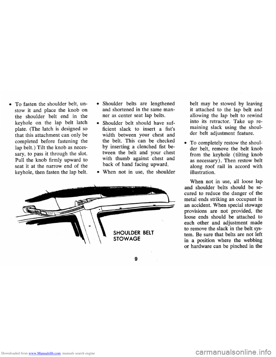
• When not in use, the shoulder
SHOULDER BELT
STOWAGE
9
belt may be stowed by leaving
it attached to the lap belt and
allowing the lap belt to rewind
into its retractor.
Take up re
maining slack using the shoul
der belt adjustment feature.
• .To completely restow the shoul
der belt, remove the belt knob
from the keyhole (tilting knob
as necessary). Then restow belt
along roof rail in accord with
illustration.
When not in use, all loose lap
and shoulder belts should be se
cured to reduce the danger of the
metal ends striking an occupant in
an accident. When special stowage
provisions are not provided, the
loose ends should be attached to
each other and adjustment made
to remove the slack in the belt sys
tem. Be sure that belts are not left
in a position where the webbing
or hardware can be pinched in the
Page 61 of 86
Downloaded from www.Manualslib.com manuals search engine 3. If radiator is not equipped
with a drain valve start to
drain system
as follows:
a. With engine stopped , insert
one end of a 5-foot length
of
% inch tubing into the
filler neck until it touches
the bottom of the radiator.
b. Insert any type of large
syringe into the open end
of the tubing and initiate
the siphoning process by
squeezing and releasing the
ball.
c. Completely drain radiator
coolant through the siphon
tube. (To speed this
oper
ation, the drain plugs in
block can also be removed.)
d. Remove tubing (install
block drain plugs,
if re
moved) and add sufficient
water to
fill system.
4. Close drain valve (install
block drain plugs,
if removed)
if so equipped and add
suffi
cient water to fill system.
5 . Run engine, drain and refill
the system,
as described in
steps
1, 2, 3, and 4, a suffi
cient number of times until
the drained liquid
is nearly
colorless.
6. Allow system to drain com
pletely and then close radia
tor drain valve tightly if so
equipped (Install block drain
plugs,
if removed.)
7. Remove recovery cap leaving
hoses in place. Remove
cool
ant recovery tank and empty
of fluid. Plush tank with clean
water, drain and reinstall.
8. Add sufficient ethylene glycol
coolant, meeting GM
specifi
cation 1899-M, to provide the
required freezing and corro-
59
sion protection-at least a 44
percent solution
(_200P). Pill
radiator to the base of the
radiator filler neck and add
sufficient coolant to the
re
covery tank to raise level to
the
"PULL HOT" mark. Re
install recovery tank cap.
9. Run engine, with radiator cap
removed, until normal
operat
ing temperature is reached.
(Radiator upper hose becomes
hot.)
10. With engine idling, add cool
ant until level reaches bottom
of filler neck and install
radi
ator cap making certain ar
rows line up with overflow
tube.
It is the owner's responsibility
to keep the freeze protection at a
level commensurate with the
tem
peratures which may occur in the
area of vehicle operation.
Page 74 of 86
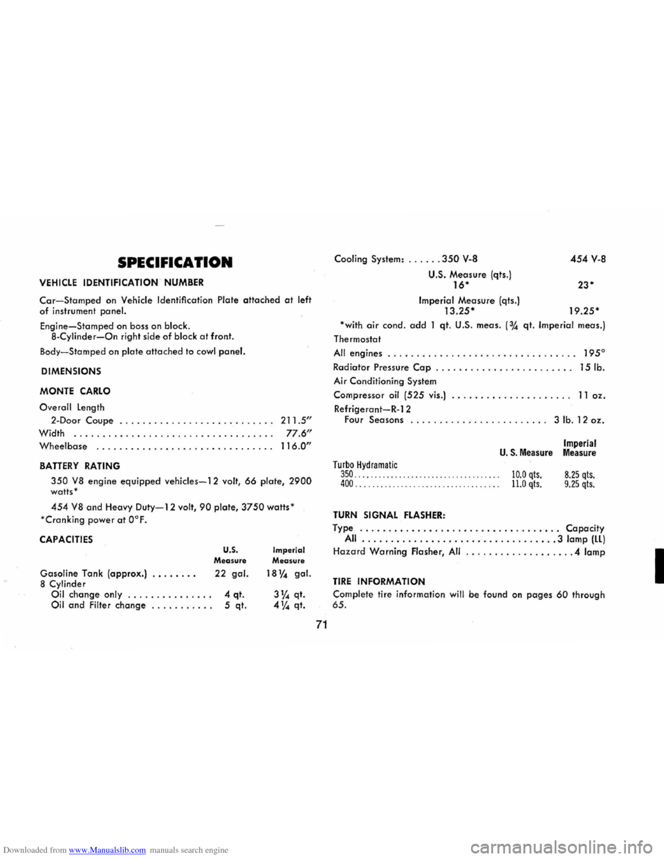
Downloaded from www.Manualslib.com manuals search engine SPECIFICATION
VEHICLE IDENTIFICATION NUMBER
Car-Stamped on Vehicle Identification Plate attached at left of instrument panel.
Engine-Stamped on boss on block .
8 -Cylinder-On right side of block at front.
Body-S tamped o n plate attached to cowl panel.
DIMENSIONS
MONTE
CARLO
O ve rall length
2-Door Coupe ...
.. . . . . . . . . . . . . . . . . . . . . . . 211.5"
Width ... ......... ......... ............ . . 77.6"
Wheelbase ............................... 116.0"
BATTERY RATING
350 VB engine equipped vehicles-12 volt, 66 plate, 2900 watts '
454 VB and Heavy Duty-12 volt, 90 plate, 3750 watts'
' Cranking
powe r at O°F.
CAPACITIES
Gasoline Tank (approx.) ....... . B Cylinder
Oil change only ... ... .... .... . Oil and Filter change .......... .
U.S. Measure
22 gal.
4 qt. 5 qt.
Imperial Measure
18% gal.
3% qt. 4% qt.
71
Cooling System: ...... 350 v-a
u.s. Measure (qts.) 16*
Imperial Measure (qts.) 13.25*
454 v-a
23*
19.25*
'with air cond o add 1 qt. U.S. meas. (% qt. Imperial meas.)
Thermostat
All engines . . . . . . . . . . . . . . . . . . . . . . . . . . . . . . . .. 195°
Radiator Pressure Cap . . . . . . . . . . . . . . . . . . . . . . .. 15 lb.
Air Condit ioning System
Compressor oil (525 vis .) .............. ... .... 11 oz.
Refrigerant-R-12 Four Seasons ........................ 3 lb. 12 oz.
Turbo Hydramatic 350 ........... .......... .. ... ........ . . 400 .. ................... .. ... .... .. .. .
TURN SIGNAL FLASHER:
Imperial U. S. Measure Measure
10.0 qts. 11.0 qts. 8.25 qts. 9.25 qts.
Type ................................... Capacity All ..... ..... ........................ 3 lamp (ll)
Hazard Warning Flasher, All .. , ............... . 4 lamp
TIRE INFORMATION
Complete
tire information will be found on pages 60 through 65.
I