1969 FORD MUSTANG oil pressure
[x] Cancel search: oil pressurePage 342 of 413
07-03-02
FMX Transmission
07-03-02
COMPONENT INDEX
OIL PAN
Assembly
Removal and Installation
OUTPUT SHAFT
Assembly
Inspection
OUTPUT SHAFT BUSHING
Disassembly and Overhaul
PARKING PAWL
Removal and Installation
PRESSURE REGULATOR
Assembly
Disassembly and Overhaul
Inspection
Removal and Installation
PRIMARY SUN GEAR SHAFT
Disassembly and Overhaul
Inspection
REAR BRAKE DRUM SUPPORT BUSHING
Disassembly and Overhaul
REAR CLUTCH
Assembly
Disassembly and Overhaul
Inspection
Page
03-29
03-11
03-26
01-11
03-17
03-13
03-28
03-21
01-16
03-12
03-18
01-11
03-17
03-26
03-18
01-15
REAR SERVO
Assembly
Disassembly and Overhaul
Inspection
Removal and Installation
REAR SUPPORT
Assembly
Inspection
REAR SUPPORT BUSHING
Disassembly and Overhaul
SELECTOR LEVER-CONSOLE SHIFT
Removal and Installation
THROTTLE LINKAGE
Adjustment
Parts Repair or Replacement
TRANSMISSION (Complete)
Removal and Installation
TRANSMISSION CASE BUSHING
Parts Repair or Replacement
TRANSMISSION CASE LINKAGE
Parts Repair or Replacement
VACUUM DIAPHRAGM UNIT
Assembly
Adjustment
Checking
Page
03-28
03-24
01-16
03-12
03-28
03-15
03-21
03-08
03-05
03-05
03-14
03-26
03-25
03-29
01-07
01-04
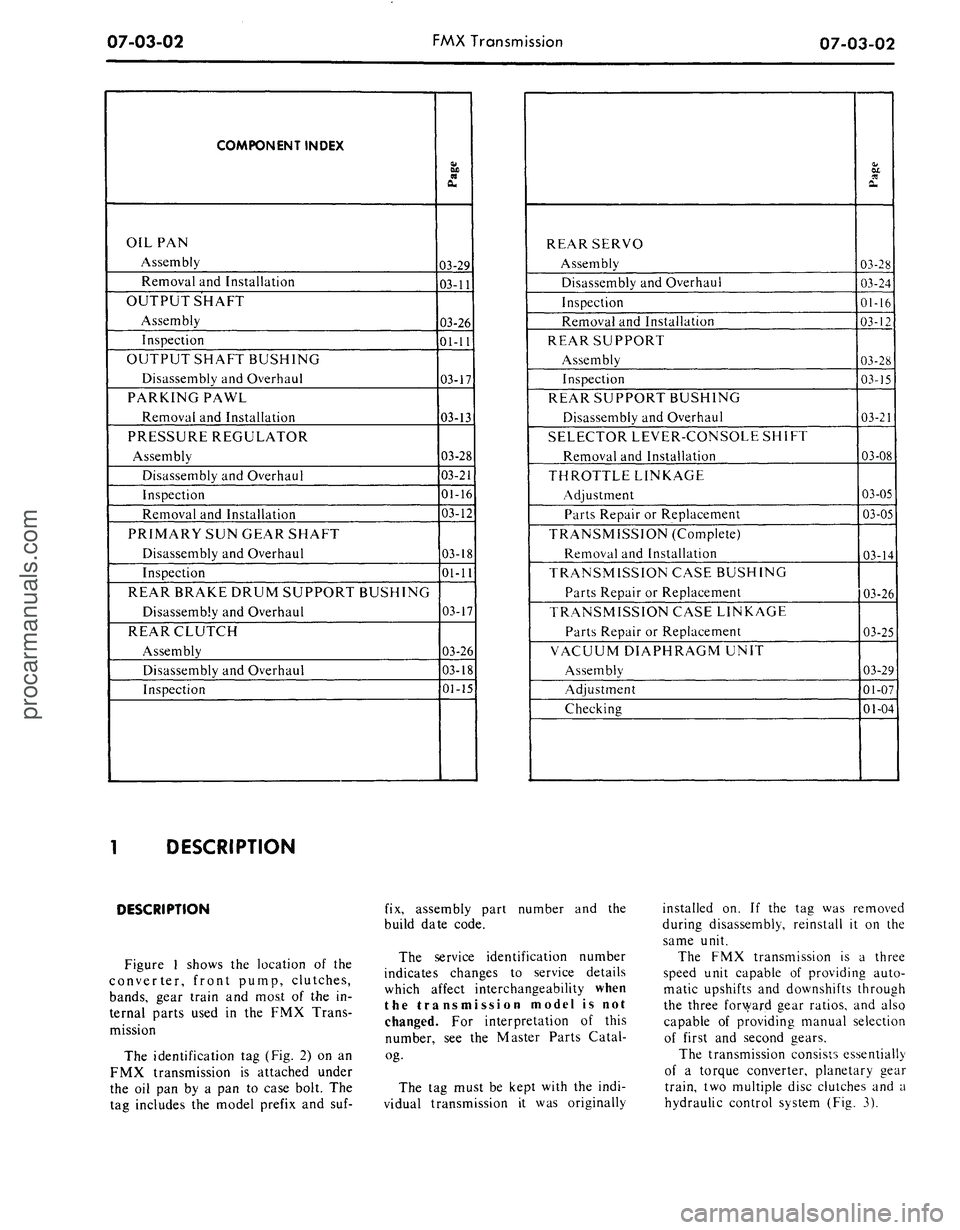
DESCRIPTION
DESCRIPTION
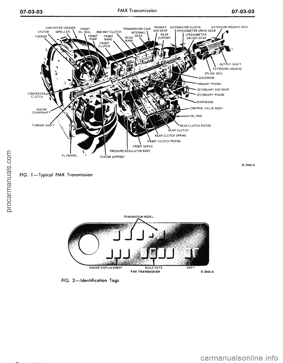
Figure 1 shows the location of the
converter, front pump, clutches,
bands,
gear train and most of the in-
ternal parts used in the FMX Trans-
mission
The identification tag (Fig. 2) on an
FMX transmission is attached under
the oil pan by a pan to case bolt. The
tag includes the model prefix and suf-
fix, assembly part number and the
build date code.
The service identification number
indicates changes to service details
which affect interchangeability when
the transmission model is not
changed. For interpretation of this
number, see the Master Parts Catal-
og-
The tag must be kept with the indi-
vidual transmission it was originally
installed on. If the tag was removed
during disassembly, reinstall it on the
same unit.
The FMX transmission is a three
speed unit capable of providing auto-
matic upshifts and downshifts through
the three forward gear ratios, and also
capable of providing manual selection
of first and second gears.
The transmission consists essentially
of a torque converter, planetary gear
train, two multiple disc clutches and a
hydraulic control system (Fig. 3).
procarmanuals.com
Page 343 of 413
07-03-03
FMX Transmission
0703-03
PRIMARY DISTRIBUTOR SLEEVE EXTENSION HOUSING SEAL
SUN GEAR ! SPEEDOMETER DRIVE GEAR /
OIL SEAL ONE-WAY CLUTCH
FRONT FRONT
PUMP BAND
FRONT
CLUTCH
OUTPUT SHAFT
EXTENSION HOUSING
SPLINE SEAL
GOVERNOR
PRIMARY PINION
SECONDARY SUN GEAR
SECONDARY PINION
DIAPHRAGM
CONTROL VALVE BODY
OIL PAN
TURBINE SHAFT
FLYWHEEL
'REAR CLUTCH PISTON
REAR CLUTCH
REAR CLUTCH SPRING
FRONT CLUTCH PISTON
FRONT SERVO
PRESSURE REGULATOR BODY
STATOR SUPPORT
D 2045-A
FIG. 7—Typical FMX Transmission
TRANSMISSION MODEL
ENGINE DISPLACEMENT
BUILD DATE
FMX TRANSMISSION
SHIFT
D 2046-A
FIG. 2—Identification Tagsprocarmanuals.com
Page 344 of 413

07-03-04
FMX Transmission
07-03-04
FORWARD
CLUTCH
REVERSE-HIGH
CLUTCH
' INTERMEDIATE SERVO
3-2 KICKDOWN
CONTROL VALVE
RELEASE
APPLY
LOW REVERSE
SERVO
ORIFICE
LOW SERVO
LOCKOUT
VALVE
2-3 SHIFT VALVE
AND THROTTLE
REDUCING VALVE
1-2 SHIFT
ACCUMULATOR
VALVE
CHECK BALL
USED IN PHD
MODEL
TRANSMISSIONS
ONLY
LOW SERVO
MODULATOR
VALVE
GOVERNOR
CONTROL PRESSURE
REGULATOR VALVE
FRONT PUMP
THROTTLE
BOOST VALVE
OIL
SCREEN
CONVERTER
CONVERTER
PRESSURE
REGULATOR
VALVE
THROTTLE
BOOST VALVE
POLICE
AND
TAXI,
ONLY
COOLER RETURN
OIL CHECK
VALVE
REAR
LUBE
OIL
COOLER
X EXHAUST
D 2047-A
FIG.
3—Hydraulic
Control System—FMX Transmissionprocarmanuals.com
Page 351 of 413

07-03-11
FMX Transmission
07
03-11
GOVERNOR
COMPENSATOR
PRESSURE TUBE
MAIN CONTROL
VALVE TUBE
COUNTERWEIGHT
D 1815-A
FIG. 16—Governor Installed
ber to remove all weight from the
housing.
10.
Loosen the parking brake cable
adjustment nut enough to disconnect
the cables from the equalizer.
11.
Remove the extension housing
attaching bolts. Slide the housing off
the output shaft and remove the gas-
ket. When removing
the
extension
housing and/or governor, hold
the
output shaft
and
rear support from
moving rearward
to
prevent
the
needle
bearing
and
race from dropping
out of
location.
12.
Remove the governor to coun-
terweight attaching screws. Lift the
governor from the counterweight (Fig.
16).
13.
Lubricate the governor valve
parts with clean transmission fluid.
Make certain that
the
valve moves
freely
in the
valve body bore.
14.
Position the governor valve
body on the counterweight with the
cover facing toward the front of the
vehicle. Install and tighten the two at-
taching screws to the specified torque.
15.
Position a new extension hous-
ing gasket on the rear of the transmis-
sion case.
16.
Slide the extension housing into
place and secure it to the transmission
case with the attaching bolts. Torque
the bolts to specification. With the ex-
tension housing installed, rotate
the
output shaft.
The
shaft must rotate
freely
by
hand.
If the
shaft
is
tight
or
bound
up, it is
likely that
the
needle
bearing
and
race have dropped
out of
location,
in
which case,
the
transmis-
sion must
be
partially disassembled
and
the
bearing
and
race repositioned.
17.
Connect the speedometer cable
to the extension housing.
18.
Raise the transmission high
enough with a jack to position the en-
FRONT SERVO
FLUID TUBES
PRESSURE
REGULATOR
D 1817-A
FIG. 17—Typical Hydraulic Control System
gine rear support on the crossmember.
Secure the support to the crossmem-
ber with attaching bolt.
19.
Lower the transmission and re-
move the jack. Secure the extension
housing to the rear support with the
two attaching bolts.
20.
Connect the parking brake
cables to the equalizer and adjust the
cables as required.
21.
Install the driveshaft.
22.
Fill the transmission to the cor-
rect level with the specified fluid.
OIL
PAN AND
CONTROL
VALVE BODY REPLACEMENT
1. Raise the vehicle so that the
transmission fluid pan is accessible.
2.
Drain the fluid from the trans-
mission by loosening the pan attach-
ing bolts starting at the rear of the
pan and working toward the front.
When most of the fluid has drained
from the pan, remove the remainder
of the attaching bolts. Remove the
pan and gasket. Discard the gasket. If
the same fluid is to be used again in
the transmission, filter the fluid
through a 100-mesh screen before in-
stalling it in the transmission. Re-use
the fluid only if it is in good condi-
tion.
3.
Disconnect the hose from the
vacuum diaphragm unit. Remove the
diaphragm unit using tool FCO-24.
Do
not use any
tools
on the dia-
phragm housing, such
as
pliers, pipe
wrenches,
etc. Do not
allow solvents
to enter
the
diaphragm unit. Remove
the push rod. Remove the fluid screen
retaining clip and the screen.
4.
Remove the fluid filter retaining
clip and the filter.
5.
Remove the two tubes which
connect to the pressure regulator and
the control valve body (Fig. 17).
6. Loosen the front servo attaching
bolts three turns.
7.
Remove the three control valve
body attaching bolts, and lower the
valve body while pulling it off the
front servo tubes. Be carefull not to
damage
the
valve body
or the
tubes.
8.
Before installing the control
valve body, check for a bent manual
valve by rolling it on a flat surface.
9. Install the control valve body by
aligning the front servo tubes with the
holes in the valve body. Shift the man-
ual lever to the 1 detent, and place the
inner downshift lever between the
downshift lever stop and the downshift
valve.
The
manual valve must engage
the actuating
pin in the
manual detent
lever.
10.
Install but do not tighten, the
control valve body attaching bolts.procarmanuals.com
Page 352 of 413
07-03-12
FMX Transmission
07-03-12
11.
Move the control valve body
toward the center of the case until the
clearance is less than 0.050 inch, be-
tween the manual valve and the act-
uating pin on the manual detent lever.
12.
Torque the attaching bolts to
specification. Be sure that the rear
fluid filter retaining clip is installed
under the valve body bolt as shown in
Figure 17.
13.
Install the tubes to the pressure
regulator and the control valve body.
14.
Turn the manual valve one full
turn in each manual lever detent posi-
tion. If the manual valve binds against
the actuating pin in any detent posi-
tion, loosen the valve body attaching
bolts and move the body away from
the center of the case. Move the valve
body only enough to relieve the bind-
ing. Torque the attaching bolts and
recheck the manual valve for binding.
15.
Position the push rod in the
bore of the vacuum diaphragm unit.
Using the diaphragm unit as a guide,
insert the push rod into the threaded
opening of the case. Torque the dia-
phragm unit to specification. Connect
the vacuum hose.
16.
Torque the front servo attach-
ing bolts to specification.
17.
Adjust the front band. If the
unit is a model PHB-C, D, E, F, G or
H, adjust the rear band at this time.
18.
Install the fluid filter and the
filter retaining clip.
19.
Position a new fluid pan gasket
on the bottom of the transmission
case,
and install the pan. Torque the
pan screws to specification.
20.
Adjust the rear band on
PHB-A and PHD models.
21.
Fill the transmission with fluid.
If
the
fluid that
was
drained from
the
transmission
is to be
used
again,
filter
the fluid through
a
100-mesh screen
as
it
is
poured back into
the
transmis-
sion.
Re-use
the
fluid only
if it is in
good
condition.
22.
If the control valve body was
replaced, adjust the transmission con-
trol linkage.
PRESSURE REGULATOR
REPLACEMENT
1. Drain the fluid from the trans-
mission, and remove the pan and fluid
filter.
2.
Remove the small compensator
pressure tube and the large control
pressure tube from the control valve
body and the pressure regulator.
3.
Remove the pressure regulator
spring retainer, springs, and spacer.
Maintain pressure
on the
retainer
to
prevent
the
springs from flying
out.
4.
Remove the pressure regulator
attaching bolts and washers, and re-
move the regulator.
5.
Position the replacement regula-
tor body on the transmission case and
install the two attaching bolts. Torque
the bolts to specification.
6. Check the converter pressure and
control pressure valves to be sure the
valves operate freely in the bores.
7.
Install the valve springs, spacer,
and retainer.
8. Install the large control pressure
tube,
and the small compensator pres-
sure tube.
9. Install the fluid filter and the
pan, and fill the transmission to the
correct level with the specified fluid.
FRONT SERVO REPLACEMENT
1. Drain the fluid from the trans-
mission, and remove the pan and fluid
filter.
2.
Remove the vacuum diaphragm
unit.
3.
Loosen the three control valve
body attaching bolts.
4.
Remove the attaching bolts from
the front servo (Fig. 17), hold the
strut with the fingers, and remove the
servo.
5.
To install the front servo, posi-
tion the front band forward in the
case with the end of the band facing
downward. Make sure the front servo
anchor pin is in position in the case
web.
Align the large end of the servo
strut with the servo actuating lever,
and align the small end with the band
end.
6. Rotate the band, strut, and servo
to align the anchor end of the band
with the anchor in the case.
Push the servo body onto the con-
trol valve body tubes.
7.
Install the attaching bolts and
torque to specification.
8. Torque the control valve body
attaching bolts to specification.
Check the clearance between the
manual valve and manual lever actuat-
ing pin as given in Oil Pan and Con-
trol Valve Body Replacement.
9. Adjust the front band.
10.
Install the vacuum diaphragm
unit and rod.
11.
Install the fluid filter and pan,
and fill the transmission with fluid.
12.
Adjust the downshift and manu-
al linkage.
REAR SERVO REPLACEMENT
1. Drain the fluid from the trans-
mission, and remove the pan and fluid
filter.
2.
Remove the vacuum diaphragm
unit.
3.
Remove the control valve body
and the two front servo tubes.
4.
Remove the attaching bolts from
the rear servo, hold the actuating and
anchor struts with the fingers, and re-
move the servo. Remove the servo
dowel on PHB models.
5.
To install the rear servo, position
the servo anchor strut on the servo
band, and rotate the band to engage
the strut.
6. Hold the servo anchor strut in
position with the fingers, position the
actuating lever strut, and install the
servo. Insert the servo dowel on PHB
models.
7.
Install the servo attaching bolts,
and torque them to specification. The
longer bolt must
be
installed
in the
inner bolt
hole.
8.
Install the two front servo tubes
and the control valve body.
Check the clearance between the
manual valve and the manual lever
actuating pin as given above in Oil
Pan and Control Valve Body Replace-
ment.
9. Adjust the rear band.
10.
Install the fluid filter and pan,
and fill the transmission with fluid.
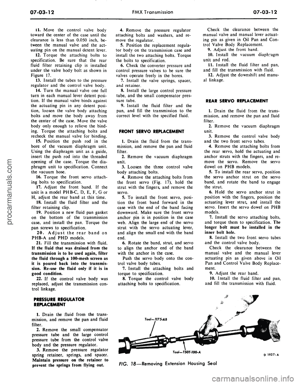
Too/~7?75-AB
7oo/-T50T-JOO-A
78—Removing Extension Housing Seal
D 1927-Aprocarmanuals.com
Page 361 of 413
07-03-21
FMX Transmission
07-03-21
Tool—1175-AB
Tool— T50T-100-A
D1962-A
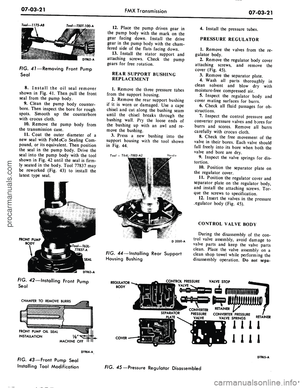
FIG. 41—Removing Front Pump
Seal
8. Install
the oil
seal remover
shown
in Fig. 41.
Then pull
the
front
seal from
the
pump body.
9. Clean
the
pump body counter-
bore.
Then inspect
the
bore
for
rough
spots.
Smooth
up the
counterbore
with crocus cloth.
10.
Remove
the
pump body from
the transmission case.
11.
Coat
the
outer diameter
of a
new seal with FoMoCo Sealing
Com-
pound,
or its
equivalent. Then position
the seal
in the
pump body. Drive
the
seal into
the
pump body with
the
tool
shown
in Fig. 42
until
the
seal
is
firm-
ly seated
in the
body. Tool 77837
may
be reworked
(Fig. 43) to
install
the
latest type seal.
FRONT PUMP
BODY
D1963-A
FIG. 42—Installing Front Pump
Seal
CHAMFER
TO
REMOVE BURRS
FRONT PUMP
OIL
SEAL
INSTALLATION
MACHINE
OFF
D1964-A
FIG.
43—
Front Pump Seal
Installing Tool Modification
12.
Place
the
pump driven gear
in
the pump body with
the
mark
on the
gear facing down. Install
the
drive
gear
in the
pump body with
the
cham-
fered side
of the
flats facing down.
13.
Install
the
stator support
and
attaching screws. Check
the
pump
gears
for
free rotation.
REAR SUPPORT BUSHING
REPLACEMENT
1.
Remove
the
three pressure tubes
from
the
support housing.
2.
Remove
the
rear support bushing
if
it is
worn
or
damaged.
Use a
cape
chisel
and cut
along
the
bushing seam
until
the
chisel breaks through
the
bushing wall.
Pry the
loose ends
of
the bushing
up
with
an awl and re-
move
the
bushing.
3.
Press
a new
bushing into
the
support housing with
the
tool shown
in
Fig. 44.
Too/
-
T64L-7003-A2
Handle
D 2050-A
FIG. 44—Installing Rear Support
Housing Bushing
4.
Install
the
pressure tubes.
PRESSURE REGULATOR
1.
Remove
the
valves from
the re-
gulator body.
2.
Remove
the
regulator body cover
attaching screws,
and
remove
the
cover
(Fig. 45).
3.
Remove
the
separator plate.
4.
Wash
all
parts thoroughly
in
clean solvent
and
blow
dry
with
moisture-free compressed
air.
5.
Inspect
the
regulator body
and
cover mating surfaces
for
burrs.
6. Check
all
fluid passages
for ob-
structions.
7.
Inspect
the
control pressure
and
converter pressure valves
and
bores
for
burrs
and
scores. Remove
all
burrs
carefully with crocus cloth.
8. Check
the
free movement
of the
valve
in
their bores. Each valve should
fall freely into
its
bore when both
the
valve
and
bore
are dry.
9. Inspect
the
valve springs
for dis-
tortion.
10.
Position
the
separator plate
on
the regulator cover.
11.
Position
the
regulator cover
and
separator plate
on the
regulator body,
and install
the
attaching screws.
Tor-
que
the
screws
to
specification.
12.
Insert
the
valves
in the
pressure
regulator body
(Fig. 45).
CONTROL VALVE BODY
During
the
disassembly
of the con-
trol valve assembly, avoid damage
to
valve parts
and
keep
the
valve parts
clean. Place
the
valve assembly
on a
clean shop towel while performing
the
disassembly operation.
Do not
sepa-
REGULATOR
BODY
CONTROL PRESSURE
VALVE
SEPARATOR
CONVERTER RETAINER
PRESSURE CONVERTER PRESSURE
VALVE SPRINGS
COVER
RETAINER
1111
1111
D1965-A
FIG. 45— Pressure Regulator Disassembledprocarmanuals.com
Page 368 of 413

07-03-28
FMX Transmission
07-03-28
CENTER
SUPPORT
ROTATE
CARRIER
COUNTER
CLOCKWISE
SAWTEETH IN
CLOCKWISE
DIRECTION
MOVE ROLLER
TOWARD CENTER
D 1291-D
FIG. 56—Planetary Clutch Installation in Carrier—Center Support
Not Chamfered
er between the large internal gear and
the transmission case. Note the indi-
cator reading. End play should be
0.010-0.029 inch (minimum end play
is preferred).
4.
Remove the indicator and the
tool from the extension housing.
5.
Install the one remaining front
pump attaching bolt and torque it to
specification.
FRONT SERVO
1.
Position the front band forward
in the case with the band ends up.
2.
Position the servo strut with the
slotted end aligned with the servo act-
uating lever, and with the small end
aligned with the band end. Rotate the
band, strut, and servo into position
engaging the anchor end of the band
with the anchor pin in the case.
3.
Locate the servo on the case, and
install the attaching bolts. Tighten the
attaching bolts only two or three
threads.
4.
Install the servo release tube.
REAR SERVO
12.
Install the output shaft, careful-
ly meshing the internal gear with the
pinions.
REAR SUPPORT
1.
Position the needle bearing and
retainer on the rear support (Fig. 24).
2.
Position a new rear support to
case gasket on the rear support. Re-
tain the gasket with transmission
fluid.
3.
Install the rear support. As the
support is installed, insert the tubes
into the case.
GOVERNOR
1.
Position the governor drive ball
in the pocket in the output shaft. Re-
tain the ball with transmission fluid.
2.
Install the governor assembly, al-
igning the groove with the ball in the
output shaft.
3.
Install the governor with the gov-
ernor body plate toward the front of
the vehicle (Fig. 23). Install the gover-
nor snap ring
EXTENSION HOUSING
1.
Insert the extension housing oil
seal re placer and pilot in the housing.
Position a new gasket to the extension
housing and install the extension
housing on the transmission case.
Coat the bolt threads with B5A-
19554-A sealer and install the exten-
sion housing attaching bolts, breather
tube clip, vacuum tube clip, and exter-
nal tooth lock washer. The lock wash-
ers must be installed with the rolled
edge toward the transmission case to
insure a tight seal.
2.
Torque the extension housing at-
taching bolts to specification.
3.
Install the lubrication tube.
FRONT PUMP
1.
Position a new front pump gask-
et in the counterbore of the transmis-
sion case.
2.
Install the front pump, aligning
the pump bolt holes with the holes in
the case. Install three of the front
pump attaching bolts and torque them
to specification.
TRANSMISSION END
PLAY CHECK
1.
Mount the dial indicator support
in a front pump bolt hole. Mount a
dial indicator on the support so that
the contact rests on the end of the tur-
bine shaft.
2.
Use a large screwdriver to pry
the front of the clutch drum toward
the rear of the transmission. Set the
dial indicator at zero.
3.
Remove the screwdriver and pry
the units toward the front of the
transmission by inserting a screwdriv-
1.
Position the servo anchor strut,
and rotate the rear band to engage the
strut.
2.
Position the servo actuating lever
strut with a finger, and then install the
servo and attaching bolts. Torque the
bolts to specification.
3.
Install the front servo apply
tube.
PRESSURE REGULATOR
BODY
1.
Install the pressure regulator
body and attaching bolts, and torque
the bolts to specifications.
2.
Install the control and converter
valve guides and springs. Install the
spring retainer.
CONTROL VALVE BODY
1.
Install the control valve assem-
bly, carefully aligning the servo tubes
with the control valve. Align the inner
downshift lever between the stop and
the downshift valve. Shift the manual
lever to the 1 position. Align the man-
ual valve with the actuating pin in the
manual detent lever. Do not tighten
the attaching bolts.
2.
Move the control valve body
toward the center of the case until the
clearance is less than 0.050 inch be-
tween the manual valve and the act-
uating pin on the manual detent lever.
3.
Torque the attaching bolts toprocarmanuals.com
Page 369 of 413
07-03-29
FMX Transmission
07-03-29
specification. Be sure that the rear
fluid screen retaining clip is installed
under the valve body bolt as shown in
Fig. 17.
4.
Install the large control pressure
tube in the valve body and regulator.
5.
Install the small control pressure
compensator tube in the valve body
and regulator.
6. Turn the manual valve one full
turn in each manual lever detent posi-
tion. If the manual valve binds against
the actuating pin in any detent posi-
tion, loosen the valve body attaching
bolts and move the body away from
the center of the case. Move the body
only enough to relieve the binding.
Torque the attaching bolts and check
the manual valve for binding.
7.
Torque the front servo attaching
bolts to specification.
FRONT AND REAR
BAND ADJUSTMENTS
Adjust the front and rear bands as
detailed in Section 2.
VACUUM DIAPHRAGM UNIT
1.
Position the control rod in the
bore of the vacuum diaphragm unit
and install the diaphragm unit. Make
sure the control rod enters the throttle
valve as the vacuum unit is installed.
2.
Torque the diaphragm unit to
specification.
FLUID FILTER
AND OIL PAN
1.
Position the fluid filter on the
rear clip so that the tang enters the
hole in the filter flange. Then, rotate
the filter (clockwise) until the grom-
met is over the pump inlet port of the
valve body regulator and press the fil-
ter down firmly. Install the filter re-
taining clip.
2.
Place a new gasket on the trans-
mission case and install the pan. In-
stall the attaching bolts and lock
washers and torque the bolts to speci-
fication.
If the converter and converter hous-
ing were removed from the transmis-
sion, install these components. Posi-
tion the transmission assembly on the
transmission jack, and refer to Trans-
mission Installation Procedures for in-
stalling the transmission.procarmanuals.com