1953 JEEP DJ wheel torque
[x] Cancel search: wheel torquePage 6 of 376
GENERAL
DATA
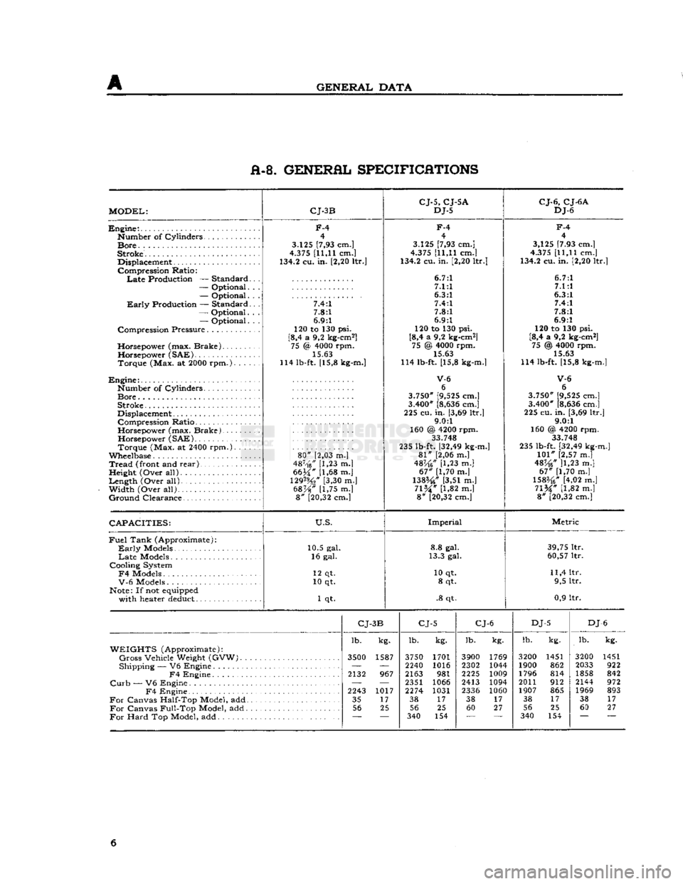
A-8. GENERAL SPECIFICATIONS
MODEL:
CJ-3B
CJ-5,
CJ-5A
DJ-5
CJ-6,
CJ-6A
DJ-6
Engine:.
Number
of
Cylinders
Bore.
.
Stroke.
Displacement
Compression
Ratio:
Late
Production —
Standard
—
Optional.
—
Optional.
Early
Production —
Standard
—
Optional.
—
Optional.
Compression
Pressure
Horsepower
(max.
Brake)
Horsepower
(SAE)
Torque
(Max. at 2000
rpm.).
. . .
Engine:
Number
of
Cylinders
Bore
Stroke
Displacement
Compression
Ratio
Horsepower
(max.
Brake).
Horsepower
(SAE)
Torque
(Max. at 2400
rpm.).
. . .
Wheelbase
Tread
(front and
rear)
,
Height
(Over
all)
Length
(Over
all).
Width
(Over
all)
Ground
Clearance
F-4
4
3.125 [7,93 cm.]
4.375 [11,11 cm.]
134.2 cu. in. [2,20 ltr.]
7.4:1 7.8:1
6.9:1
120 to 130 psi.
[8,4 a 9,2 kg-cm2] 75 <§ 4000 rpm.
15.63
114 lb-ft. [15,8 kg-m.]
80"
[2,03 m.]
487-'f6/' [1,23 m.|
6634" [1,68 m.j
129%"
[3,30 m.]
68%"
[1,75 m.] 8" [20,32 cm.]
F-4
4
3.125 [7,93 cm.]
4.375 [11,11 cm.]
134.2 cu. in. [2,20 ltr.]
6.7:1 7.1:1
6.3:1 7.4:1
7.8:1
6.9:1
120 to 130 psi.
[8,4 a 9,2 kg-cm2] 75 @ 4000 rpm. 15.63
114 lb-ft. [15,8 kg-m.]
V-6
6
3.750" [9,525 cm.]
3.400" [8,636 cm.]
225 cu.
in.
[3,69 ltr.] 9.0:1
160 @ 4200 rpm. 33.748
235 lb-ft. [32,49 kg-m.]
81"
[2,06 m.]
48K6"
[1,23 m.]
67"
[1,70 m.]
138%"
[3,51 m.]
71%"
[1,82 m.] 8" [20,32 cm.]
F-4
4
3,125 [7.93 cm.]
4.375 [11,11 cm.]
134.2 cu. in. [2,20 ltr.]
6.7:1 7.1:1
6.3:1 7.4:1
7.8:1
6.9:1
120 to 130 psi.
[8,4 a 9,2 kg-cm2] 75 @ 4000 rpm.
15.63
114 lb-ft. [15,8 kg-m.]
V-6
6
3.750" [9,525 cm.]
3.400" [8,636 cm.]
225 cu. in. [3,69 ltr.] 9.0:1
160 @, 4200 rpm. 33 748
235 lb-ft. [32,49 kg-m.]
101"
[2,57 m.]
48^6* ]1,23 m.]
67"
[1,70 m.]
1583/4" [4,02 m.]
71%"
[1,82 m.] 8" [20,32 cm.]
CAPACITIES:
U.S.
Imperial
Metric
Fuel
Tank
(Approximate):
Early
Models
Late
Models
Cooling
System
F4
Models
V-6
Models
Note: If not equipped
with
heater deduct 10.5 gal.
16 gal.
12 qt.
10 qt.
1 qt. 8.8 gal.
13.3 gal.
10 qt. 8 qt.
.8 qt. 39,75 ltr.
60,57 ltr.
11,4 ltr. 9,5 ltr.
0,9 ltr.
CJ-
3B
CJ-5
CJ-6
DJ-5
DJ
-6
lb. kg. lb.
kg. lb.
kg. lb.
kg. lb.
kg.
WEIGHTS
(Approximate):
Gross
Vehicle
Weight
(GVW).
3500
1587 3750 1701 3900 1769 3200 1451 3200 1451
Shipping
— V6
Engine
—
'—
2240 1016 2302 1044 1900 862 2033 922
F4
Engine
2132
967 2163
981 2225
1009 1796 814 1858 842
Curb
— V6
Engine
— —
2351 1066 2413 1094 2011 912 2144 972
F4
Engine
2243
1017 2274 1031
2336 1060 1907 865 1969 893
For
Canvas
Half-Top
Model, add 35
17 38
17 38
17 38
17 38 17
For
Canvas
Full-Top
Model, add 56
25 56 25 60 27 56 25 60 27
For
Hard
Top Model, add
~~
340
154 340 154 6
Page 12 of 376
B
LUBRICATION B-3.
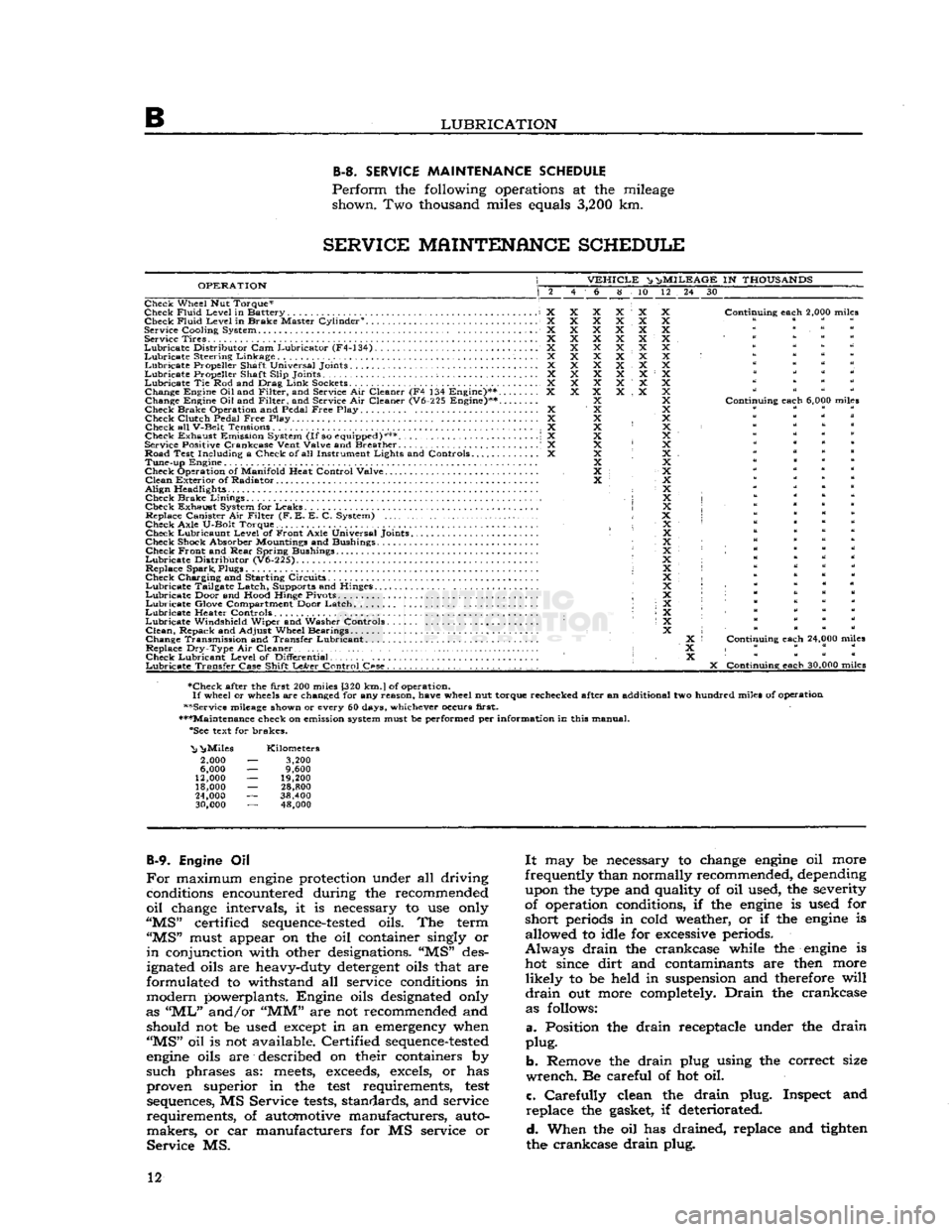
SERVICE
MAINTENANCE
SCHEDULE
Perform
the following operations at the mileage shown. Two thousand miles equals
3,200
km.
SERVICE
MAINTENANCE
SCHEDULE
OPERATION
VEHICLE
^ n>
MILEAGE
IN
THOUSANDS
6 8 10 12 24 30
Check Wheel Nut Torque*
Check
Fluid
Level
in Battery X Check
Fluid
Level
in Brake Master Cylinder0. X
Service
Cooling
System X Service Tires X
Lubricate
Distributor
Cam Lubricator (F4-134) X
Lubricate
Steering Linkage X
Lubricate
Propeller Shaft Universal Joints X
Lubricate
Propeller Shaft
Slip
Joints ; X
Lubricate
Tie Rod and Drag
Link
Sockets................................... X Change Engine
Oil
and
Filter,
and Service Air Cleaner (F4 134 Engine)** X
Change Engine Oil and
Filter,
and Service Air Cleaner (V6-225 Engine)**....
Check Brake Operation and Pedal
Free
Play X Check
Clutch
Pedal
Free
Play. .... X
Check all
V-Belt
Tensions X
Check Exhaust Emission System
(If
so equipped)*** \ X
Service Positive
Crankcase
Vent
Valve
and Breather . .' X
Road Test
Including
a Check of all Instrument
Lights
and Controls X Tune-up Engine
Check Operation of
Manifold
Heat
Control
Valve
Clean
Exterior of Radiator
Align
Headlights • Check Brake
Linings
,
Check Exhaust System for Leaks Replace Canister Air
Filter
(F. E. E. C. System)
Check
Axle
U-Bolt
Torque. Check Lubricaunt
Level
of Front
Axle
Universal Joints
Check Shock Absorber Mountings and Bushings Check Front and
Rear
Spring Bushings
Lubricate
Distributor
(V6-225).
Replace Spark, Plugs
Check Charging and Starting Circuits
Lubricate
Tailgate Latch, Supports and Hinges.
Lubricate
Door and
Hood
Hinge Pivots ;
Lubricate
Glove Compartment Door Latch
Lubricate
Heater Controls •
Lubricate
Windshield
Wiper and Washer Controls
Clean,
Repack and
Adjust
Wheel Bearings
Change Transmission and Transfer Lubricant. .
Replace
Dry-Type
Air Cleaner • Check Lubricant
Level
of
Differential
Lubricate
Transfer
Case
Shift
LeArer
Control
C«se.
. , . . . . . . . .
Continuing
each
2,000 miles
Continuing
each
6,000 miles
Continuing
each
24,000 miles
X
Continuing
each
30,000 miles
•Check after the
first
200 miles [320
km.
J
of operation.
If
wheel or wheels are changed for any
reason,
have
wheel nut torque rechecked after an additional two hundred miles of operation
••Service mileage shown or every 60 days, whichever occurs
first.
•••Maintenance check on emission system must be performed per
information
in this manual. "See text for brakes.
"Nj
^Miles
2,000
6,000
12,000
18,000
24,000
30,000
Kilometers
3,200
9,600
19,200
28,800
38,400 48,000
B-9.
Engine Oil
For
maximum
engine
protection under all driving conditions encountered during the recommended
oil
change intervals, it is necessary to use only
"MS"
certified
sequence-tested
oils. The term
"MS"
must appear on the oil container singly or
in
conjunction with other designations. "MS" des
ignated oils are heavy-duty detergent oils that are
formulated to withstand all service conditions in
modern powerplants. Engine oils designated only
as
"ML"
and/or
"MM"
are not recommended and should not be used except in an emergency when
"MS"
oil is not available. Certified
sequence-tested
engine
oils are described on their containers by
such
phrases as:
meets,
exceeds,
excels, or has
proven superior in the
test
requirements,
test
sequences, MS Service
tests,
standards, and service
requirements,
of automotive manufacturers, auto
makers,
or car manufacturers for MS service or
Service
MS.
It
may be necessary to change
engine
oil more
frequently than normally recommended, depending upon the type and quality of oil used, the severity
of operation conditions, if the
engine
is used for
short
periods in cold weather, or if the
engine
is allowed to idle for excessive periods.
Always
drain
the crankcase while the
engine
is hot since
dirt
and contaminants are then more
likely
to be held in suspension and therefore
will
drain
out more completely.
Drain
the crankcase as follows:
a.
Position the
drain
receptacle under the
drain
plug.
b.
Remove the
drain
plug using the correct size
wrench.
Be careful of hot oil.
c.
Carefully
clean the
drain
plug. Inspect and
replace
the gasket, if deteriorated.
d.
When the oil has drained, replace and tighten
the crankcase
drain
plug. 12
Page 16 of 376
B
LUBRICATION
Note:
Hard
shifting of the transmission gear in
cold weather is a positive indication that the
lubri
cant
is of the wrong viscosity or of poor quality
which
allows it to congeal.
B-38.
Optional
4-Speed
Transmission
and
Transfer Case
The
four-speed transmission and transfer case re
quire
separate lubrication for each unit as
they
have no cross-over oil passage. At each transmission
service check, the
fill
plugs of
both
four-speed
transmission
and transfer case should be pulled
and
the lubricant refilled to level if necessary.
B-39.
Transfer
Case
Linkage
The
transfer case shift linkage should be lubricated
periodically.
All
bearing surfaces that are assembled
with
studs and cotter pins should be disassembled, cleaned, and coated with a
good
waterproof grease.
The
bearing surfaces that cannot be disassembled
should be lubricated with a lubricant that
will
penetrate the bearing
area.
These bearings include
the two on the cross shaft assembly and the
threaded stud.
The
type
of penetrating lubricant recommended is
DuPont
"PM 7", No. 2911, or its equivalent.
B-40.
Brake Master Cylinder
Clean
the top of the
fill
cap and also the housing
area
around it. Remove the cap and observe the
fluid
level. It should be
half
an inch
below
the top
of the fill-hole. If not, add brake fluid to
half
inch
[1,3 cm.]
below
the top of the fill-hole. Use
only heavy-duty brake fluid conforming to speci
fication
SAE-J-1703.
Be sure to handle the brake
fluid
in clean dispensers and containers that
will
not introduce even the
slightest
amount of other
liquids
or foreign particles. Replace and tighten
the
fill
cap.
B-41.
Adjust Brakes
Refer
to Section P.
B-42.
Brake Linings
Refer
to Section P.
B-43.
Adjust Clutch
Refer
to Section I.
B-44.
Clutch Cross Shaft (Lever Type)
Lubricate
the clutch cross shaft in accordance with
specifications given in the
Lubrication
chart: see
Item
1. Chassis Bearings.
B-45.
Tie Rod and Drag
Link
Sockets
The
tie rod and drag
link
sockets
are equipped
with
lubrication
fittings
and should be lubricated
per
specifications given in the
Lubrication
chart: see Item 1. Chassis Bearings.
B-46.
Front
and
Rear Spring
Bushings
The
condition of the spring bushings is indicated
by the alignment of the spring pivot and spring
shackle
bolts.
Check
the alignment of
these
bolts,
and
check that nuts are
tightened
securely.
B-47.
Spring
Shackles
Rubber
bushings are provided on the spring
shackles.
These rubber bushings have no lubrication
fitting and it is very important that
they
never be lubricated.
B-48.
Shock Absorbers
Visually
check for broken mounts or bolts, worn
or
missing bushings on the shock absorbers. Refer
to Section S.
B-49.
Front and
Rear
Axle
U-Bolts
Torque
the front and
rear
axle U-bolts. Refer to Section S.
B-50. Front
and
Rear
Axle
Differentials
—
Lubricant Levels
The
lubricant
level of all front and
rear
differentials should be at the level of the fill-hole.
B-51.
Front and
Rear
Axle
Differentials
—
Changing
Lubricant
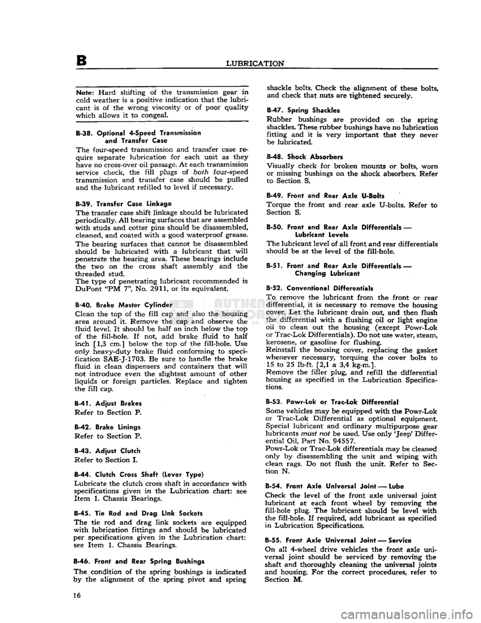
B-52.
Conventional Differentials
To
remove the lubricant from the front or
rear
differential,
it is necessary to remove the housing cover. Let the lubricant
drain
out, and then flush
the differential with a flushing oil or light
engine
oil
to clean out the housing
(except
Powr-Lok
or
Trac-Lok
Differentials). Do not use water, steam,
kerosene, or
gasoline
for flushing.
Reinstall
the housing cover, replacing the gasket whenever necessary, torquing the cover
bolts
to 15 to 25 lb-ft. [2,1 a 3,4 kg-m.].
Remove the filler plug, and
refill
the differential
housing as specified in the
Lubrication
Specifica
tions.
B-53.
Powr-Lok
or
Trac-Lok Differential
Some vehicles may be equipped with the
Powr-Lok
or
Trac-Lok
Differential as optional equipment.
Special
lubricant and ordinary multipurpose gear
lubricants
must
not be used. Use only
'Jeep*
Differ
ential
Oil,
Part
No. 94557.
Powr-Lok
or
Trac-Lok
differentials may be cleaned
only by disassembling the unit and wiping with
clean
rags. Do not flush the unit. Refer to Sec
tion N.
B-54.
Front Axle Universal Joint
—
Lube
Check
the level of the front axle universal joint
lubricant
at each front wheel by removing the
fill-hole plug. The lubricant should be level with
the fill-hole. If required, add lubricant as specified
in
Lubrication
Specifications.
B-55.
Front
Axle
Universal
Joint
— Service
On
all 4-wheel drive vehicles the front axle
uni
versal
joint should be serviced by removing the shaft and thoroughly cleaning the universal joints
and
housing. For the correct procedures, refer to
Section M. 16
Page 54 of 376
D
HURRICANE
F4
ENGINE
against the hub of the crankshaft pulley.
Timing
gears are accessible for inspection or replacement
with
the
engine
installed in the vehicle after re moving the radiator, belt drive pulley, and timing
cover.
Should
it be necessary to replace the timing gears, attention must be given to the end float of both
the camshaft and crankshaft and to the running
clearance
of both gears. It is also advisable to
check
both the oil jet and oil passage to the
crank
shaft front bearing to be sure that they are clear.
D-55.
Inspection and
Repair
Check
the general condition of both gears and
inspect for evidence of excessive wear. Replace
excessively worn or damaged gears. Inspect the
cover and replace if bent or damaged. It is recom mended that the crankshaft oil seal in the cover
be replaced when the cover is removed to ensure a
good
seal around the crankshaft. To replace this
seal
with the
engine
in the vehicle
requires
removing
the radiator and water pump.
D-56.
Valves, Springs, and Guides
The
exhaust valves seat on the top of the cylinder
block
with the
stems
extending down through
replaceable valve guides. The exhaust valves are actuated by the camshaft through exhaust valve
tappets. The exhaust valve springs are assembled
and
locked on the lower end of the exhaust valve
stems. The retaining locks are the split type, which
fit in a recess on the valve
stems
and into the taper
in
the valve spring retainers.
Adjustment
of exhaust valves is by means of the
adjusting
screw threaded into the upper end of the
exhaust valve tappets. An exhaust valve rotator used as a valve spring retainer is installed on the
lower end of the exhaust valve.
This
valve rotator,
known
as "Roto Cap", is a spring-loaded
ball
bearing
device. On each lift, or opening stroke of
a
valve, the rotator
gives
the valve a slight positive
clockwise rotation.
The
intake valves operate in valve
guides
in the
cylinder
head and are actuated by rocker arms.
The
rocker arms are actuated by valve push rods
and
the intake valve tappets. The intake valve
springs,
the intake valve spring retainers, and the
intake
valve spring retainer locks make up the
remainder
of the valve operating parts. An intake
valve spring retainer oil seal which encircles the
upper
end of the intake valve
between
the valve
locks and the upper end of the valve spring re
tainer,
controls the passage of oil along the valve
stem and guide.
Note:
When
engine
trouble indicates defective
valves as a possible source of trouble, also check
all
vacuum line connections for possible leaks.
D-57.
Inspection of Valves, Springs,
and
Guides
Clean
the valves on a wire wheel, making sure that
all
carbon is removed from the top and the under
side of the heads and that all gum and varnish
deposits
are removed from the stems.
Polish
the valve
stems
with steel wool or crocus
cloth.
Visually
inspect all valves for warpage,
cracks,
or excessive burning and discard if one of
these
conditions exists. Replace any worn, pitted,
or
corroded valves that cannot be cleaned with a
wire
brush.
Replace any valves when
seats
are pitted, burned, or corroded so badly that they
cannot be cleaned up with a light refacing on a valve refacing machine.
Replace
valves with marks of scoring or abrasion visible on the stem. Replace any valves with bent
stems
which
will
be apparent when the valve is
mounted in the valve refacing machine.
Note:
Use only hard-face exhaust valves for
replacement.
Examine
the
stems
of valves which employ the
ball
bearing rotators.
Wear
marks around the
cir
cumference of the
stems
indicates that the valve is
rotating satisfactorily.
Vertical
heavy pressure
areas
indicate that the valve is not rotating and the valve spring retainer (Roto
Cap)
should be replaced
if
at fault.
Check
the diameter of the valve stem at two or three places along the length of the stem
with
a micrometer. The intake valve stem diameter is .3733" to .3738" [9,482 a
9,495
mm.]. The
exhaust valve stem diameter is .371" to .372"
[9,423
a
9,449
mm.].
Note:
Exhaust
and intake valve springs are
similar
in appearance. They must not be inter
changed as they have different spring
charac
teristics.
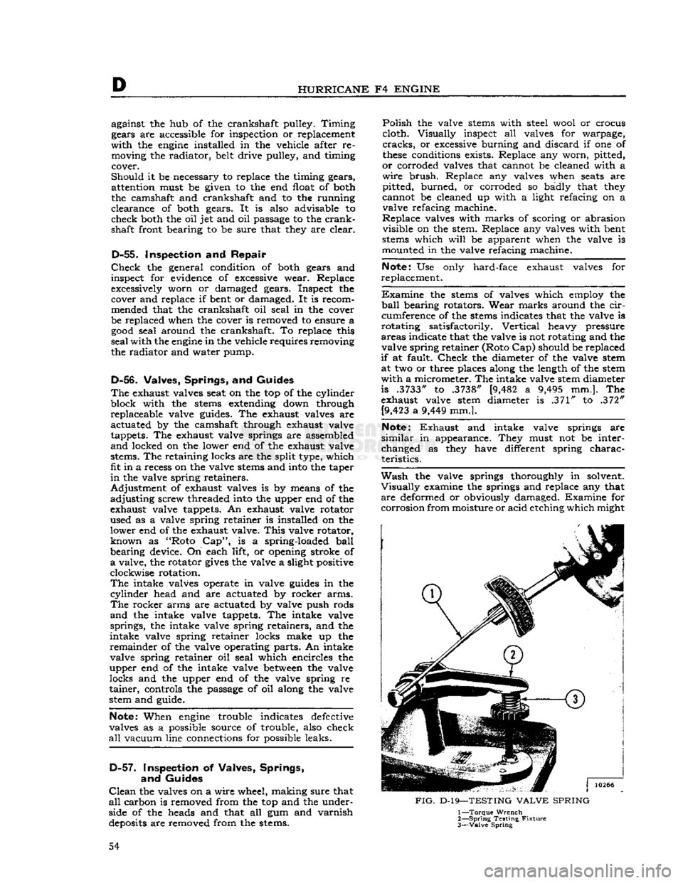
Wash
the valve springs thoroughly in solvent.
Visually
examine the springs and replace any that
are
deformed or obviously damaged. Examine for
corrosion
from moisture or acid etching which might
FIG.
D-19—TESTING
VALVE
SPRING
1—
Torque
Wrench
2—
Spring
Testing
Fixture
3—
Valve
Spring
54
Page 68 of 376
D
HURRICANE
F4
ENGINE
D-101.
Install
Manifold
If
manifold studs were removed for replacement,
apply sealer on the stud threads
before
installing
a
new stud.
See Section Fl for exhaust emission controlled
engines.
Make
certain that no foreign objects are inside the manifold and that all
passages
are clear. Place a
new set of manifold
gaskets
in position on the side
of the cylinder block.
Then,
carefully slide the manifold
onto
the studs and against the cylinder block being careful not to damage the gaskets.
Torque
all manifold attaching nuts evenly 29 to
35 lb-ft. [4,0 a 4,8 kg-m.].
D-102.
Install
Oil
Filler
Tube
When
installing the oil filler tube, be sure that the
beveled lower end is away from the crankshaft.
Place a
piece
of
hard
wood
over the top of the
tube
to prevent damage to the cap gasket seat.
D-103.
Install
Water Pump
Make
certain that the mating surfaces of the water pump and the cylinder block are clean and smooth.
Install
the gasket on the
flange
of the pump and
install
the pump in position on the cylinder block.
Torque
the water pump attaching
bolts
alternately
and
evenly 12 to 17 lb-ft. [1,7 a 2,3 kg-m.].
D-104.
Install
Water Outlet Fitting
Install
the thermostat and the water
outlet
fitting.
Torque
the water
outlet
fitting attaching
bolts
20
to 25 lb-ft. [2,8 a 3,4 kg-m.].
FIG.
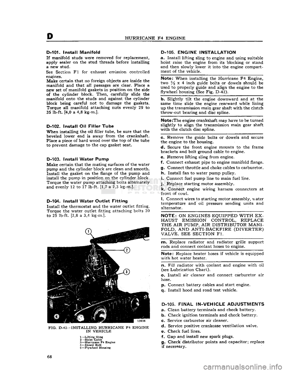
D-42—INSTALLING HURRICANE F4 ENGINE
IN
VEHICLE
1—
Lifting
Sling
2— Hoist
Cable
3—
Hurricane
F4 Engine
4— Dowel Bolt
5—
Flywheel
Housing
D-105.
ENGINE INSTALLATION
a.
Install
lifting sling to
engine
and using suitable hoist raise the
engine
from its blocking or stand
and
then slowly lower it
into
the
engine
compartment of the vehicle.
Note:
When installing the
Hurricane
F4 Engine,
two % x 4 inch
guide
bolts
or
dowels
should be
used to properly
guide
and align the
engine
to the
flywheel housing (See Fig. D-42).
b. Slightly tilt the
engine
downward and at the
same time slide the
engine
rearward
while lining up the transmission main gear shaft with the clutch
throw-out bearing and disc spline.
Note
:The
engine
crankshaft may have to be turned
slightly to align the transmission main gear shaft
with the clutch disc spline.
c. Remove the
guide
bolts
or
dowels
and secure
the
engine
to the housing.
d.
Secure the front
engine
mounts to the frame brackets and
bolt
ground cable to
engine.
e. Remove lifting sling from
engine.
f. Connect exhaust pipe to
engine
manifold flange.
g. Connect throttle and choke cables to carburetor.
h.
Install
fan to water pump pulley.
i.
Connect fuel pump line to main fuel line,
j.
Replace starting motor assembly. k. Connect
engine
wiring harness connectors at
front of cowl.
I.
Connect wires to starting motor assembly, water
temperature and oil pressure sending units and alternator.
NOTE:
ON
ENGINES EQUIPPED WITH EX
HAUST
EMISSION CONTROL,
REPLACE
THE
AIR
PUMP,
AIR
DISTRIBUTOR
MANI
FOLD,
AND
ANTI-BACKFIRE (DIVERTER)
VALVE.
SEE
SECTION
Fl.
m. Replace radiator and radiator grille support
rods and connect coolant
hoses
to
engine.
Note:
Replace heater
hoses
if vehicle is equipped
with hot water heater.
n. Fill
radiator with coolant and
engine
with oil
(see
Lubrication
Chart).
o.
Install
air cleaner and connect carburetor air
hose.
p. Connect battery cables and start
engine,
q.
Install
hood
and road
test
vehicle.
D-103.
FINAL
IN-VEHICLE
ADJUSTMENTS
a.
Clean
battery terminals and check battery. b.
Check
ignition terminals and check battery.
c. Service carburetor air cleaner.
d.
Service positive crankcase ventilation valve.
e.
Check
fuel lines. f. Gap and install new
spark
plugs.
g.
Check
distributor
points
and capacitor; replace
if
necessary. 68
Page 79 of 376

'Jeep*
UNIVERSAL SERIES SERVICE
MANUAL
Dl
12710
FIG.
D1
-3—HYDRAULIC VALVE
LIFTER
ASSEMBLY, CROSS-SECTIONAL VIEW
1—
Snap
Ring
6—Ball Retainer
2— Rod
Seat
7—Plunger Spring
3—
Oil
Inlets
8—Lifter
Body
4—
Plunger
9—Bronzed
Cap
5— Feed
Hole
sages
in the block and cylinder head.
The
water cooled system is pressurized to provide efficient
engine
cooling. It consists of a centrifugal-
type water pump, mounted on the timing chain cover, and is driven by the
engine
fan pulley. The
pump provides coolant flow equally to both
cylin
der banks under control of a thermostat. Coolant
flow is around the cylinders and through the
cylinder
head to dispel the heat of combustion in
the engine.
Dl-3.
Engine Mounts
The
engine-transmission unit is mounted to the chassis at three points by rubber pads. The two
front mounts are bolted to the
engine
cylinder
block and the frame members. These mounts sup port most of the
engine
weight, and absorb
vibra
tion which would otherwise be caused by changes
in
engine
output torque. The single
rear
mount is
placed
between
the transmission and the trans mission support. It supports part of the engine'
and
transmission weight, and locates the
rear
of
the
engine
with respect to the centerline of the
vehicle.
Dl-4. ENGINE REMOVAL
To
remove the
engine
from the vehicle follow the
procedurers listed below:
a.
Remove hood. b. Disconnect battery cables from battery and
engine. c. Remove air cleaner.
d.
Drain
coolant from radiator and engine.
e.
Drain
engine
oil.
f. Disconnect alternator wiring harness from con nector at regulator.
cj.
Disconnect the fuel evaporative purge line con nected to the
P.C.V.
valve.
h.
Disconnect upper and lower radiator
hoses
from
the engine.
i.
Remove right and left radiator support
bars,
j.
Remove radiator from the vehicle.
k.
Disconnect
engine
wiring harnesses from con
nectors located on
engine
firewall.
I.
On
engines
equipped with exhaust emission con
trol,
remove the air pump, air distribution manifold,
and
anti-backfire (gulp) valve. See Section F2 for
procedure.
m.
Disconnect battery cable and wiring from en
gine
starter assembly.
n.
Remove
engine
starter assembly from engine,
o.
Disconnect
engine
fuel
hoses
from fuel lines at
right
frame
rail,
p. Plug fuel lines.
q.
Disconnect choke cable from carburetor and cable support bracket mounted on engine,
r.
Disconnect exhaust pipes from right and left
engine
manifolds.
s. Place
jack
under transmission and support trans
mission weight.
f. Remove
bolts
securing
engine
to front motor mounts.
u.
Attach suitable sling to
engine
lifting
eyes
and,
using hoist, support
engine
weight.
v. Remove
bolts
securing
engine
to flywheel housing.
w. Raise
engine
slightly and slide
engine
forward
to remove transmission main shaft from clutch plate spline.
Note:
Engine and transmission must be raised
slightly to release the main shaft from the clutch
plate while sliding the
engine
forward.
x. When
engine
is free of transmission shaft raise
engine
and remove from vehicle,
y. Place
engine
on suitable blocking or
engine
stand and remove sling from engine.
Dl-5.
ENGINE DISASSEMBLY
Engine
disassembly is presented in the sequence to be followed when the
engine
is to be completely
overhauled after removal from the vehicle. Some of the operations of the procedure are also applicable separately with the
engine
in the vehicle,
provided that wherever necessary the part of the
engine
to be worked on is first made accessible by removal of
engine
accessories or other parts.
When
the disassembly operations are performed
with
the
engine
out of the vehicle, it is assumed,
in
this procedure, that all of the accessories have
been removed
prior
to starting the disassembly and
the oil has been drained.
Page 97 of 376

'Jeep'
UNIVERSAL
SERIES SERVICE
MANUAL
Dl
size have
been
selected. If necessary, check or
select
connecting rod bearings as described in Par. Dl-49.
Note:
When a piston and connecting rod assembly
is properly installed, the oil spurt
hole
in the con necting rod
will
face the camshaft. The rib on the
edge
of the bearing cap
will
be on the same side
as the conical
boss
on the connecting rod web;
these
marks (rib and boss)
will
be toward the other
connecting rod on the same crankpin. The notch
on the piston
will
face the front of the
engine.
a.
Be certain that cylinder bores, pistons, connect
ing rod bearings and crankshaft journals are absolutely clean. Coat all bearing surfaces with
engine
oil.
b. Before installing a piston and connecting rod as
sembly into its bore, rotate the crankshaft so that
the corresponding crankpin is moved downward, away from the cylinder bore.
c. Remove bearing cap from connecting rod. With
upper bearing half seated in connecting rod, install connecting rod guides. These
guides
hold the upper
bearing half in place and prevent damage to the
crankshaft
crankpin during installation of the con
necting rod and piston assembly.
d.
Be certain that the gap in the oil ring rails faces
upward,
toward center of
engine.
Gaps of the com
pression rings shall not be aligned with each other
or
with the oil ring
rails.
e. Lubricate the piston and rings. Compress the
rings with a suitable piston ring compressor; install
the piston and connecting rod assembly from top of cylinder bore. Refer to Fig. Dl-33.
f.
Install
bearing cap, with lower bearing half, on connecting rod. Torque bolt nuts to 30 to 40 lb-ft. [4,1 a 5,5 kg-m.].
g.
Install
all other piston and connecting rod as
semblies in same manner.
h.
Check
end clearance
between
connecting rods
on each crankpin with a feeler
gauge.
Clearance should be .005,/ to .012" [0,127 a
0,305
mm.].
Dl-76.
Install
Oil
Pump
Intake
Pipe
and
Screen Assembly
Check
mating surfaces of oil pump intake pipe
and
engine
cylinder block to be certain that they
are
clean. Secure the pipe and screen assembly,
with a new gasket, to
engine
cylinder block with two attaching screws. See Fig. Dl-34. Torque screws 6 to 9 lb-ft. [0,83 a 1,24 kg-m.].
Dl-77.
Install
Oil Pan
Refer
to Fig. Dl-35.
Be
certain the flange surface of oil pan and cor
responding surface of
engine
cylinder block are
clean.
Install
a new oil pan gasket on the cylinder
block.
Secure
oil pan to cylinder block with mount ing bolts. Torque
bolts
10 to 15 lb-ft [1,4 a 2,1
kg-m.].
Dl-78.
Install
Flywheel
Refer
to Fig. Dl-7.
a.
Check
flywheel flange of
engine
crankshaft and corresponding surface of flywheel to
be
certain that
FIG.
Dl-33—INSTALLING
PISTON
AND
CONNECTING
ROD
ASSEMBLY
1—Ring
Compressor
FIG.
Dl-34-^-OIL
PUMP
INTAKE PIPE
AND
SCREEN
INSTALLATION
1—Pipe and Screen
97
Page 99 of 376

'Jeep'
UNIVERSAL SERIES SERVICE
MANUAL
Dl
both are clean. Any foreign material on either of
these
surfaces
will
cause flywheel run out and en
gine
vibration. Position flywheel to crankshaft and
secure with six mounting bolts. Torque mounting
bolts
50 to 65 lb-ft. [6,91 a 8,98 kg-m.].
Note:
Flywheel mounting
bolts
are unevenly
spaced so that flywheel can be installed in only
one position.
This
assures correct balance of fly
wheel and crankshaft.
b.
Mount a
dial
indicator on flywheel housing
flange of cylinder block and index its plunger to
the flywheel surface. Measure flywheel run out.
Maximum
allowable run out is .015"
[0,381
mm.].
Dl-82.
Install
Cylinder
Head Assembly
Refer
to Fig. Dl-9.
a.
Wipe cylinder head face of
engine
cylinder
block, and be certain no foreign material has fallen
into the cylinder bores, bolt holes, or in the valve
lifter
area.
It is
good
practice to clean out bolt
holes
with compressed air.
b.
Install
a new cylinder head gasket on the
cylin
der
block. Dowels in the block
will
hold the gasket
in
position. Always handle gaskets carefully to
avoid
kinking or damage to the surface treatment
of the gasket. Apply Perfect Seal Aerosol
Spray
Sealer
Part
No.
994757
on cylinder head gaskets.
Dl-79.
Install
Clutch
and Flywheel Housing
a.
Note
marks made on clutch assembly and fly
wheel during
engine
disassembly. Position clutch
assembly to flywheel, according to
marks,
and
fasten
loosely
with six attaching bolts. Torque
bolts
in rotation, one
turn
at a time, to 30 to 40 lb-ft. [4,1 a 5,5 kg-m.].
b.
Engage fork of clutch linkage to clutch and
position flywheel housing to
engine
cylinder block.
Secure
housing to block with six mounting bolts.
Torque
bolts
30 to 40 lb-ft. [4,1 a 5,5 kg-m.].
D1-80.
Install
Camshaft
Insert
camshaft into camshaft bearings of
engine
cylinder
block carefully to avoid damage to bear
ing surfaces. Make certain camshaft journals are
properly
seated in bearings.
12695
FIG.
D1-36—CAMSHAFT
AND
VALVE LINKAGE
1—
Rocker
Arm
2—
Push
Rod 3—
Valve
Lifter
4—
Camshaft
14203
FIG.
Dl-37—CYLINDER
HEAD
BOLT TIGHTENING SEQUENCE c.
Clean
gasket surface of cylinder head and care
fully
place on the
engine
block dowel pins.
d.
Clean
and lubricate the cylinder head
bolts
with
a
sealing compound
(Part
No. 994757, or equiv
alent).
e.
Install,
and alternately tighten the head bolts,
a
little at a time, in the sequence shown in Fig.
Dl-37.
Torque
bolts
65 to 85 lb-ft. [9,0 a 11,8
kg-m.].
f.
Tilt
the rocker arms toward the push rods and locate the top of each push rod in its rocker arm
seat.
g.
Mount the rocker arm and shaft assembly, tightening the bracket
bolts
a little at a time.
Torque
the bracket
bolts
25 to 35 lb-ft. [3,5 a 4,8
kg-m.].
Do not overtighten.
h.
See Section Fl and F2 for
engines
equipped
with
exhaust emission control.
D1-81.
Install
Valve Lifter
and Push Rod
Make
certain valve lifter guide
holes
and adjacent
area
of cylinder block are clean.
Liberally
lubricate
the camshaft and valve lifter bores with
engine
oil,
and install valve lifters.
Each
valve lifter must slide freely in its guide hole. See Fig. Dl-36.
Dl-83.
Install
Rocker Arm Cover
Install
a new gasket on each rocker arm cover.
Secure
each rocker arm cover to corresponding
cylinder
head with four attaching screws.
Install
the positive crankcase ventilation valve on right
rocker
arm cover. 99