1900 MITSUBISHI DIAMANTE transmission
[x] Cancel search: transmissionPage 2 of 408
.
1-2 GENERALINFORMATIONAND MAINTENANCE
Chitton’s Total Car Care manual for the 199M10
Mitsubishi Mirage, Galant and Diamante is intended
to help you learn more about the inner workings of
your vehicle while saving you money on its upkeep
and operation.
The beginning of the book will likely be referred to
the most, since that is where you will find information
for maintenance and tune-up. The other sections deal
with the more complex systems of your vehicle. Oper-
ating systems from engine through brakes are cov-
ered to the extent that the average do-it-yourselfer be-
comes mechanically involved. This book will not
explain such things as rebuilding a differential for the
simple reason that the expertise required and the in-
vestment in special tools make this task uneconomi-
cal. It will, however, give you detailed instructions to
help you change your own brake pads and shoes, re-
place spark plugs, and perform many more jobs that
can save you money, give you personal satisfaction
and help you avoid expensive problems.
A secondary purpose of this book is a reference for
owners who want to understand their vehicle and/or
their mechanics better. In this case, no tools at all are
required.
Before removing any bolts, read through the entire
procedure. This will give you the overall view of what
tools and supplies will be required. There is nothing
more frustrating than having to walk to the bus stop
on Monday morning because you were short one bolt
on Sunday afternoon. So read ahead and plan ahead.
Each operation should be approached logically and
all procedures thoroughly understood before attempt-
ing any work.
All sections contain adjustments, maintenance, re-
moval and installation procedures, and in some cases,
repair or overhaul procedures. When repair is not con-
sidered practical, we tell you how to remove the part
and then how to install the new or rebuilt replacement.
In this way, you at least save labor costs. “Backyard”
repair of some components is just not practical.
Many procedures in this book require you to “label
and disconnect. . ” a group of lines, hoses or wires.
Don’t be lulled into thinking you can remember where
everything goes-you won’t. If you hook up vacuum
or fuel lines incorrectly, the vehicle may run poorly, if
at all. If you hook up electrical wiring incorrectly, you
may instantly learn a very expensive lesson.
You don’t need to know the official or engineering
name for each hose or line. A piece of masking tape
on the hose and a piece on its fitting will allow you to
assign your own label such as the letter A or a short name. As long as you remember your own code, the
lines can be reconnected by matching similar letters
or names. Do remember that tape will dissolve in
gasolrne or other fluids; if a component is to be
washed or cleaned, use another method of identifica-
tion. A permanent felt-tipped marker or a metal scribe
can be very handy for marking metal parts. Remove
any tape or paper labels after assembly.
It’s necessary to mention the difference between
maintenance and repair Maintenance includes rou-
tine inspections, adjustments, and replacement of
parts which show signs of normal wear Maintenance
compensates for wear or deterioration. Repair implies
that something has broken or is not working. A need
for repair is often caused by lack of maintenance. Ex-
ample, draining and refilling the automatic transaxle
fluid is maintenance recommended by the manufac-
turer at specific mileage intervals. Failure to do this
can shorten the life of the transmission/transaxle, re-
quiring very expensive repairs. While no maintenance
program can prevent items from breaking or wearing
out, a general rule can be stated: MAINTENANCE IS
CHEAPER THAN REPAIR.
Two basic mechanrc’s rules should be mentioned
here. First, whenever the left side of the vehicle or en-
gine is referred to, it is meant to specify the drivers
side. Conversely, the right side of the vehicle means
the passengers side. Second, screws and bolts are
removed by turning counterclockwise, and tightened
by turning clockwrse unless specifically noted.
Safety is always the most important rule. Con-
stantly be aware of the dangers involved in working
on an automobile and take the proper precautions.
See the informatron in this section regarding SER-
VICING YOUR VEHICLE SAFELY and the SAFETY
NOTICE on the acknowledgment page.
Pay attention to the instructions provided. There
are 3 common mistakes in mechanical work:
1. Incorrect order of assembly, disassembly or
adjustment. When taking something apart or putting
it together, performing steps in the wrong order usu-
ally just costs you extra time; however, it CAN break
something. Read the entire procedure before begin-
ning disassembly. Perform everything in the order in
which the instructions say you should, even if you
can’t immedrately see a reason for it. When you’re
taking apart something that is very intricate, you
might want to draw a picture of how it looks when as-
sembled at one point in order to make sure you get everything back in its proper position. We will supply
exploded views whenever possible. When making
adjustments, perform them in the proper order. One
adjustment possibly will affect another.
2. Overtorquing (or undertorquing). While it is
more common for overtorquing to cause damage,
undertorquing may allow a fastener to vibrate loose
causing serious damage. Especially when dealing
with aluminum parts, pay attention to torque specifi-
cations and utilize a torque wrench in assembly. If a
torque figure is not available, remember that if you
are using the right tool to perform the job, you will
probably not have to strain yourself to get a fastener
tight enough. The pitch of most threads is so slight
that the tension you put on the wrench will be multi-
plied many times in actual force on what you are
tightening. A good example of how critical torque is
can be seen in the case of spark plug installation, es-
pecially where you are putting the plug into an alu-
minum cylinder head. Too little torque can fail to
crush the gasket, causing leakage of combustion
gases and consequent overheating of the plug and
engine parts. Too much torque can damage the
threads or distort the plug, changing the spark gap.
There are many commercial products available for
ensuring that fasteners won’t come loose, even if they
are not torqued just right (a very common brand is
Loctite? If you’re worried
about getting something
together tight enough to hold, but loose enough to
avoid mechanical damage during assembly, one of
these products might offer substantial insurance. Be-
fore choosing a threadlocking compound, read the
label on the package and make sure the product is
compatible with the materials, fluids, etc. involved.
3. Crossthreading. This occurs when a part such
as a bolt is screwed into a nut or casting at the wrong
angle and forced. Crossthreading is more likely to
occur if access is difficult. It helps to clean and lubri-
cate fasteners, then to start threading the bolt, spark
plug, etc. with your fingers If you encounter resis-
tance, unscrew the part and start over again at a dif-
ferent angle until it can be inserted and turned several
times without much effort. Keep in mind that many
parts, especially spark plugs, have tapered threads,
so that gentle turning will automatically bring the part
you’re threading to the proper angle. Don’t put a
wrench on the part until its been tightened a couple
of turns by hand. If you suddenly encounter resis-
tance, and the part has not seated fully, don’t force it.
Pull it back out to make sure it’s clean and threading
properly.
Be sure to take your time and be patient, and al-
ways plan ahead. Allow yourself ample time to per-
form repairs and maintenance You may find main-
taining your car a satisfying and enjoyable
experience.
b See Figures 1 thru 15
Naturally, without the proper tools and equipment
it is impossible to properly service your vehicle. It
would also be virtually impossible
to catalog every
tool that you would need to perform all of the opera-
tions in this book. Of course, It would be unwise for
the amateur to rush out and buy an expensive set of
tools on the theory that he/she may need one or more
of them at some time, The best approach is to proceed slowly, gathering savings will
be far outweighed by frustration and
a good quality set of those tools that are used most mangled knuckles.
frequently Don’t be misled by the low cost of bargain Begin accumulating those tools that are used most
tools. It is far better to spend a little more for better frequently: those associated with routine maintenance
quality. Forged wrenches, 6 or 12-point sockets and and tune-up. In addition to the normal assortment of
fine tooth ratchets are by far preferable to their less screwdrivers and pliers, you should have the follow-
expensive counterparts. As any good mechanic can ing tools:
tell you, there are few worse experiences than trying
l Wrenches/sockets and combination open
to work on a vehicle with bad tools. Your monetary end/box end wrenches in sizes from %-% in. or
Page 35 of 408
.
l-36 GENERALINFORMATIONAND MAINTENANCE
Install the drain plug and tighten to 22 ft. Ibs.
(304Nm)
5. Refill the transaxle to the proper level, as
shown in the Capacities chart, with the appropriate
fluid. The oil level should be at the bottom of the oil
filler hole. I
6. When the oil reaches the orooer level, install
the filler plug and tighten to 22 ft. Ibs. (30 Nm).
FLUID RECOMMENDATIONS
8957i565 Fig, 165 Oil, when at the proper level, will
reach the lower edge of tC=+ frfr*r u*rn -non-
ing Mitsubishi recommends the use of Mercon@auto-
matic transmission fluid.
LEVELCHECK
Fig. 170 The fluid level is OK if it is within
the between the HOT and ADD areas on the
&&i& Do not overfill the transaxle or
-.*".."... -- .*"- problems could o ccur
1. Makesure the vehicle is oarked on a level sur-
face.
2. Remove the filler plug and make sure the oil
level is up to the lower edge of the filler plug hole.
3. Check to be sure that the transaxle oil is not
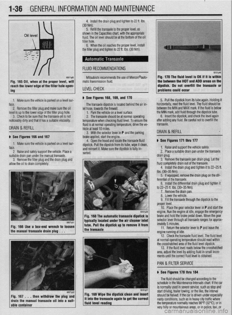
noticeably dirty and that it has a suitable viscosity. u See Figures 168,169, and 170
fluid is at normal operating temperature, drive the ve- The transaxle dipstick is located behind the air in-
hicle at least 10 miles. let hose, towards the firewall.
1. Park the vehicle on a level surface.
2. The transaxle should be at normal operating
temperature when checking fluid level. To ensure the 5. Pull the dipstick from its tube again. Holding it
horizontally, road the fluid level. The fkrid should be
between the MIN and MAX mark. If the fluid is below
the MIN mark, add fluid through the dipstick tube.
DRAIN & REFILL
6. Insert the dipstick, and check the level again
after adding any fluid. Be careful not to overfill the
transaxle.
3. With the selector lever in P and the parking
DRAIN & REFILL u See Figures 166 and 167
1. Make sure the vehicle is parked on a level sur-
face.
2. Raise and safely support the vehicle. Place a brake applied, start the engine.
4. Open the hood and locate the transaxle fluid
dipstick. Pull the dipstick from its tube, wipe it clean,
and reinsert it. Make sure the dipstick is fully in-
serted.
suitable drain pan under the manual transaxle.
3. Remove the filler plug and the drain plug and
allow the oil to drain completely.
Fig. 166 The automatic transaxle dipstick is
typically located under the air cleaner inlet
Fig. 166 Use a box-end wrench to loosen
the manual transaxle drain plug . . . tube. Pull the dipstick up to remove it from
the transaxle
Fig. 169 Wipe the dipstick clean and Insert
/fluid level reading ., it mto the transaxle agam to get the correct
j The fluid should be changed according to the
schedule in the Maintenance Intervals chart. If the car
is normally used in severe service, such as stop and
start driving, trailer towing, or the like, the interval
should be halved. If the car is driven under especially
nasty conditions, such as in heavy city traffic where
the temperature normally reaches 90°F (32%), or in
very hilly or mountainous areas, or in police, taxi, or b See Figures 171 thru 177
1. Raise and support the vehicle safely.
2. Place a suitable drain pan under the transaxle
drain plug.
3. Remove the transaxle pan drain plug. Let the
fluid completely drain out of the transaxle.
4. Install the drain plug and tighten it to 22-25 ft.
lbs. (30-35 Nm).
5. If equipped, remove the drain plug on the dif-
ferential of the transaxle.
6. Install the differential drain plug and tighten ft
to 22-25 ft. Ibs. (30-35 Nm).
7. Remove the drain pan.
8. Lower the vehicle.
9. Fill the transaxle through the dipstick to the
proper level.
10. Place the gear selector lever in P and start the
engine. Run the engine at idle, engage the emergency
brake and hold the brake pedal down. Move the gear
selector lever through all transaxle ranges for approx-
imately 5 minutes.
11. Return the selector lever to P and leave the
engine running at idle.
12. Check the transaxle fluid level. The fluid level
at normal operating temperature should read within
the crosshatched area of the fluid level dipstick.
13. If the fluid level reads below the crosshatched
area, adjust the level by adding fluid in small incre-
ments until the correct fluid level is obtained.
PAN &FILTER SERVICE
b See Figures 178 thru 184
Page 41 of 408
1-42 GENERAL~INFORMATION AND MAINTENANCE
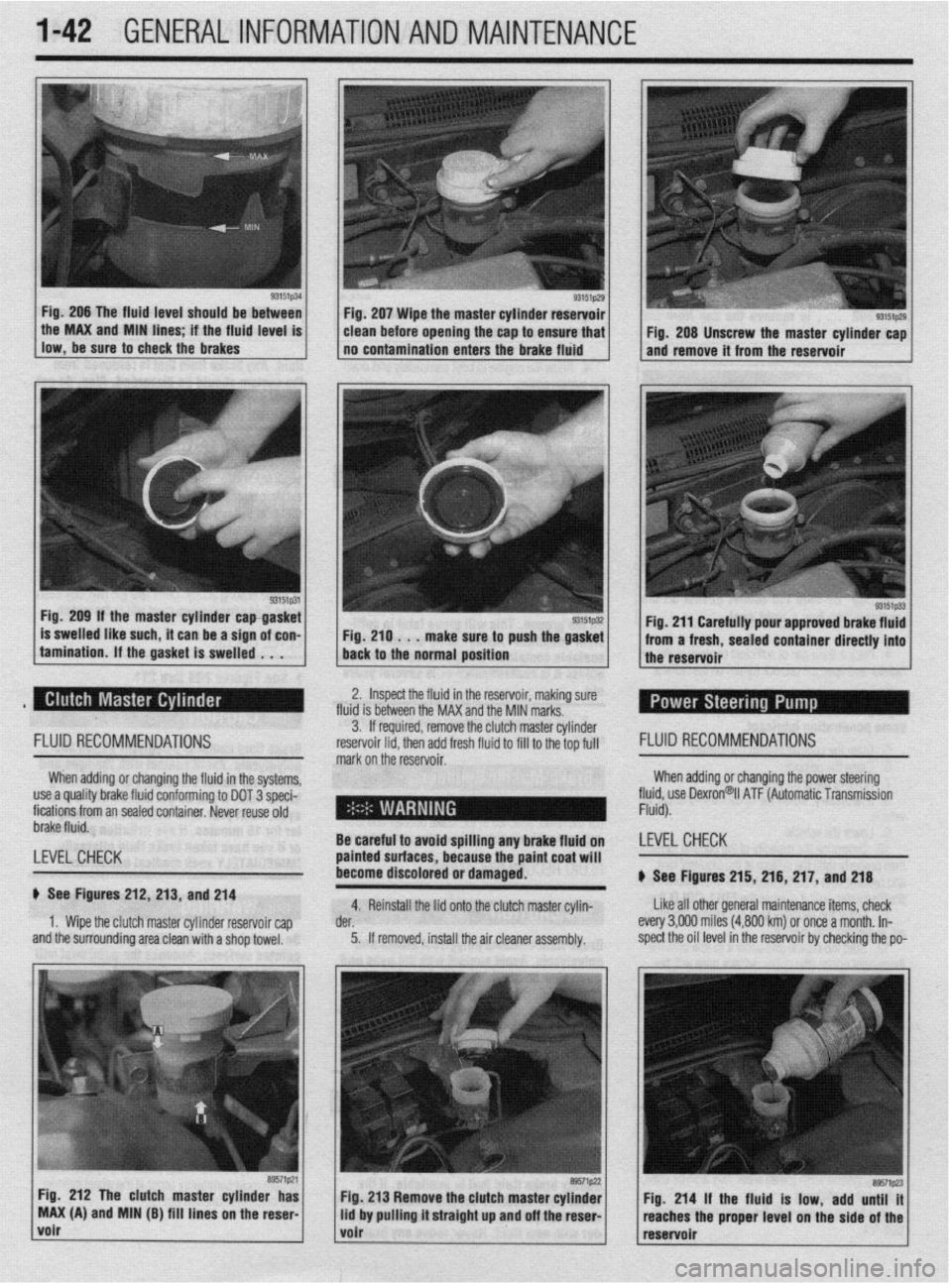
Fig. 206 The fluid level should be between
llow,be*“retoch~ckiebrake~ . the MAX and MIN hnes if the fhud level IS
93151p31 Fig. 209 If the master cylinder capgasket
is swelled like such, it can be a sign of con-
tamination. If the gasket is swelled . . . Fig. 207 Wipe the master cylinder reservoir
clean before opening the cap to ensure that
no contamination enters the brake fluid
Fig. 210 . . .
make sure to push the gasket
back to the normal position
93151p29 I Fig. 208 Unscrew the master cylinder cap
and remove it from the reservoir
Fig. 211 Carefully pour approved brake fluid
from a fresh, sealed container directly into
the reservoir
2. Inspect the fluid in the reservoir, making sure
fluid is between the MAX and the MIN marks.
FLUID RECOMMENDATIONS
When adding or changing the fluid in the systems,
use a quality brake fluid conforming to DOT 3 speci-
fications from an sealed container. Never reuse old
brake fluid.
LEVEL CHECK
b See Figures 212, 213, and 214
1. Wipe the clutch master cylinder reservoir cap
and the surrounding area clean with a shop towel. 3. If required, remove the clut ch master cylinder
reservoir lid. then add fresh fluid I FLUID RECOMMENDATIONS
mark on the’reservoir. to fill to the top full
When adding or changing the power steering
fll$,“” Dexron@il ATF (Automatic Transmission
-
- .
Be careful to avoid sf Billing any brake fluid on LEVELCHECK
painted surfaces, bet
:ause the paint coat will
become discolored or damaged.
b See Figures 215, 216, 217, and 218
4. Reinstall the lid onto the clutch master cylin- Like all other general maintenance items, check
der. every 3,OOfl miles (4,800 km) or once a month. In-
5. If removed, install the air cleaner assembly. spect the oil level in the reservoir by checking the po-
Fig. 212 The clutch master cylinder has
MAX (A) and MIN (B) fill lines on the reser
volr
Page 45 of 408
.
I-46 GENERALINFORMATIONAND MAINTENANCE
2. Pull the jumping vehicle (with the good bat-
tery) into a position so the jumper cables can reach
the dead battery and that vehicle’s engine. Make sure
that the vehicles do NOT touch.
3. Place the transmissions/transaxles of both ve-
hicles in Neutral (MT) or P (AT), as applicable, then
firmly set their parking brakes.
*ff necessary for safety reasons, the hazard
lights on both vehicles may be operated
throughout the entire procedure without sig-
nificantiy increasing the diff icuity of jumping
the dead battery.
4. Turn all lights and accessories OFF on both
vehicles. Make sure the ignition switches on both ve-
hicles are turned to the OFF position.
5. Cover the battery cell caps with a rag, but do
not cover the terminals.
6. Make sure the terminals on both batteries are
clean and free of corrosion or proper electrical con-
nection will be impeded. If necessary, clean the bat-
tery terminals before proceeding.
7. Identify the positive (+) and negative (-) termi-
nals on both batteries.
8. Connect the first jumper cable to the positive
(t) terminal of the dead battery, then connect the
other end of that cable to the positive (t) terminal of
the booster (good) battery.
9. Connect one end of the other jumper cable to
the negative (−) terminal on the booster bat-
tery and the final cable clamp to an engine bolt head,
alternator bracket or other solid, metallic point on the
engine with the dead battery. Try to pick a ground on
the engine that is positioned away from the battery in
order to minimize the possibility of the 2 clamps
touching should one loosen during the procedure.
DO NOT connect this clamp to the negative (-) termi-
nal of the bad battery. cable on the donor battery. Disconnect the positive
cable from the donor battery and finally, disconnect
the positive cable from the formerly dead battery. Be
careful when disconnecting the cables from the posi-
tive terminals not to allow the alligator clips to touch
any metal on either vehicle or a short and sparks will
occur.
I
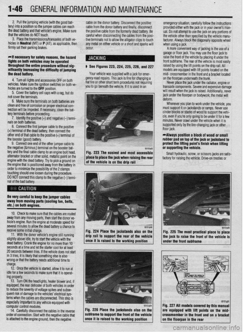
$ See Figures 223,224, 225,226, and 227
Your vehicle was supplied with a jack for emer-
gency road repairs. This jack is fine for changing a
flat tire or other short term procedures not requiring
you to go beneath the vehicle. If it is used in an emergency situation, carefully follow the instructions
provided either with the jack or in your owners man-
ual. Do not attempt to use the jack on any portions of
the vehicle other than specified by the vehicle manu-
facturer. Always block the diagonally opposite wheel
when using a jack.
A more convenient way of jacking is the use of a
garage or floor jack. You may use the floor jack to
raise the front of the vehicle by placing it under the
front subframe. The rear of the vehicle is most easily
raised by using the lift points on the drip rail. All
models are equipped with lift points located on the
mid- crossmember in the front and a bracket located
on the floorpan underneath the trunk.
Never place the jack under the radiator, engine or
transaxle components. Severe and expensive damage
will result when the jack is raised. Additionally, never
jack under the floorpan or
bodywork; the
metal will
Whenever you plan to work under the vehicle, you
must support it on jackstands or ramps. Never use
cinder blocks or stacks of wood to support the vehi-
cle, even if you’re only going to be under it for a few
minutes. Never crawl under the vehicle when it is
supported only by the tire-changing jack or other
*Always position a block of wood or small
rubber pad on top of the jack or jackstand to
protect the lifting point’s finish when lifting
or supporting the vehicle.
Small hydraulic, screw, or scissors jacks are satis-
factory for raising the vehicle. Drive-on trestles or
Be very careful to keep the jumper cables
away from moving parts (cooling fan, belts,
etc.) on both engines.
10. Check to make sure that the cables are routed
away from any moving parts, then start the donor ve-
hicle’s engine. Run the engine at moderate speed for
several minutes to allow the dead battery a chance to
receive some initial charge.
11. With the donor vehicle’s engine still running
slightly above idle, try to start the vehicle with the
dead battery. Crank the engine for no more than 10 &stands also on the
Fig. 225 The most practical place to place
front of the vehicle is
seconds at a time and let the starter cool for at least
20 seconds between tries. If the vehicle does not start
in 3 tries, it is likely thatsomething else is also
wrong or that the battery needs additional time to
charge.
12. Once the vehicle is started, allow it to run at
idle for a few seconds to make sure that it is operat-
ing properly.
13. Turn ON the headlights, heater blower and, if
equipped, the rear defroster of both vehicles in order
to reduce the severity of voltage spikes and subse-
quent risk of damage to the vehicles’ electrical sys-
tems when the cables are disconnected. This step is
especially important to any vehicle equipped with
computer control modules.
14. Carefully disconnect the cables in the’reverse
order of connection. Start with the negative cable that
is attached to the engine ground, then the negative Fig. 226 Place the jackstands also
subframe to support the front of the Fig. 227 All models covered by this
are equipped with lift points on t
crossmember in the front and on a
Page 56 of 408
ENGlNEELECTRldAL 2-9
TESTING
Voltage Test able for use by customers. An alternator
bench test is the most definitive way to de-
termine the condition of your alternator.
REMOVAL&INSTALLATION
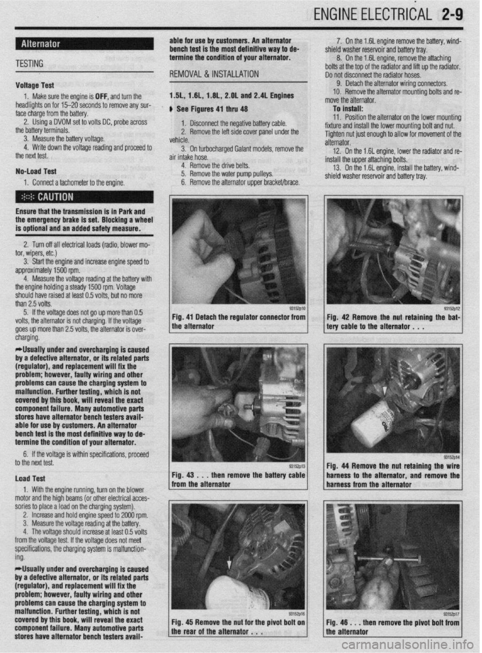
1. Make sure the engine is OFF, and turn the 1.51,1.61, 1.6L, 2.OL and 2.4L Engines
headlights on for 15-20 seconds to remove any sur-
face charge from the battery. , See Figures 4, thru 48
2. Using a DVOM set to volts DC, probe across
1. Disconnect the negative battery cable.
the battery terminals.
3. Measure the battery voltage. 2. Remove the left side cover panel under the
vehicle.
4. Write down the voltage reading and proceed to
3. On turbocharaed Galant models, remove the
the next test.
air intake hose. -
No-load Test
1. Connect a tachometer to the engine. 4. Remove the drive belts.
5. Remove the water pump pulleys.
6. Remove the alternator upper bracket/brace.
Ensure that the transmission
is in Park and the emergency brake is set. Blocking a wheel
is optional and an added safety measure.
2. Turn off all electrical loads (radio, blower mo-
tor, wipers, etc.)
3. Start the engine and increase engine speed to
approximately 1500 rpm.
4. Measure the voltage reading at the battery with
the engine holding a steady 1500 rpm. Voltage
should have raised at least 0.5 volts, but no more
than 2.5 volts.
5. If the voltage does not go up more than 0.5
volts, the alternator is not charging. If the voltage
goes up more than 2.5 volts, the alternator is over-
* 7. On the 1.6L engine remove the battery, wind-
shield washer reservoir and battery tray.
8. On the 1.6L engine, remove the attaching
bolts at the top of the radiator and lift up the radiator.
Do not disconnect the radiator hoses.
9. Detach the alternator wiring connectors.
10. Remove the alternator mounting bolts and re-
move the alternator.
To install:
11. Position the alternator on the lower mountina
fixture and install the lower mounting bolt and nut. U
Tighten nut just enough to allow for movement of the
alternator.
12. On the 1.6L engine, lower the radiator and re-
install the upper attaching bolts.
13. On the 1.6L engine, install the battery, wind-
shield washer reservoir and battery tray.
/ tery cable to the alternator . , . 93152p12 Fig 42 Remove the nut retaining the bat-
cnargmg.
*Usually under and overcharging is‘caused
by a defective alternator, or its related parts
(regulator), and replacement will fix the
problem; however, faulty wiring and other
problems can
cause the charging system to
malfunction. Further testing, which is not
covered by this book, will reveal the exact
component failure. Many automotive parts
stores have alternator bench testers avaii-
able for use by customers. An alternator
bench test is the most definitive way to de-
termine the condition of your alternator.
6. If the voltage is within specifications, proceeU
to the next test.
Load Test
1. With the engine running, turn on the blower
motor and the hioh beams (or other electrical acces-
sories to place aioad on the charging system). Fig. 44 Remove the nut retaining the
then remove the batte harness to the alternator and remov
,
2. Increase and hold engine speed to 2000 rpm.
3. Measure the voltage reading at the battery.
4. The voltage should increase at least 0.5 volts
from the voltage test. If the voltage does not meet
specifications, the charging system is malfunction-
ing.
*Usually under and overcharging is caused
by a defective alternator, or its related parts
(regulator), and replacement will fix the
problem; however, faulty wiring and other
problems can cause the charging system to
malfunction. Further testing, which is not
covered by this book, will reveal the exact
component failure. Many automotive parts
stores have alternator bench testers avaii-
93152p17 en remove the pivot bolt from
Page 58 of 408
ENGINE ELECTRICAL 2-11
l.unVeMlil(GSflWtWJ
2.Gwwator harness con- connectk,,,
3. Engme OS, level d,pst,&
4 Generator
Fig. 51 Alternator mounting -3.51 engine
The starting system includes the battery, starter
motor, solenoid, ignition switch, circuit protection
and wiring connecting the components. An inhibitor
switch located in the park/neutral safety switch or
Transmission Range (TR) sensor is included in the
starting system to prevent the vehicle from being
started with the vehicle in gear.
When the ignition key is turned to the START po-
sition, current flows and energizes the starters sole-
noid coil. The solenoid plunger and clutch shift lever
are activated and the clutch pinion engages the ring
gear on the flywheel. The switch contacts close and
the starter cranks the engine until it starts.
To prevent damage caused by excessive starter ar-
mature rotation when the engine starts, the starter in-
corporates an over-running clutch in the pinion gear. 2. Connect a voltmeter between the positive ter-
minal of the battery and the starter B+ circuit.
3. Turn the ignition key to the START position
and note the voltage on the meter.
4. If voltage reads 0.5 volts or more, there is high
resistance in the starter cables or the cable ground,
repair as necessary. If the voltage reading is ok pro-
teed to the next step.
5. Connect a voltmeter between the positive ter-
minal of the battery and the starter M circuit,
6. Turn the ignition key to the START position
and note the voltage on the meter.
7. If voltage reads 0.5 volts or more, there is high
resistance in the starter. Repair or replace the starter
as necessary.
*Many automotive parts stores have starter
bench testers available for use by customers.
A starter bench test is the most definitive
way to determine the condition of your
starter. 3. Remove the resonator retaining nuts and re-
move the air intake hose and resonator assembly as
required.
rllse care when removing the air cleaner
cover because the air-flow sensor is attached
and is a sensitive component.
4. If equipped with Active-ECS suspension, re-
move the air compressor as follows:
a. Detach the two electrical connectors, from
the compressor.
b. Disconnect the air line at the compressor.
c. Remove the three mounting bolts, securing
the compressor to the chassis.
5. Raise the vehicle and support safely.
6. Remove the engine undercover.
7. Remove the heat shield from beneath the in-
take manifold on the 1.5L engine.
8. If necessary, detach the speedometer cable
connector at the transaxle end.
9. Detach the starter motor electrical connac-
TESTING
Voltage Drop Test
*The battery must be in good condition and
fully charged prior to performing this test. REMOVAL&INSTALLATION
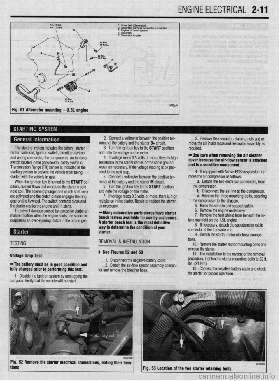
# See Figures 52 and 53
1. Disconnect the negative battery cable.
2. Detach the air-flow sensor assembly connec-
tor and remove the breather hose.
1. Disable the ignition system by unplugging the
coil pack. Verify that the vehicle will not start. tions.
10. Remove the starter motor mounting bolts and
remove the starter.
11. The installation is the reverse of the removal
procedure. Tighten the starter mounting bolts to 22 ft.
Ibs. (31 Nm).
12. Connect the negative battery cable and check
the starter for proper operation.
9315zp19 Fig. 53 Location of the two starter retaining bolts
Page 126 of 408
I)
ENGINEANDENGINEOVERHAUL 3-65
10. Install the camshaft(s), rockers, shafts and
any other components that were removed for disas-
sembly.
GENERAL INFORMATION ways number 1. However, depending on the engine
placement, the front of the engine could either be the
flywheel or damper/pulley end. Generally the front of
the engine faces the front of the vehicle. Use a num-
ber punch or scribe and also mark the main bearing
caps from front to rear with the front most cap being
number 1 (if there are five caps, mark them 1 through
5, front to rear).
A thorough overhaul or rebuild of an engine block
would include replacing the pistons, rings, bearings,
timing belt/chain assembly and oil pump. For OHV
engines also include a new camshaft and lifters. The
block would then have the cylinders bored and honed
oversize (or if using removable cylinder sleeves, new
sleeves installed) and the crankshaft would be cut
undersize to provide new wearing surfaces and per-
feet clearances. However, your particular engine may Take special care when pushing the connect-
ing rod up from the crankshaft because the
sharp threads of the rod bolts/studs will
score the crankshaft journal. Insure that spe-
cial plastic caps are installed over them, or
cut two pieces of rubber hose to do the
same.
Again, rotate the engine, this time to position the
number one cylinder bore (head surface) up. Turn the
crankshaft until the number one piston is at the bot-
tom of its travel, this should allow the maximum ac-
cess to its connecting rod. Remove the number one
connecting rods fasteners and cap and place two
lengths of rubber hose over the rod bolts/studs to
protect the crankshaft from damage. Using a sturdy
wooden dowel and a hammer, push the connecting
rod up about 1 in. (25mm) from the crankshaft and
remove the upper bearing insert. Continue pushing
or tapping the connecting rod up until the piston
rings are out of the cylinder bore. Remove the piston
and rod by hand, put the upper half of the bearing in-
sert back into the rod, install the cap with its bearing
insert installed, and hand-tighten the cap fasteners. If
the parts are kept in order in this manner, they will
not get lost and you will be able to tell which bear-
ings came form what cylinder if any problems are
discovered and diagnosis is necessary. Remove all
the other piston assemblies in the same manner. On
V-style engines, remove all of the pistons from one
bank, then reposition the engine with the other cylin-
der bank head surface up, and remove that banks nis-
prevent the assemblies from being removed,
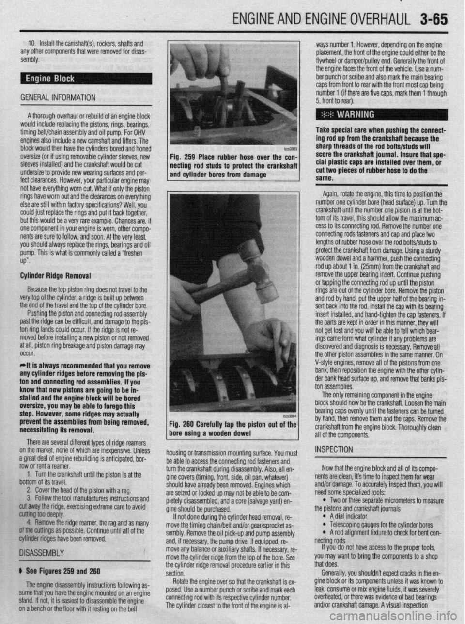
necessitating its removal. Fig. 260 Carefully tap the piston out of the
bore using a wooden dowel
There are several different types of ridge reamers
on the market, none of which are inexpensive, Unless
.3 “me.+ ,-ins, rdnnn;nn mh~lil.-linn ;I nn+:n:nnL.* l.^W
a ylwx “Gal “I cllylllc Ir;““ll”llly 13 dllLILlpxC”, ““I- row or rent a reamer.
1. Turn the crankshaft until the piston is at the
bottom of its travel.
2. Cover the head of the piston with a rag.
3. Follow the tool manufacturers instructions and housing or transmission mounting surface. You must
1 as many
II of the
~1SA~E~BLY
b See Figures 259 and 260
The engine disassembly instructions following as-
sume that you have the engine mounted on an engine
stand. If not, it is easiest to disassemble the engine
on a bench or the floor with it resting on the bell be able to access the connecting rod fasteners and
turn the crankshaft during disassembly. Also, all en-
gine covers (timing, front, side, oil pan, whatever)
should
are sei2
nletelv have already been removed. Engines which
,ed or locked up may not be able to be com-
r’-‘-‘, disassembled, and a core (salvage yard) en-
gine sh ould be purchased.
If no
t done during the cylinder head removal, re-
move the timing chain/belt and/or gear/sprocket as-
sembly. Remove the oil pick-up and pump assembly
and, if necessary, the pump drive. If equipped, re-
move any balance or auxiliary shafts. If necessary, re-
move the cylinder ridge from the top of the bore. See
the cylinder ridge removal procedure earlier in this
section.
Rotate the engine over so that the crankshaft is ex-
posed. Use a number punch or scribe and mark each
connecting rod with its respective cylinder number.
The cylinder closest to the front of the engine is al- cut away the ridge, exercising extreme care to avoid
~ ioo deepfy.
4. Remove the ridge reamer, the rag and
armings as possible. Continue until a
biter ridges have been removed. ton assemblies.
The only remaining component in the engine
block should now be the crankshaft. Loosen the main
bearing caps evenly until the fasteners can be turned
by hand, then remove them and the caps. Remove the
crankshaft from the engine block. Thoroughly clean
all of the components.
INSPECTION
Now that the engine block and all of its compo-
nents are clean, it’s time to inspect them for wear
and/or damage. To accurately inspect them, you will
need some specialized tools:
l Two or three separate micrometers to measure
the prstons and crankshaft journals
l A dial indicator l Telescoping gauges for the cylinder bores l A rod alignment fixture to check for bent con-
netting rods
If you do not have access to the proper tools,
you may want to bring the components to a shop
that does.
Generally, you shouldn’t expect cracks in the en-
gine block or its components unless it was known to
leak, consume or mix engine fluids, it was severely
overheated, or there was evidence of bad bearings
and/or crankshaft damage. A visual inspection
Page 170 of 408
DRIVEABILITYAND EMISSIONS CONTROLS 4-27
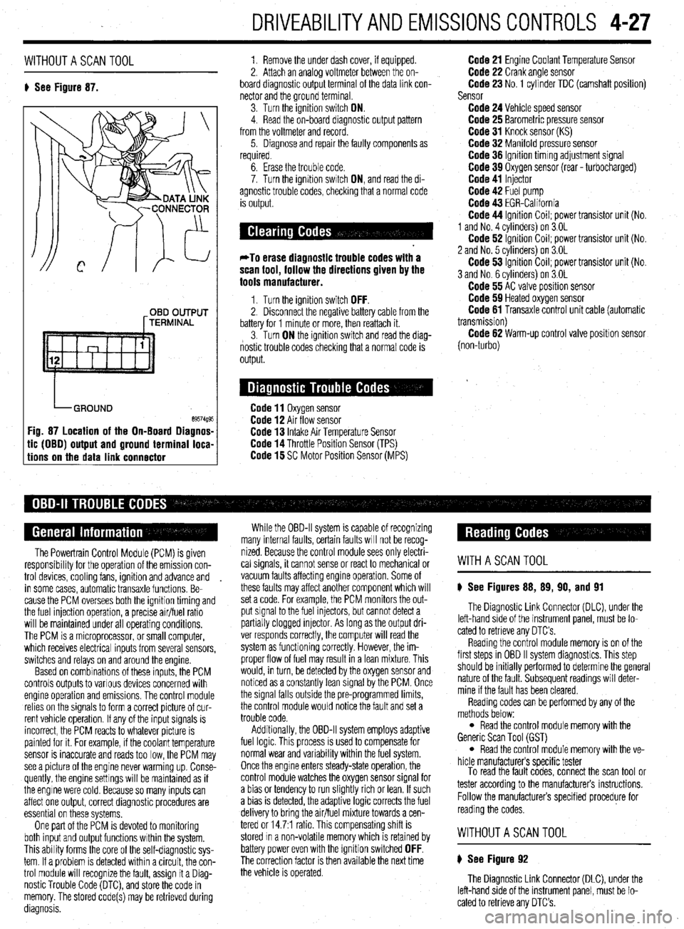
WITHOUTASCANTOOL
8 See Figure 87. 1. Remove the under dash cover, if equipped.
2. Attach an analoa voltmeter between the on-
board diagnostic outpit terminal of the data link con-
nector and the ground terminal
3. Turn the ignition switch ON.
4. Read the on-board diagnostic output pattern
from the voltmeter and record.
5. Diagnose and repair the faulty components as
required.
OBD OUTPUT
[TERMINAL
tic (OBO) output and ground terminal loca-
tions on the data link connector
6. Erase the trouble code.
7. Turn the ignition swatch ON, and read the di-
agnostic trouble codes, checking that a normal code
is output.
*To erase diagnostic trouble codes with a
scan tool, follow the directions given by the
tools manufacturer.
1. Turn the ignition switch OFF. 2. Disconnect the negative battery cable from the
battery for 1 minute or more, then reattach it.
3. Turn ON the ignition switch and read the diag-
nostic trouble codes checking that a normal code is
output.
Code 11 Oxygen sensor Code 12 Air flow sensor Code 13 Intake Air Temperature Sensor Code 14 Throttle Position Sensor (TPS) Code 15 SC Motor Position Sensor (MPS)
Code 21 Engine Coolant Temperature Sensor Code 22 Crank angle sensor Code 23 No. 1 cylinder TDC (camshaft position)
Sensor
Code 24 Vehicle speed sensor Code 25 Barometric pressure sensor Code 31 Knock sensor (KS) Code 32 Manifold pressure sensor Code 36 Ignition timmg adjustment signal Code 39 Oxygen sensor (rear - turbocharged) Code 41 Injector Code 42 Fuel pump Code 43 EGR-California Code 44 Ignition Coil; power transistor unit (No.
1 and No. 4 cvlinders) on 3.OL
Code 62 ignition Coil; power transistor unit (No.
2 and No. 5 cvlinders) on 3.OL
Code 53 ignition Coil; power transistor unit (No.
3 and No. 6 cylinders) on 3.OL
Code 55 AC valve position sensor Code 59 Heated oxygen sensor Code 61 Transaxle control unit cable (automatic
transmission)
Code 62 Warm-up control valve position sensor
(non-turbo)
The Powertrain Control Module (PCM) is given
responsibrlity for the operation of the emission con-
trol devices, cooling fans, ignition and advance and
in some cases, automatic transaxle functions. Be-
cause the PCM oversees both the ignition timing and
the fuel injection operation, a precise air/fuel ratio
will be maintained under all operating conditions,
The PCM is a microprocessor, or small computer,
which receives electrical inputs from several sensors,
switches and relays on and around the engine.
Based on combinations of these inputs, the PCM
controls outputs to various devices concerned with
engine operation and emissions. The control module
relies on the signals to form a correct picture of cur-
rent vehicle operation. If any of the input signals is
incorrect, the PCM reacts to whatever picture is
painted for it. For example, if the coolant temperature
sensor is inaccurate and reads too low, the PCM may
see a picture of the engine never warming up. Conse-
quently, the engine settings will be maintained as if
the engine were cold. Because so many inputs can
affect one output, correct diagnostic procedures are
essential on these systems,
One part of the PCM is devoted to monitoring
both input and output functions within the system.
This ability forms the core of the self-diagnostic sys-
tem. If a problem is detected within a circuit, the con-
trol module will recognize the fault, assign it a Diag-
nostic Trouble Code (DTC), and store the code in
memory. The stored code(s) may be retrieved during
diagnosis. While the OBD-II system is capable of recognizing
many internal faults, certain faults WIII not be recog-
nized. Because the control module sees only electri-
cal signals, it cannot sense or react to mechanical or
vacuum faults affecting engine operation. Some of
these faults may affect another component which will
set a code. For example, the PCM monitors the out-
put signal to the fuel injectors, but cannot detect a
partially clogged injector. As long as the output dri-
ver responds correctly, the computer will read the
system as functioning correctly. However, the im-
proper flow of fuel may result in a lean mixture. This
would, in turn, be detected by the oxygen sensor and
noticed as a constantly lean signal by the PCM. Once
the signal falls outside the pre-programmed limits,
the control module would notice the fault and set a
trouble code.
Additionally, the OBD-II system employs adaptive
fuel logic. This process is used to compensate for
normal wear and variability within the fuel system.
Once the engine enters steady-state operation, the
control module watches the oxygen sensor signal for
a bias or tendency to run slightly rich or lean. If such
a bias is detected, the adaptive logic corrects the fuel
delivery to bring the air/fuel mixture towards a cen-
tered or 14.7:1 ratio. This compensating shift is
stored In a non-volatile memory which is retained by
battery power even with the ignition switched
OFF. The correction factor is then available the next time
the vehicle is operated.
WITHASCANTOOL
8 See Figures 88, 89, 90, and 91
The Diagnostic Link Connector (DLC), under the
left-hand side of the instrument panel, must be lo-
cated to retrieve any OTC’s
Reading the control module memory is on of the
first steps in OBD II system diagnostics. This step
should be initially performed to determine the general
nature of the fault. Subsequent readings will deter-
mine if the fault has been cleared.
Reading codes can be performed by any of the
methods below:
l Read the control module memory with the
Generic Scan Tool (GST)
l Read the control module memory with the ve-
hicle manufacturers specific tester
To read the fault codes, connect the scan tool or
tester according to the manufacturers instructions.
Follow the manufacturers specified procedure for
reading the codes.
WITHOUTASCANTOOL
8 See Figure 92
The Diagnostic Link Connector (DLC), under the
left-hand side of the instrument panel, must be lo-
cated to retrieve any DTC’s.