2024 FORD F650/750 warning light
[x] Cancel search: warning lightPage 187 of 386
ESSENTIAL TOWING CHECKS
See Load limits in the Load Carryingchapter for load specification terms foundon the tire label and Safety Compliancelabel and instructions on calculating yourvehicle's load.
Remember to account for the trailertongue weight as part of your vehicle loadwhen calculating the total vehicle weight.
Hitches
Do not use a hitch that either clamps ontothe bumper or attaches to the axle. Youmust distribute the load in your trailer sothat 10-15% of the total weight of thetrailer is on the tongue.
Safety Chains
Note:Do not attach safety chains to thebumper.
Always connect the safety chains to theframe or hook retainers of your vehiclehitch.
To connect the safety chains, cross thechains under the trailer tongue and allowenough slack for turning tight corners. Donot allow the chains to drag on the ground.
Trailer Brakes
WARNING: Do not connect atrailer's hydraulic brake system directlyto your vehicle's brake system. Yourvehicle may not have enough brakingpower and your chances of having acollision greatly increase.
Electric brakes and manual, automatic orsurge-type trailer brakes are safe if youinstall them properly and adjust them tothe manufacturer's specifications. Thetrailer brakes must meet local and federalregulations.
The rating for the tow vehicle's brakingsystem operation is at the gross vehicleweight rating, not the gross combinedweight rating.
Trailer Lamps
WARNING: Never connect anytrailer lamp wiring to the vehicle's taillamp wiring; this may damage theelectrical system resulting in fire. Contactyour authorized dealer as soon aspossible for assistance in proper trailertow wiring installation. Additionalelectrical equipment may be required.
Trailer lamps are required on most towedvehicles. Make sure all running lights, brakelights, turn signals and hazard lights areworking.
Before Towing a Trailer
Practice turning, stopping and backing upto get the feel of your vehicle-trailercombination before starting on a trip.When turning, make wider turns so thetrailer wheels clear curbs and otherobstacles.
When Towing a Trailer
•Check your hitch, electrical connectionsand trailer wheel lug nuts thoroughlyafter you have traveled 50 mph(80 km/h).
•When stopped in congested or heavytraffic during hot weather, place thetransmission in park (P) or neutral (N)to aid engine and transmission coolingand to help air conditioningperformance.
•Turn off the speed control with heavyloads or in hilly terrain. The speedcontrol may turn off automaticallywhen you are towing on long, steepgrades.
183
2024 F-650/750 (TBC) , enUSA, Edition date: 202210, First-PrintingTowing
Page 188 of 386
•Shift to a lower gear when driving downa long or steep hill. Do not apply thebrakes continuously, as they mayoverheat and become less effective.
•If your transmission is equipped withthe Tow/Haul feature, use this featurewhen towing. This provides enginebraking and helps eliminate excessivetransmission shifting for optimum fueleconomy and transmission cooling.
•Allow more distance for stopping witha trailer attached. Anticipate stops andbrake gradually.
FIFTH WHEEL OPERATION (IF
EQUIPPED)
WARNING: Failure to follow thefifth wheel manufacturer’s instructionsfor hooking and unhooking as well assliding the fifth wheel could result in anaccident, personal injury or death.
WARNING: When the tractor andtrailer are parked unattended, the trailerbrake hand control should never be usedto apply the brake, since air may leakfrom the system, allowing vehiclemovement, resulting in possible propertydamage, personal injury or death.
Before hook-up, make sure:
•The fifth wheel jaws are fully open.
•The fifth wheel is fully tilted back toprevent body damage when the tractoris backed under a trailer.
•You block the trailer wheels and adjustand apply the trailer spring brakes.Never chase a trailer.
•The brake hoses and light cords areclear of the fifth wheel.
Hook-up
1.Back the tractor squarely under thetrailer, engaging the fifth-wheel jawson the kingpin. Always back up slowly;make sure the trailer is neither too highnor too low. Avoid backing under thetrailer from an angle.
2.Connect the service and emergencybrake hoses and trailer light connector.
3.Inspect the jaws of the fifth wheel tobe sure they have fully closed on thetrailer kingpin and the trailer plate isresting securely on the fifth wheel.
4.Make sure the coupler release lever isin the locked position.
5.Charge the trailer brake system. Setthe trailer brakes, with either the handvalve or tractor protection valve. Pullagainst the trailer for an extra check ofproper hook-up. Do not pull hardenough to damage or strain theequipment.
6.Set the tractor parking brakes and fullyraise the trailer landing gear.
7.Check the operation of all trailer lightsand correct any lights that may befaulty.
Un-hook
1.Try to keep the tractor and trailer in astraight line.
2.Apply the parking brakes.
3.Lower the trailer landing gear, makingsure it is on solid, level ground. Theweight of the trailer is to be on thelanding gear.
4.Block the trailer wheels.
5.Disconnect the brake hoses and lightcords. Be sure hoses and cords areclear.
6.Pull coupler release lever to disengagethe fifth wheel jaws.
184
2024 F-650/750 (TBC) , enUSA, Edition date: 202210, First-PrintingTowing
Page 193 of 386
DRIVING THROUGH WATER
WARNING: Do not drive throughflowing or deep water as you may losecontrol of your vehicle.
Note:Driving through standing water cancause vehicle damage.
Note:Engine damage can occur if waterenters the air filter.
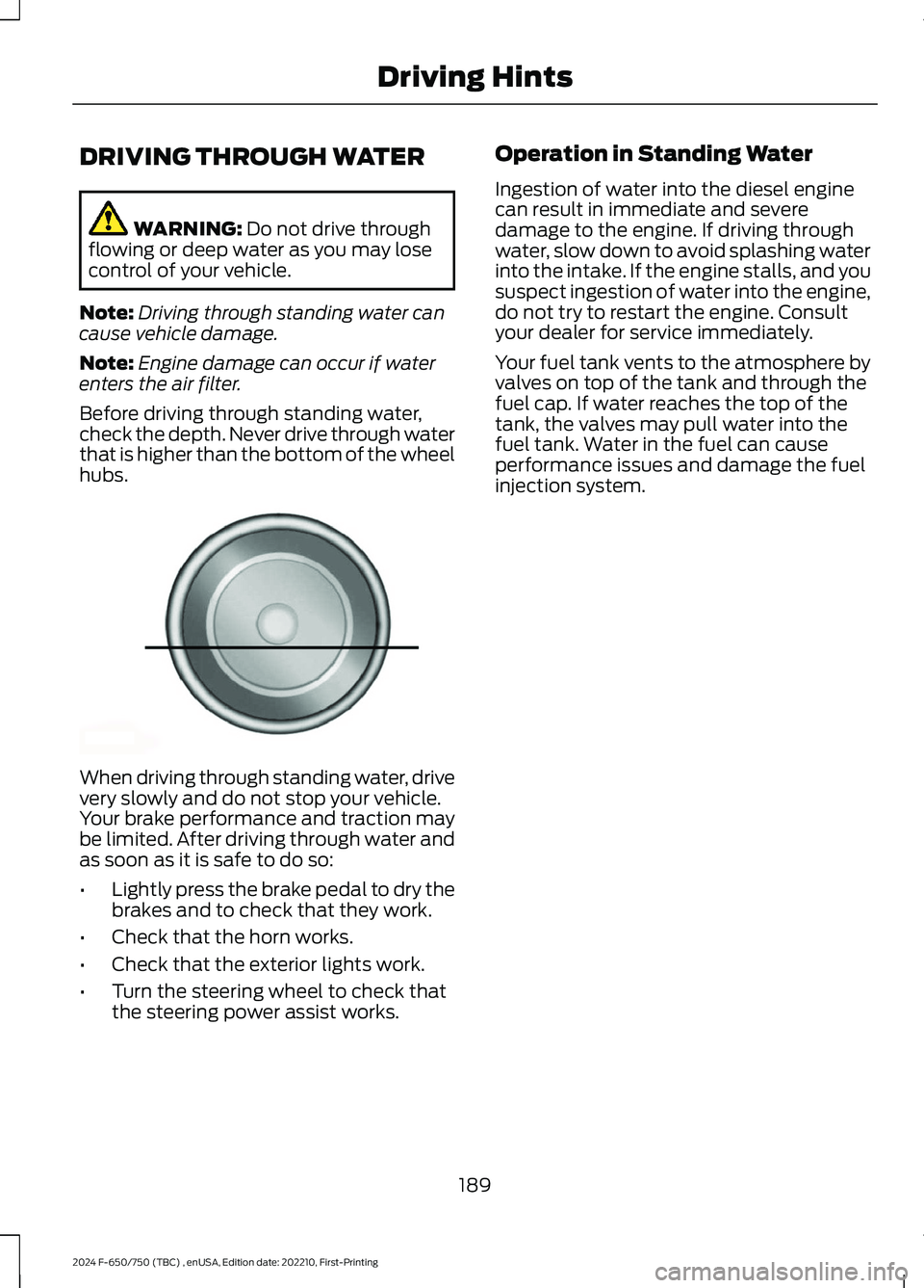
Before driving through standing water,check the depth. Never drive through waterthat is higher than the bottom of the wheelhubs.
When driving through standing water, drivevery slowly and do not stop your vehicle.Your brake performance and traction maybe limited. After driving through water andas soon as it is safe to do so:
•Lightly press the brake pedal to dry thebrakes and to check that they work.
•Check that the horn works.
•Check that the exterior lights work.
•Turn the steering wheel to check thatthe steering power assist works.
Operation in Standing Water
Ingestion of water into the diesel enginecan result in immediate and severedamage to the engine. If driving throughwater, slow down to avoid splashing waterinto the intake. If the engine stalls, and yoususpect ingestion of water into the engine,do not try to restart the engine. Consultyour dealer for service immediately.
Your fuel tank vents to the atmosphere byvalves on top of the tank and through thefuel cap. If water reaches the top of thetank, the valves may pull water into thefuel tank. Water in the fuel can causeperformance issues and damage the fuelinjection system.
189
2024 F-650/750 (TBC) , enUSA, Edition date: 202210, First-PrintingDriving HintsE176913
Page 194 of 386
HAZARD FLASHERS
Note:If used when the vehicle is notrunning, the battery loses charge. As a result,there may be insufficient power to restartyour vehicle.
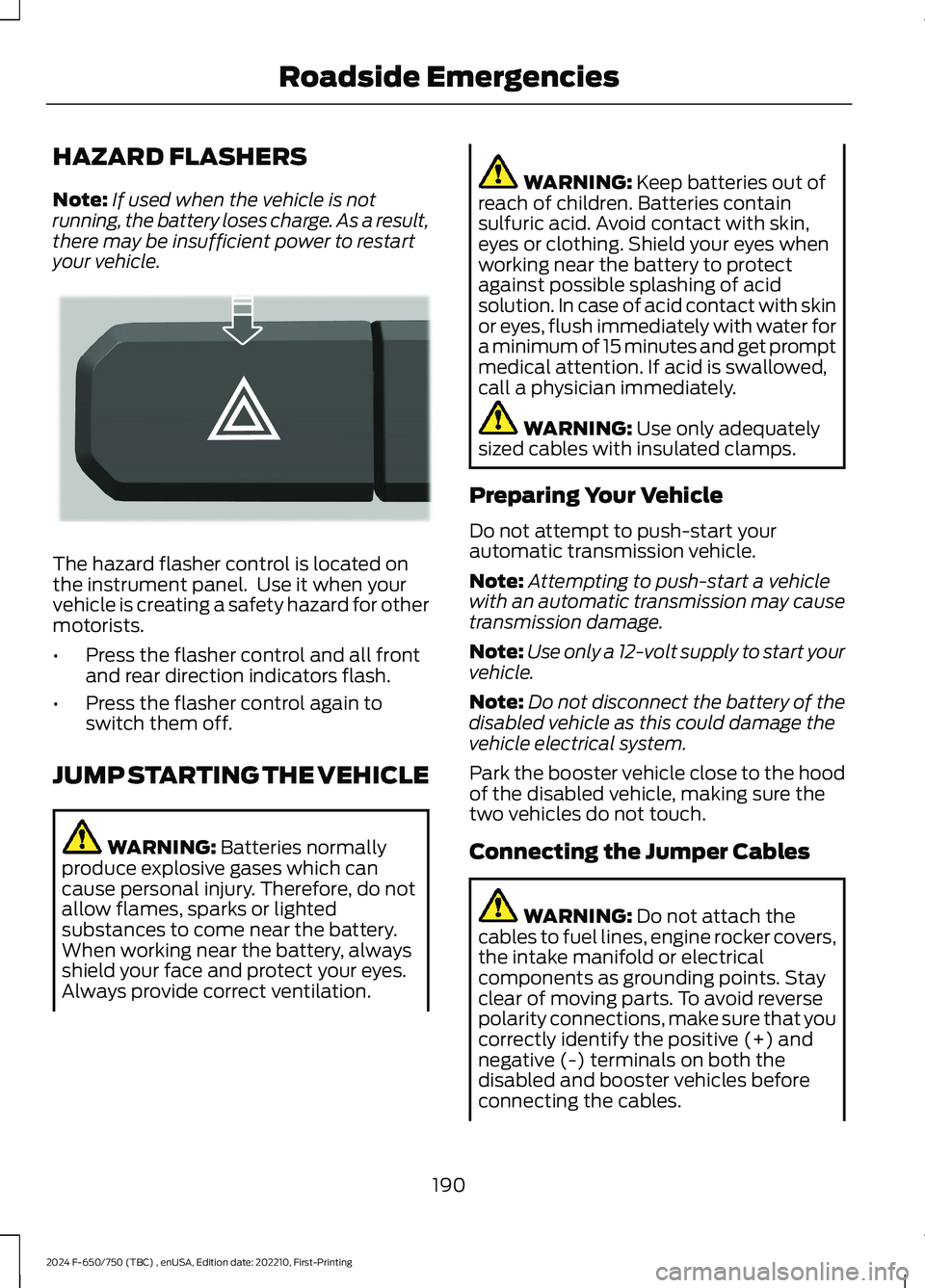
The hazard flasher control is located onthe instrument panel. Use it when yourvehicle is creating a safety hazard for othermotorists.
•Press the flasher control and all frontand rear direction indicators flash.
•Press the flasher control again toswitch them off.
JUMP STARTING THE VEHICLE
WARNING: Batteries normallyproduce explosive gases which cancause personal injury. Therefore, do notallow flames, sparks or lightedsubstances to come near the battery.When working near the battery, alwaysshield your face and protect your eyes.Always provide correct ventilation.
WARNING: Keep batteries out ofreach of children. Batteries containsulfuric acid. Avoid contact with skin,eyes or clothing. Shield your eyes whenworking near the battery to protectagainst possible splashing of acidsolution. In case of acid contact with skinor eyes, flush immediately with water fora minimum of 15 minutes and get promptmedical attention. If acid is swallowed,call a physician immediately.
WARNING: Use only adequatelysized cables with insulated clamps.
Preparing Your Vehicle
Do not attempt to push-start yourautomatic transmission vehicle.
Note:Attempting to push-start a vehiclewith an automatic transmission may causetransmission damage.
Note:Use only a 12-volt supply to start yourvehicle.
Note:Do not disconnect the battery of thedisabled vehicle as this could damage thevehicle electrical system.
Park the booster vehicle close to the hoodof the disabled vehicle, making sure thetwo vehicles do not touch.
Connecting the Jumper Cables
WARNING: Do not attach thecables to fuel lines, engine rocker covers,the intake manifold or electricalcomponents as grounding points. Stayclear of moving parts. To avoid reversepolarity connections, make sure that youcorrectly identify the positive (+) andnegative (-) terminals on both thedisabled and booster vehicles beforeconnecting the cables.
190
2024 F-650/750 (TBC) , enUSA, Edition date: 202210, First-PrintingRoadside EmergenciesE304635
Page 218 of 386
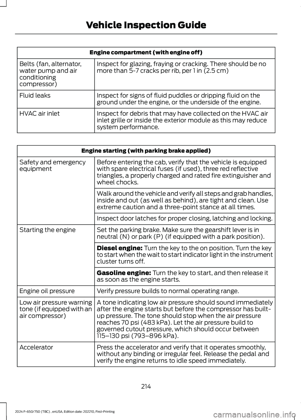
Engine compartment (with engine off)
Inspect for glazing, fraying or cracking. There should be nomore than 5-7 cracks per rib, per 1 in (2.5 cm)Belts (fan, alternator,water pump and airconditioningcompressor)
Inspect for signs of fluid puddles or dripping fluid on theground under the engine, or the underside of the engine.Fluid leaks
Inspect for debris that may have collected on the HVAC airinlet grille or inside the exterior module as this may reducesystem performance.
HVAC air inlet
Engine starting (with parking brake applied)
Before entering the cab, verify that the vehicle is equippedwith spare electrical fuses (if used), three red reflectivetriangles, a properly charged and rated fire extinguisher andwheel chocks.
Safety and emergencyequipment
Walk around the vehicle and verify all steps and grab handles,inside and out (as well as behind), are tight and clean. Useextreme caution and a three-point stance at all times.
Inspect door latches for proper closing, latching and locking.
Set the parking brake. Make sure the gearshift lever is inneutral (N) or park (P) (if equipped with a park position).Starting the engine
Diesel engine: Turn the key to the on position. Turn the keyto start when the wait to start indicator light in the instrumentcluster turns off.
Gasoline engine: Turn the key to start, and then release itas soon as the engine starts.
Verify pressure builds to normal operating range.Engine oil pressure
A tone indicating low air pressure should sound immediatelyafter the engine starts but before the compressor has built-up pressure. The tone should stop when the air pressurereaches 70 psi (483 kPa). Let the air pressure build togoverned cutout pressure, which should occur between115–130 psi (793–896 kPa).
Low air pressure warningtone (if equipped with anair compressor)
Press the accelerator and verify that it operates smoothly,without any binding or irregular feel. Release the pedal andverify the engine returns to idle speed immediately.
Accelerator
214
2024 F-650/750 (TBC) , enUSA, Edition date: 202210, First-PrintingVehicle Inspection Guide
Page 219 of 386
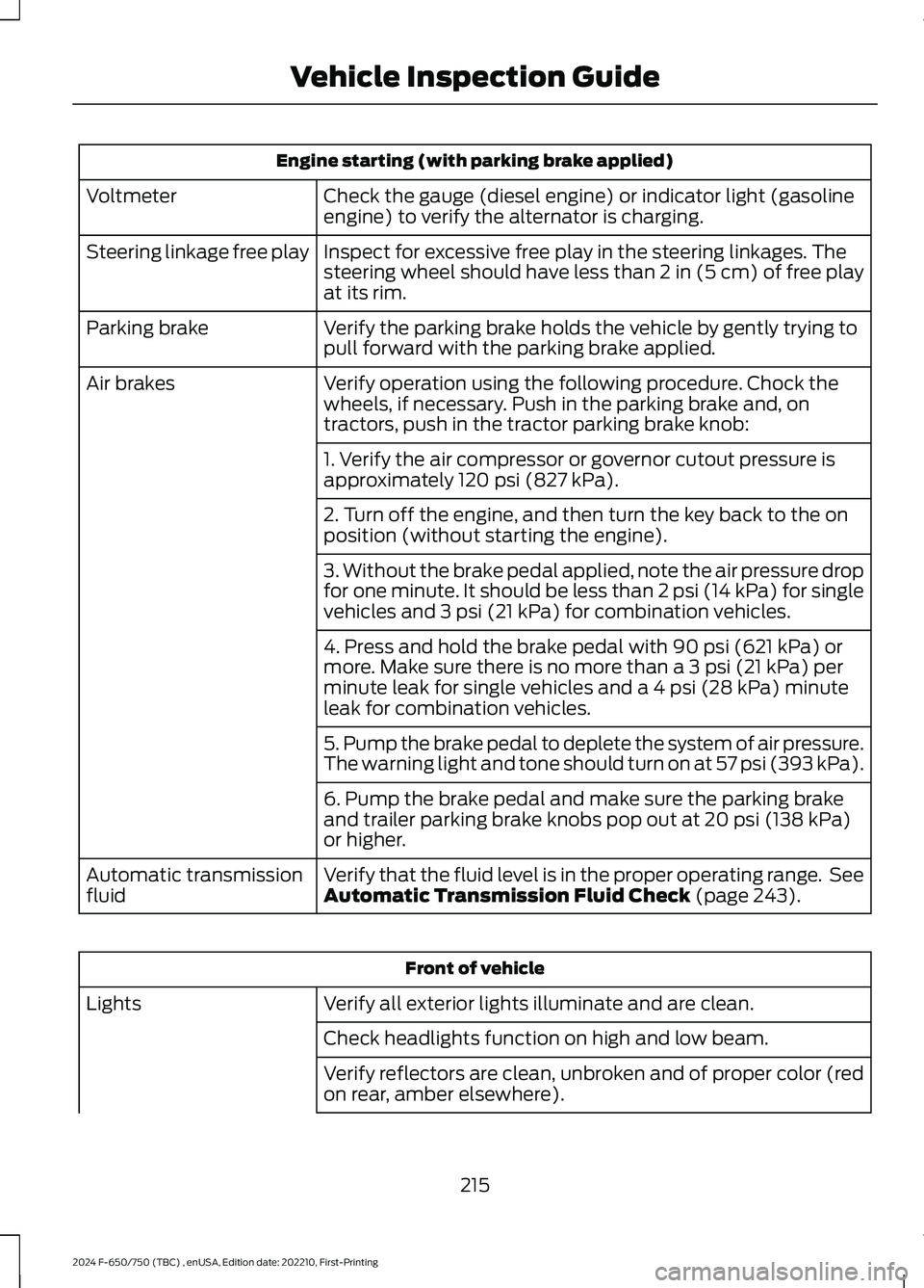
Engine starting (with parking brake applied)
Check the gauge (diesel engine) or indicator light (gasolineengine) to verify the alternator is charging.Voltmeter
Inspect for excessive free play in the steering linkages. Thesteering wheel should have less than 2 in (5 cm) of free playat its rim.
Steering linkage free play
Verify the parking brake holds the vehicle by gently trying topull forward with the parking brake applied.Parking brake
Verify operation using the following procedure. Chock thewheels, if necessary. Push in the parking brake and, ontractors, push in the tractor parking brake knob:
Air brakes
1. Verify the air compressor or governor cutout pressure isapproximately 120 psi (827 kPa).
2. Turn off the engine, and then turn the key back to the onposition (without starting the engine).
3. Without the brake pedal applied, note the air pressure dropfor one minute. It should be less than 2 psi (14 kPa) for singlevehicles and 3 psi (21 kPa) for combination vehicles.
4. Press and hold the brake pedal with 90 psi (621 kPa) ormore. Make sure there is no more than a 3 psi (21 kPa) perminute leak for single vehicles and a 4 psi (28 kPa) minuteleak for combination vehicles.
5. Pump the brake pedal to deplete the system of air pressure.The warning light and tone should turn on at 57 psi (393 kPa).
6. Pump the brake pedal and make sure the parking brakeand trailer parking brake knobs pop out at 20 psi (138 kPa)or higher.
Verify that the fluid level is in the proper operating range. SeeAutomatic Transmission Fluid Check (page 243).Automatic transmissionfluid
Front of vehicle
Verify all exterior lights illuminate and are clean.Lights
Check headlights function on high and low beam.
Verify reflectors are clean, unbroken and of proper color (redon rear, amber elsewhere).
215
2024 F-650/750 (TBC) , enUSA, Edition date: 202210, First-PrintingVehicle Inspection Guide
Page 224 of 386
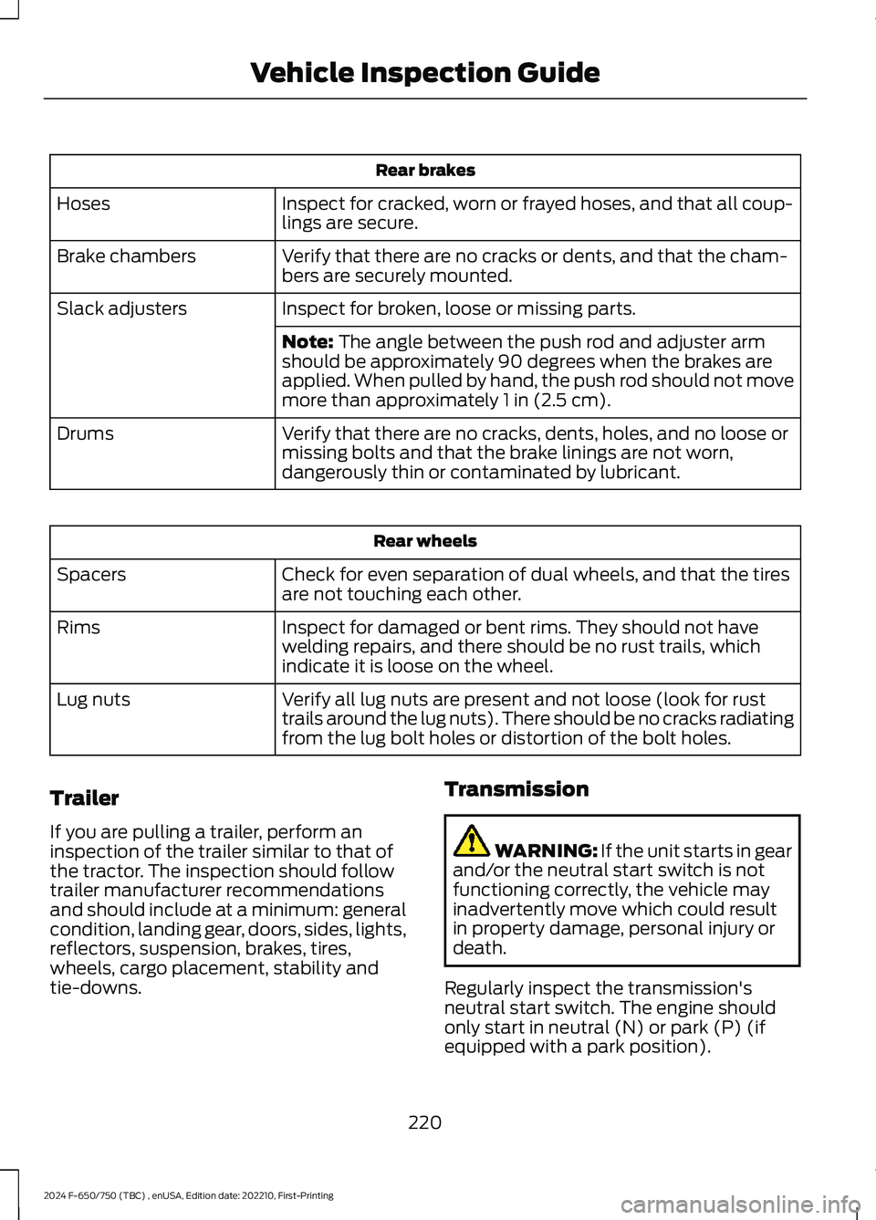
Rear brakes
Inspect for cracked, worn or frayed hoses, and that all coup-lings are secure.Hoses
Verify that there are no cracks or dents, and that the cham-bers are securely mounted.Brake chambers
Inspect for broken, loose or missing parts.Slack adjusters
Note: The angle between the push rod and adjuster armshould be approximately 90 degrees when the brakes areapplied. When pulled by hand, the push rod should not movemore than approximately 1 in (2.5 cm).
Verify that there are no cracks, dents, holes, and no loose ormissing bolts and that the brake linings are not worn,dangerously thin or contaminated by lubricant.
Drums
Rear wheels
Check for even separation of dual wheels, and that the tiresare not touching each other.Spacers
Inspect for damaged or bent rims. They should not havewelding repairs, and there should be no rust trails, whichindicate it is loose on the wheel.
Rims
Verify all lug nuts are present and not loose (look for rusttrails around the lug nuts). There should be no cracks radiatingfrom the lug bolt holes or distortion of the bolt holes.
Lug nuts
Trailer
If you are pulling a trailer, perform aninspection of the trailer similar to that ofthe tractor. The inspection should followtrailer manufacturer recommendationsand should include at a minimum: generalcondition, landing gear, doors, sides, lights,reflectors, suspension, brakes, tires,wheels, cargo placement, stability andtie-downs.
Transmission
WARNING: If the unit starts in gearand/or the neutral start switch is notfunctioning correctly, the vehicle mayinadvertently move which could resultin property damage, personal injury ordeath.
Regularly inspect the transmission'sneutral start switch. The engine shouldonly start in neutral (N) or park (P) (ifequipped with a park position).
220
2024 F-650/750 (TBC) , enUSA, Edition date: 202210, First-PrintingVehicle Inspection Guide
Page 238 of 386
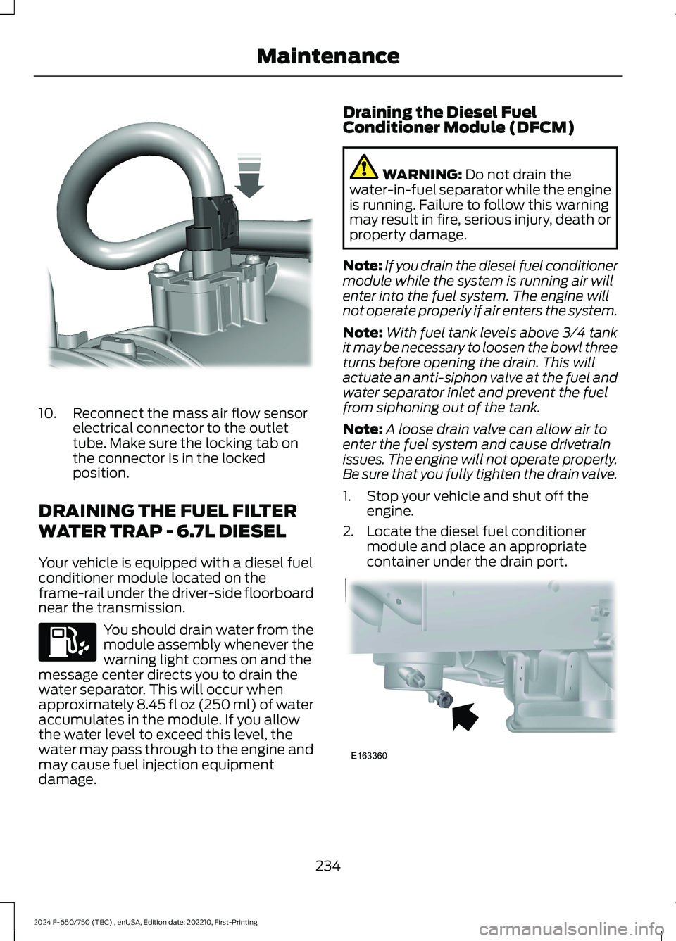
10.Reconnect the mass air flow sensorelectrical connector to the outlettube. Make sure the locking tab onthe connector is in the lockedposition.
DRAINING THE FUEL FILTER
WATER TRAP - 6.7L DIESEL
Your vehicle is equipped with a diesel fuelconditioner module located on theframe-rail under the driver-side floorboardnear the transmission.
You should drain water from themodule assembly whenever thewarning light comes on and themessage center directs you to drain thewater separator. This will occur whenapproximately 8.45 fl oz (250 ml) of wateraccumulates in the module. If you allowthe water level to exceed this level, thewater may pass through to the engine andmay cause fuel injection equipmentdamage.
Draining the Diesel FuelConditioner Module (DFCM)
WARNING: Do not drain thewater-in-fuel separator while the engineis running. Failure to follow this warningmay result in fire, serious injury, death orproperty damage.
Note:If you drain the diesel fuel conditionermodule while the system is running air willenter into the fuel system. The engine willnot operate properly if air enters the system.
Note:With fuel tank levels above 3⁄4 tankit may be necessary to loosen the bowl threeturns before opening the drain. This willactuate an anti-siphon valve at the fuel andwater separator inlet and prevent the fuelfrom siphoning out of the tank.
Note:A loose drain valve can allow air toenter the fuel system and cause drivetrainissues. The engine will not operate properly.Be sure that you fully tighten the drain valve.
1.Stop your vehicle and shut off theengine.
2.Locate the diesel fuel conditionermodule and place an appropriatecontainer under the drain port.
234
2024 F-650/750 (TBC) , enUSA, Edition date: 202210, First-PrintingMaintenanceE317619 E163360