2024 FORD F650/750 brake
[x] Cancel search: brakePage 147 of 386

5.Tighten the nut until the spring is fullycaged and brakes released. Do notloosen or remove the release stud andnut unless you completely assembleand securely clamp the brake chamber.
6.After restoring the air pressure,unscrew and remove the release studand install in the carrying pocket. Installthe access plug.
HILL START ASSIST -
VEHICLES WITH: HYDRAULIC
BRAKES
WARNING: The system does notreplace the parking brake. When youleave your vehicle, always apply theparking brake.
WARNING: You must remain inyour vehicle when the system turns on.At all times you are responsible forcontrolling your vehicle, supervising thesystem, and intervening if required.Failure to follow this instruction couldresult in the loss of control of yourvehicle, personal injury or death.
WARNING: The system will turnoff if a malfunction is apparent or if yourev the engine excessively. Failure to takecare may result in the loss of control ofyour vehicle, serious personal injury ordeath.
The system makes it easier to pull awaywhen your vehicle is on a slope withoutneeding to use the parking brake.
When the system is active, your vehicleremains stationary on the slope for two tothree seconds after you release the brakepedal. This allows time to move your footfrom the brake to the accelerator pedal.The brakes release when the engine has
developed sufficient torque to prevent yourvehicle from rolling down the slope. Thisis an advantage when pulling away on aslope, for example from a car park ramp,traffic lights or when reversing uphill intoa parking space.
When the vehicle is on a slope, the systemwill turn on automatically to preventvehicle rollback.
Note:There is no warning light to indicatethe system is either on or off.
Using Hill Start Assist
1.Press the brake pedal to bring yourvehicle to a complete standstill. Keepthe brake pedal pressed and shift intogear when facing uphill or reverse (R)when facing downhill.
2.If the sensors detect that your vehicleis on a slope, the system automaticallyactivates.
3.When you remove your foot from thebrake pedal, your vehicle remains onthe slope without rolling away forabout two to three seconds. This holdtime automatically extends if you arein the process of driving off.
4.Drive off in the normal manner. Thesystem releases the brakesautomatically.
Note:When you remove your foot from thebrake pedal and press the pedal again whenthe system is active, you will experiencesignificantly reduced brake pedal travel. Thisis normal.
Switching the System On and Off
Vehicles with Manual Transmission
You can switch this feature on or off in theinformation display. The systemremembers the last setting when you startyour vehicle.
143
2024 F-650/750 (TBC) , enUSA, Edition date: 202210, First-PrintingBrakes
Page 148 of 386
Vehicles with Automatic Transmission
When you switch the ignition on, thesystem automatically turns on. You cannotturn the system on or off.
AIR BRAKES
WARNING: Failure to maintainproper air brake adjustment can resultin reduction or loss of braking ability.
WARNING: Do not drive or continueto drive if the low air pressure buzzer issounding or the brake warning light is lit.These warnings indicate that air pressureis not to normal operating level.Continued use of the vehicle could resultin loss of braking ability.
WARNING: Avoid repeated lightapplication of the brake pedal. Thisdepletes air pressure faster and couldresult in loss of braking capability.
WARNING: Do not move thevehicle when the air pressure isinsufficient because the brake systemmay be inoperative.
After starting the engine, allow time for theair compressor to build air pressure to60 psi (414 kPa) before moving yourvehicle.
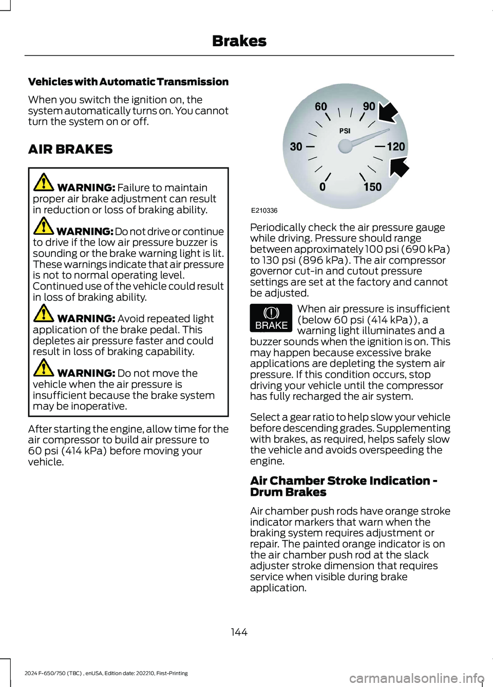
Periodically check the air pressure gaugewhile driving. Pressure should rangebetween approximately 100 psi (690 kPa)to 130 psi (896 kPa). The air compressorgovernor cut-in and cutout pressuresettings are set at the factory and cannotbe adjusted.
When air pressure is insufficient(below 60 psi (414 kPa)), awarning light illuminates and abuzzer sounds when the ignition is on. Thismay happen because excessive brakeapplications are depleting the system airpressure. If this condition occurs, stopdriving your vehicle until the compressorhas fully recharged the air system.
Select a gear ratio to help slow your vehiclebefore descending grades. Supplementingwith brakes, as required, helps safely slowthe vehicle and avoids overspeeding theengine.
Air Chamber Stroke Indication -Drum Brakes
Air chamber push rods have orange strokeindicator markers that warn when thebraking system requires adjustment orrepair. The painted orange indicator is onthe air chamber push rod at the slackadjuster stroke dimension that requiresservice when visible during brakeapplication.
144
2024 F-650/750 (TBC) , enUSA, Edition date: 202210, First-PrintingBrakesE210336 E206772
Page 149 of 386

Only qualified service technicians shouldperform air brake inspection andadjustment or repairs.
Cam Brakes - Automatic SlackAdjusters - Drum Brakes
WARNING: Do not manually adjustthe automatic slack adjusters to correctexcessive push rod stroke as it may resultin reduced brake effectiveness and avehicle crash. Excessive push rod strokeindicates that a problem exists with theautomatic adjuster, with the installationof the adjuster, or with foundation brakecomponents that manual adjustmentdoes not remedy. Seek service from aqualified facility for excessive push rodstroke.
Standard air brakes (cam) are equippedwith automatic brake adjusters. Automaticadjustment occurs during brakeapplications. Inspect brakes for properadjustment at the specified intervals. SeeScheduled Maintenance (page 325).
Emergency Air Brake
WARNING: Do not continue tooperate the vehicle with a failure of oneof the brake systems. Take the vehicleto your dealer for service immediately.
Brake Wear Indicator - Disc Brakes
Inspect the brake wear indicator every timebefore starting the vehicle. The wearindicator length through the hole continuesto reduce depending on the brake padwear. Replace the brake pads immediatelyif the lining material thickness is 0.0787 in(2 mm) or less on either of the brake pads.
EXHAUST BRAKE (IF EQUIPPED)
WARNING: Do not use tow/haulwhen the road surface is slippery. Failureto follow this instruction could result inthe loss of control of your vehicle.
WARNING: Do not use dieselengine exhaust braking when the roadsurface is slippery. Failure to follow thisinstruction could result in the loss ofcontrol of your vehicle.
145
2024 F-650/750 (TBC) , enUSA, Edition date: 202210, First-PrintingBrakesE210337 E392040
Page 150 of 386
Note:Installing an exhaust or auxiliarybrake does not necessarily protect theengine from exceeding the maximumgoverned speed. Use the primary brakes tomake sure the engine never exceeds themaximum governed speed under anycircumstance.
Note:Engine speed has a major influenceon limiting performance. When enginespeed stays at the maximum allowablelevel, the exhaust brake operates at peakperformance.
Note:Exhaust brakes operate effectivelywith automatic transmissions. However,performance varies with engine speed andthe gear selected by the transmission.
An exhaust brake is an auxiliary brakingsystem that assists, but does not replace,the primary brake system. It helps controlvehicle speed. It is not a vehicle-stoppingdevice.
Use the button on the instrument panel, incombination with the accelerator pedal,to maximize the use of the exhaust brakein the following conditions:
•Off-highway driving.
•Mountain driving.
•Heavy traffic.
•High-speed highway driving.
To switch the exhaust brake on, press thebutton. A light on the instrument clusterindicates the system is on. Press the buttonagain to switch it off.
While approaching a steep grade, makesure that the exhaust brake switch is on.The exhaust brake begins working as soonas you remove your foot from theaccelerator pedal.
Before descending a hill or steep grade,always select the proper gear. If you takethe transmission out of gear whiledescending, you may not be able to selectanother gear because of maximumgoverned RPM.
Make sure the engine speed does notexceed the maximum allowable engineRPM. Exceeding the maximum allowableengine RPM can result in damage to theengine. Apply the service brakes to reducethe engine RPM or make a slower descentby using a lower gear.
146
2024 F-650/750 (TBC) , enUSA, Edition date: 202210, First-PrintingBrakesE215226
Page 151 of 386
While driving down a grade, use a lowenough gear to descend safely with aminimum application of the service brakes.As a general guideline, use the same gearas you use to ascend the hill.
Exhaust Brake OperatingCharacteristics
The exhaust brake switches on when youremove your feet from the acceleratorpedal and the exhaust brake is on.
If the brake is working properly, you maynotice:
•A slight change in engine sound whenthe exhaust brake turns on.
•A smooth braking effect. Do not expecta retarding effect similar to sudden,hard application of the service brakes.
•A retarding force possibly felt actingagainst your body during brakeapplication, depending on the gradeand vehicle load. This force helps yourvehicle resist increasing speeds downgrades.
•Engine temperatures remaining in thenormal operating range.
•A drop in engine RPM, depending ongrade and vehicle load, during adescent.
•A decrease in road speed whenapplying the exhaust brake during adescent, except when your vehicle iscarrying a heavy load or the grade isextremely steep. In these instances,you may need to apply the servicebrakes occasionally.
TRAILER BRAKES (IF EQUIPPED)
Trailer Brake Hand Control (If Equipped)
WARNING: The hand controlshould never be used to apply the brakeswhen the tractor and trailer are parkedunattended. Air may leak from thesystem and the vehicle could possiblymove, resulting in possible propertydamage, personal injury or death.
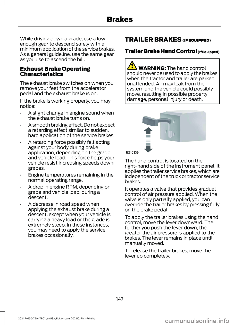
The hand control is located on theright-hand side of the instrument panel. Itapplies the trailer service brakes, which areindependent of the truck or tractor servicebrakes.
It operates a valve that provides gradualcontrol of air pressure applied. When thevalve is only partially applied, you canoverride the trailer brakes by pressing fullyon the brake pedal.
To apply the trailer brakes using the handcontrol, move the lever downward. Thefurther you push the lever down, thegreater the air pressure is applied to thebrakes. The lever remains in place untilmanually moved.
To release the trailer brakes, move thelever up completely.
147
2024 F-650/750 (TBC) , enUSA, Edition date: 202210, First-PrintingBrakesE210339
Page 152 of 386
Trailer Air Supply and ParkingBrake Modular Controls (If Equipped)
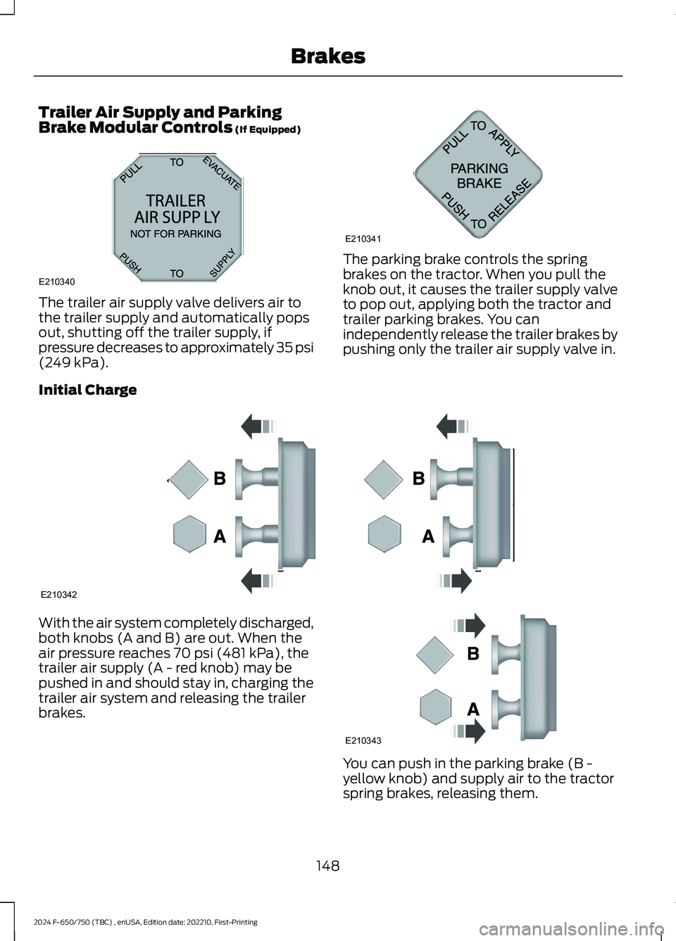
The trailer air supply valve delivers air tothe trailer supply and automatically popsout, shutting off the trailer supply, ifpressure decreases to approximately 35 psi(249 kPa).
The parking brake controls the springbrakes on the tractor. When you pull theknob out, it causes the trailer supply valveto pop out, applying both the tractor andtrailer parking brakes. You canindependently release the trailer brakes bypushing only the trailer air supply valve in.
Initial Charge
With the air system completely discharged,both knobs (A and B) are out. When theair pressure reaches 70 psi (481 kPa), thetrailer air supply (A - red knob) may bepushed in and should stay in, charging thetrailer air system and releasing the trailerbrakes.
You can push in the parking brake (B -yellow knob) and supply air to the tractorspring brakes, releasing them.
148
2024 F-650/750 (TBC) , enUSA, Edition date: 202210, First-PrintingBrakesE210340AB12A320A E210341 E210342 E210343
Page 153 of 386
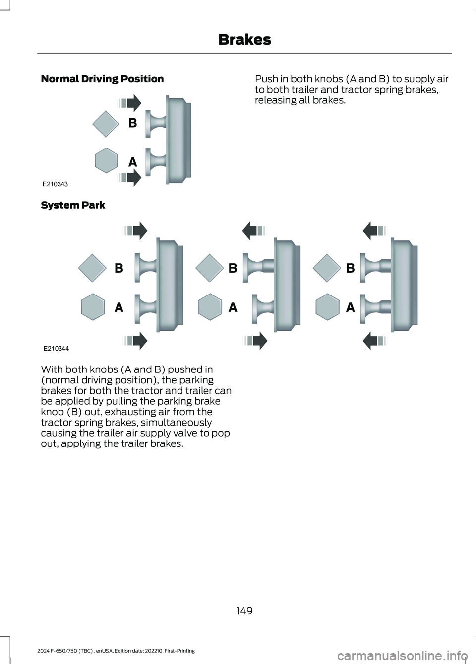
Normal Driving PositionPush in both knobs (A and B) to supply airto both trailer and tractor spring brakes,releasing all brakes.
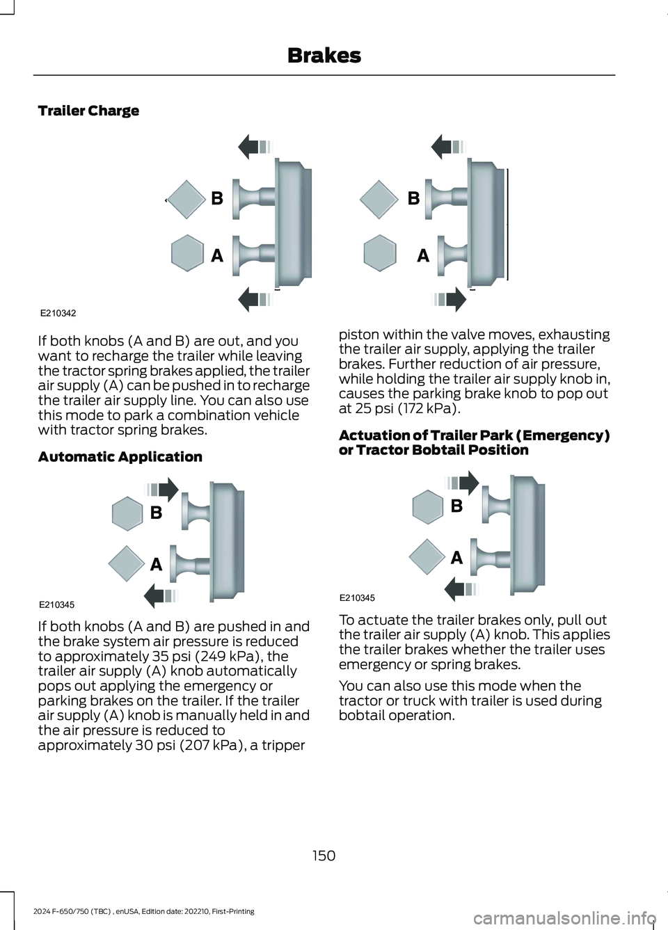
System Park
With both knobs (A and B) pushed in(normal driving position), the parkingbrakes for both the tractor and trailer canbe applied by pulling the parking brakeknob (B) out, exhausting air from thetractor spring brakes, simultaneouslycausing the trailer air supply valve to popout, applying the trailer brakes.
149
2024 F-650/750 (TBC) , enUSA, Edition date: 202210, First-PrintingBrakesE210343 E210344
Page 154 of 386
Trailer Charge
If both knobs (A and B) are out, and youwant to recharge the trailer while leavingthe tractor spring brakes applied, the trailerair supply (A) can be pushed in to rechargethe trailer air supply line. You can also usethis mode to park a combination vehiclewith tractor spring brakes.
Automatic Application
If both knobs (A and B) are pushed in andthe brake system air pressure is reducedto approximately 35 psi (249 kPa), thetrailer air supply (A) knob automaticallypops out applying the emergency orparking brakes on the trailer. If the trailerair supply (A) knob is manually held in andthe air pressure is reduced toapproximately 30 psi (207 kPa), a tripper
piston within the valve moves, exhaustingthe trailer air supply, applying the trailerbrakes. Further reduction of air pressure,while holding the trailer air supply knob in,causes the parking brake knob to pop outat 25 psi (172 kPa).
Actuation of Trailer Park (Emergency)or Tractor Bobtail Position
To actuate the trailer brakes only, pull outthe trailer air supply (A) knob. This appliesthe trailer brakes whether the trailer usesemergency or spring brakes.
You can also use this mode when thetractor or truck with trailer is used duringbobtail operation.
150
2024 F-650/750 (TBC) , enUSA, Edition date: 202210, First-PrintingBrakesE210342 E210345 E210345