2024 FORD F650/750 fuel filter
[x] Cancel search: fuel filterPage 229 of 386

UNDER HOOD OVERVIEW - 6.7L DIESEL
Engine compartment fuse box. See Fuses (page 202).A
Windshield washer fluid reservoir. See Washer Fluid Check (page 249).B
Secondary Cooling System Reservoir. See Engine Coolant Check (page 235).C
Engine coolant reservoir. See Engine Coolant Check (page 235).D
Secondary fuel filter. See Draining the Fuel Filter Water Trap (page 234).E
Engine oil separator. See Changing the Engine Oil and Oil Filter (page 228).F
Engine oil filler cap. See Engine Oil Check (page 227).G
Brake fluid reservoir. See Brake Fluid Check (page 245).H
Power steering fluid reservoir. See Power Steering Fluid Check (page 246).I
Air brake compressor. See Brake System Inspection (page 256).J
Engine oil dipstick. See Engine Oil Dipstick (page 227).K
Air cleaner assembly. See Changing the Engine Air Filter (page 230).L
225
2024 F-650/750 (TBC) , enUSA, Edition date: 202210, First-PrintingMaintenanceE389955
Page 234 of 386
Action and DescriptionMessage
Oil Life: 100%
When the oil change indic-ator resets, the instrumentcluster displays 100%.
Repeat the process if the oilchange indicator does notreset.
CHANGING THE ENGINE AIR
FILTER - 6.7L DIESEL
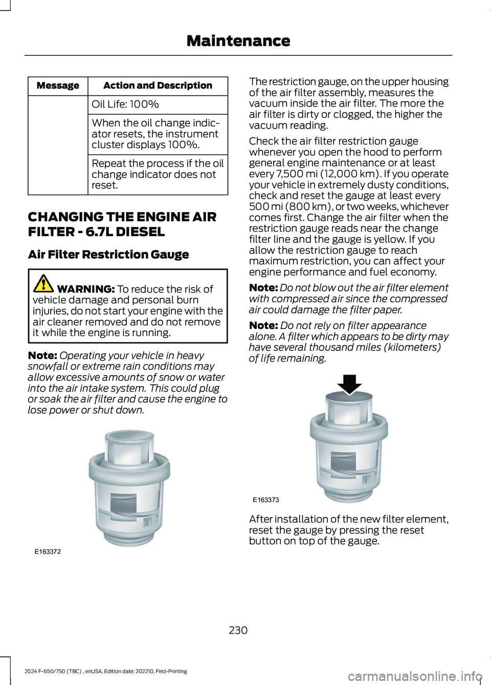
Air Filter Restriction Gauge
WARNING: To reduce the risk ofvehicle damage and personal burninjuries, do not start your engine with theair cleaner removed and do not removeit while the engine is running.
Note:Operating your vehicle in heavysnowfall or extreme rain conditions mayallow excessive amounts of snow or waterinto the air intake system. This could plugor soak the air filter and cause the engine tolose power or shut down.
The restriction gauge, on the upper housingof the air filter assembly, measures thevacuum inside the air filter. The more theair filter is dirty or clogged, the higher thevacuum reading.
Check the air filter restriction gaugewhenever you open the hood to performgeneral engine maintenance or at leastevery 7,500 mi (12,000 km). If you operateyour vehicle in extremely dusty conditions,check and reset the gauge at least every500 mi (800 km), or two weeks, whichevercomes first. Change the air filter when therestriction gauge reads near the changefilter line and the gauge is yellow. If youallow the restriction gauge to reachmaximum restriction, you can affect yourengine performance and fuel economy.
Note:Do not blow out the air filter elementwith compressed air since the compressedair could damage the filter paper.
Note:Do not rely on filter appearancealone. A filter which appears to be dirty mayhave several thousand miles (kilometers)of life remaining.
After installation of the new filter element,reset the gauge by pressing the resetbutton on top of the gauge.
230
2024 F-650/750 (TBC) , enUSA, Edition date: 202210, First-PrintingMaintenanceE163372 E163373
Page 238 of 386
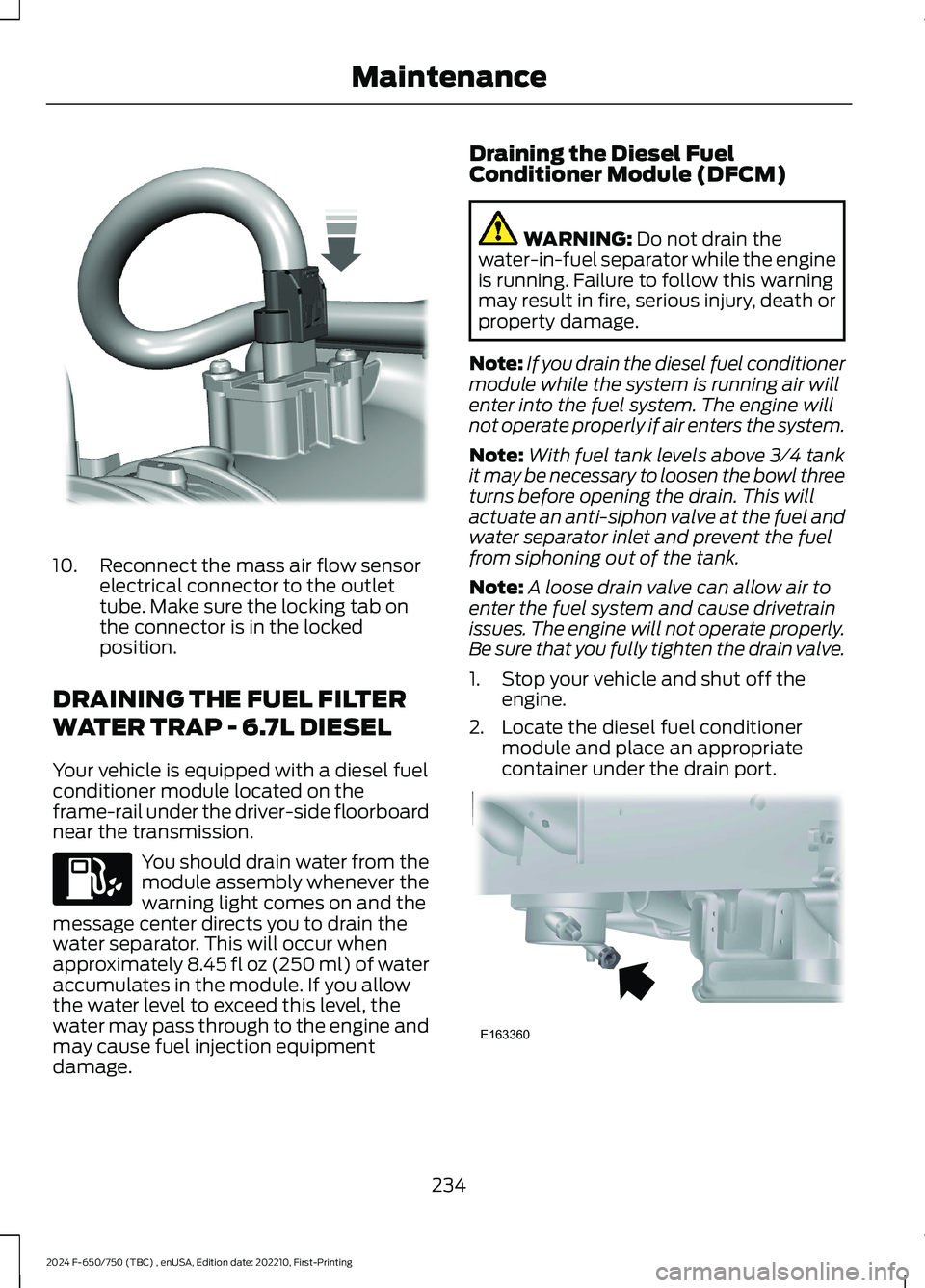
10.Reconnect the mass air flow sensorelectrical connector to the outlettube. Make sure the locking tab onthe connector is in the lockedposition.
DRAINING THE FUEL FILTER
WATER TRAP - 6.7L DIESEL
Your vehicle is equipped with a diesel fuelconditioner module located on theframe-rail under the driver-side floorboardnear the transmission.
You should drain water from themodule assembly whenever thewarning light comes on and themessage center directs you to drain thewater separator. This will occur whenapproximately 8.45 fl oz (250 ml) of wateraccumulates in the module. If you allowthe water level to exceed this level, thewater may pass through to the engine andmay cause fuel injection equipmentdamage.
Draining the Diesel FuelConditioner Module (DFCM)
WARNING: Do not drain thewater-in-fuel separator while the engineis running. Failure to follow this warningmay result in fire, serious injury, death orproperty damage.
Note:If you drain the diesel fuel conditionermodule while the system is running air willenter into the fuel system. The engine willnot operate properly if air enters the system.
Note:With fuel tank levels above 3⁄4 tankit may be necessary to loosen the bowl threeturns before opening the drain. This willactuate an anti-siphon valve at the fuel andwater separator inlet and prevent the fuelfrom siphoning out of the tank.
Note:A loose drain valve can allow air toenter the fuel system and cause drivetrainissues. The engine will not operate properly.Be sure that you fully tighten the drain valve.
1.Stop your vehicle and shut off theengine.
2.Locate the diesel fuel conditionermodule and place an appropriatecontainer under the drain port.
234
2024 F-650/750 (TBC) , enUSA, Edition date: 202210, First-PrintingMaintenanceE317619 E163360
Page 239 of 386
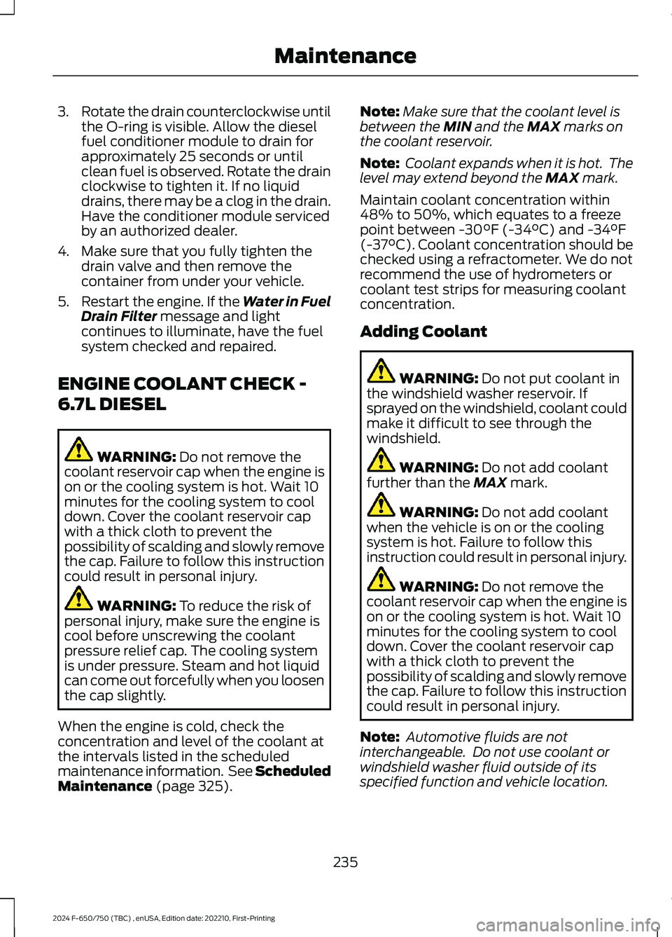
3.Rotate the drain counterclockwise untilthe O-ring is visible. Allow the dieselfuel conditioner module to drain forapproximately 25 seconds or untilclean fuel is observed. Rotate the drainclockwise to tighten it. If no liquiddrains, there may be a clog in the drain.Have the conditioner module servicedby an authorized dealer.
4.Make sure that you fully tighten thedrain valve and then remove thecontainer from under your vehicle.
5.Restart the engine. If the Water in FuelDrain Filter message and lightcontinues to illuminate, have the fuelsystem checked and repaired.
ENGINE COOLANT CHECK -
6.7L DIESEL
WARNING: Do not remove thecoolant reservoir cap when the engine ison or the cooling system is hot. Wait 10minutes for the cooling system to cooldown. Cover the coolant reservoir capwith a thick cloth to prevent thepossibility of scalding and slowly removethe cap. Failure to follow this instructioncould result in personal injury.
WARNING: To reduce the risk ofpersonal injury, make sure the engine iscool before unscrewing the coolantpressure relief cap. The cooling systemis under pressure. Steam and hot liquidcan come out forcefully when you loosenthe cap slightly.
When the engine is cold, check theconcentration and level of the coolant atthe intervals listed in the scheduledmaintenance information. See ScheduledMaintenance (page 325).
Note:Make sure that the coolant level isbetween the MIN and the MAX marks onthe coolant reservoir.
Note: Coolant expands when it is hot. Thelevel may extend beyond the MAX mark.
Maintain coolant concentration within48% to 50%, which equates to a freezepoint between -30°F (-34°C) and -34°F(-37°C). Coolant concentration should bechecked using a refractometer. We do notrecommend the use of hydrometers orcoolant test strips for measuring coolantconcentration.
Adding Coolant
WARNING: Do not put coolant inthe windshield washer reservoir. Ifsprayed on the windshield, coolant couldmake it difficult to see through thewindshield.
WARNING: Do not add coolantfurther than the MAX mark.
WARNING: Do not add coolantwhen the vehicle is on or the coolingsystem is hot. Failure to follow thisinstruction could result in personal injury.
WARNING: Do not remove thecoolant reservoir cap when the engine ison or the cooling system is hot. Wait 10minutes for the cooling system to cooldown. Cover the coolant reservoir capwith a thick cloth to prevent thepossibility of scalding and slowly removethe cap. Failure to follow this instructioncould result in personal injury.
Note: Automotive fluids are notinterchangeable. Do not use coolant orwindshield washer fluid outside of itsspecified function and vehicle location.
235
2024 F-650/750 (TBC) , enUSA, Edition date: 202210, First-PrintingMaintenance
Page 253 of 386

4.On the wall or screen you will observea flat zone of high intensity lightlocated at the top of the right handportion of the beam pattern. If the topedge of the high intensity light zone isnot at the horizontal reference line, theheadlamp will need to be adjusted.
5.Locate the vertical adjuster on eachheadlamp. Using a Phillips #2screwdriver, turn the adjuster eitherclockwise or counterclockwise in orderto adjust the vertical aim of theheadlamp.
6.Repeat Steps 3 thru 5 to adjust theother headlamp.
7.Close the hood and turn off the lamps.
Horizontal Aim Adjustment
Horizontal aim is not required for thisvehicle and is not adjustable.
WASHER FLUID CHECK
WARNING: If you operate yourvehicle in temperatures below 40°F(5°C), use washer fluid with antifreezeprotection. Failure to use washer fluidwith antifreeze protection in coldweather could result in impairedwindshield vision and increase the riskof injury or accident.
Add fluid to fill the reservoir if the level islow. Only use a washer fluid that meetsFord specifications. See Capacities andSpecifications (page 291).
State or local regulations on volatileorganic compounds may restrict the useof methanol, a common windshield washerantifreeze additive. Washer fluidscontaining non-methanol antifreezeagents should be used only if they providecold weather protection without damagingthe vehicle’s paint finish, wiper blades orwasher system.
FUEL FILTER - 7.3L
Your vehicle is equipped with a lifetimefuel filter that is integrated with the fueltank. Regular maintenance or replacementis not needed.
CHECKING THE WIPER
BLADES
249
2024 F-650/750 (TBC) , enUSA, Edition date: 202210, First-PrintingMaintenanceE142465 E163806 E142463
Page 255 of 386

Headlamp bulbs must be marked with anauthorized D.O.T. marking for NorthAmerica to make sure they have the properlamp performance, light brightness, lightpattern and safe visibility.
Install in the reverse order unless otherwisestated.
Headlamp Bulbs
1.Switch all of the lamps and the ignitionoff.
2.Remove the headlamp. SeeRemoving a Headlamp (page 250).
3.Release the clip and remove the bulb.
Note:Do not touch the bulb glass.
Note:If the bulb is accidentally touched, itshould be cleaned with rubbing alcoholbefore being used.
Front Clearance and IdentificationLamp (If Equipped)
1.Switch all of the lamps and the ignitionoff.
2.Remove the screw and lens from thelamp assembly.
3.Press the bulb in and turn the bulbcounterclockwise to remove it.
Brake Lamp, Rear Lamp, RearDirection Indicator, License PlateLamp and Reverse Lamp
1.Switch all of the lamps and the ignitionoff.
2.Remove the four screws and the lamplens from lamp assembly.
3.Remove the bulb by pulling it straightout.
CHANGING THE ENGINE-
MOUNTED AND DIESEL FUEL
CONDITIONER MODULE FUEL
FILTERS - 6.7L DIESEL
WARNING: Do not dispose of fuelin the household refuse or the publicsewage system. Use an authorized wastedisposal facility.
Your vehicle has two fuel filters. The firstfilter mounts on top of the engine on theleft-hand side. The second filter is insidethe diesel fuel conditioner module. Themodule is mounted between the inboardside of the fuel tank and the frame rail.
251
2024 F-650/750 (TBC) , enUSA, Edition date: 202210, First-PrintingMaintenanceE163825 E163828
Page 256 of 386
Regular fuel filter changes are animportant part of engine maintenance;failing to keep with the scheduledmaintenance could lead to engineperformance issues and fuel injectionsystem damage. See ScheduledMaintenance (page 325).
Use only recommended service partsconforming to specifications. SeeMotorcraft Parts (page 293).
Note:Using fuel that has high levels ofimpurities may require more frequent filterreplacements than the service intervalspecifies.
Diesel Fuel Conditioner ModuleFilter
Removal
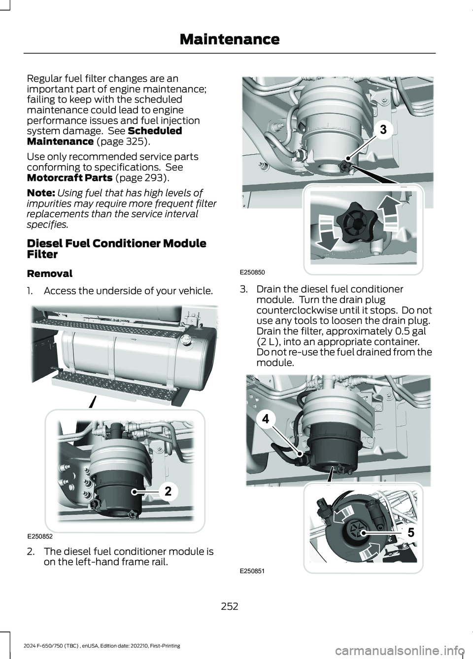
1.Access the underside of your vehicle.
2.The diesel fuel conditioner module ison the left-hand frame rail.
3.Drain the diesel fuel conditionermodule. Turn the drain plugcounterclockwise until it stops. Do notuse any tools to loosen the drain plug.Drain the filter, approximately 0.5 gal(2 L), into an appropriate container.Do not re-use the fuel drained from themodule.
252
2024 F-650/750 (TBC) , enUSA, Edition date: 202210, First-PrintingMaintenanceE250852 E250850 E250851
Page 257 of 386
4.Disconnect the electrical connector.
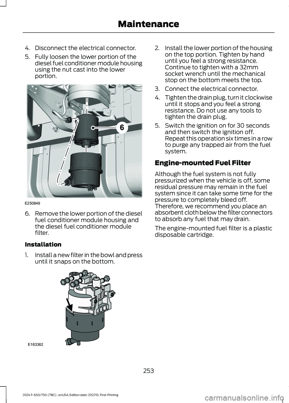
5.Fully loosen the lower portion of thediesel fuel conditioner module housingusing the nut cast into the lowerportion.
6.Remove the lower portion of the dieselfuel conditioner module housing andthe diesel fuel conditioner modulefilter.
Installation
1.Install a new filter in the bowl and pressuntil it snaps on the bottom.
2.Install the lower portion of the housingon the top portion. Tighten by handuntil you feel a strong resistance.Continue to tighten with a 32mmsocket wrench until the mechanicalstop on the bottom meets the top.
3.Connect the electrical connector.
4.Tighten the drain plug, turn it clockwiseuntil it stops and you feel a strongresistance. Do not use any tools totighten the drain plug.
5.Switch the ignition on for 30 secondsand then switch the ignition off.Repeat this operation six times in a rowto purge any trapped air from the fuelsystem.
Engine-mounted Fuel Filter
Although the fuel system is not fullypressurized when the vehicle is off, someresidual pressure may remain in the fuelsystem since it can take some time for thepressure to completely bleed off.Therefore, we recommend you place anabsorbent cloth below the filter connectorsto absorb any fuel that may drain.
The engine-mounted fuel filter is a plasticdisposable cartridge.
253
2024 F-650/750 (TBC) , enUSA, Edition date: 202210, First-PrintingMaintenanceE250849 E163362