2024 FORD F650/750 automatic transmission
[x] Cancel search: automatic transmissionPage 187 of 386
ESSENTIAL TOWING CHECKS
See Load limits in the Load Carryingchapter for load specification terms foundon the tire label and Safety Compliancelabel and instructions on calculating yourvehicle's load.
Remember to account for the trailertongue weight as part of your vehicle loadwhen calculating the total vehicle weight.
Hitches
Do not use a hitch that either clamps ontothe bumper or attaches to the axle. Youmust distribute the load in your trailer sothat 10-15% of the total weight of thetrailer is on the tongue.
Safety Chains
Note:Do not attach safety chains to thebumper.
Always connect the safety chains to theframe or hook retainers of your vehiclehitch.
To connect the safety chains, cross thechains under the trailer tongue and allowenough slack for turning tight corners. Donot allow the chains to drag on the ground.
Trailer Brakes
WARNING: Do not connect atrailer's hydraulic brake system directlyto your vehicle's brake system. Yourvehicle may not have enough brakingpower and your chances of having acollision greatly increase.
Electric brakes and manual, automatic orsurge-type trailer brakes are safe if youinstall them properly and adjust them tothe manufacturer's specifications. Thetrailer brakes must meet local and federalregulations.
The rating for the tow vehicle's brakingsystem operation is at the gross vehicleweight rating, not the gross combinedweight rating.
Trailer Lamps
WARNING: Never connect anytrailer lamp wiring to the vehicle's taillamp wiring; this may damage theelectrical system resulting in fire. Contactyour authorized dealer as soon aspossible for assistance in proper trailertow wiring installation. Additionalelectrical equipment may be required.
Trailer lamps are required on most towedvehicles. Make sure all running lights, brakelights, turn signals and hazard lights areworking.
Before Towing a Trailer
Practice turning, stopping and backing upto get the feel of your vehicle-trailercombination before starting on a trip.When turning, make wider turns so thetrailer wheels clear curbs and otherobstacles.
When Towing a Trailer
•Check your hitch, electrical connectionsand trailer wheel lug nuts thoroughlyafter you have traveled 50 mph(80 km/h).
•When stopped in congested or heavytraffic during hot weather, place thetransmission in park (P) or neutral (N)to aid engine and transmission coolingand to help air conditioningperformance.
•Turn off the speed control with heavyloads or in hilly terrain. The speedcontrol may turn off automaticallywhen you are towing on long, steepgrades.
183
2024 F-650/750 (TBC) , enUSA, Edition date: 202210, First-PrintingTowing
Page 194 of 386
HAZARD FLASHERS
Note:If used when the vehicle is notrunning, the battery loses charge. As a result,there may be insufficient power to restartyour vehicle.
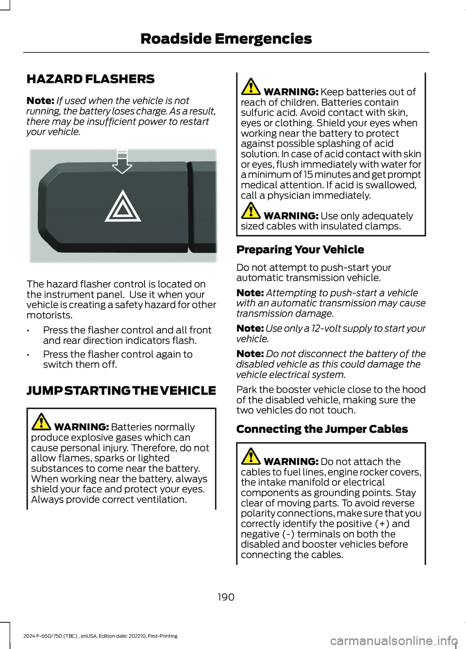
The hazard flasher control is located onthe instrument panel. Use it when yourvehicle is creating a safety hazard for othermotorists.
•Press the flasher control and all frontand rear direction indicators flash.
•Press the flasher control again toswitch them off.
JUMP STARTING THE VEHICLE
WARNING: Batteries normallyproduce explosive gases which cancause personal injury. Therefore, do notallow flames, sparks or lightedsubstances to come near the battery.When working near the battery, alwaysshield your face and protect your eyes.Always provide correct ventilation.
WARNING: Keep batteries out ofreach of children. Batteries containsulfuric acid. Avoid contact with skin,eyes or clothing. Shield your eyes whenworking near the battery to protectagainst possible splashing of acidsolution. In case of acid contact with skinor eyes, flush immediately with water fora minimum of 15 minutes and get promptmedical attention. If acid is swallowed,call a physician immediately.
WARNING: Use only adequatelysized cables with insulated clamps.
Preparing Your Vehicle
Do not attempt to push-start yourautomatic transmission vehicle.
Note:Attempting to push-start a vehiclewith an automatic transmission may causetransmission damage.
Note:Use only a 12-volt supply to start yourvehicle.
Note:Do not disconnect the battery of thedisabled vehicle as this could damage thevehicle electrical system.
Park the booster vehicle close to the hoodof the disabled vehicle, making sure thetwo vehicles do not touch.
Connecting the Jumper Cables
WARNING: Do not attach thecables to fuel lines, engine rocker covers,the intake manifold or electricalcomponents as grounding points. Stayclear of moving parts. To avoid reversepolarity connections, make sure that youcorrectly identify the positive (+) andnegative (-) terminals on both thedisabled and booster vehicles beforeconnecting the cables.
190
2024 F-650/750 (TBC) , enUSA, Edition date: 202210, First-PrintingRoadside EmergenciesE304635
Page 219 of 386
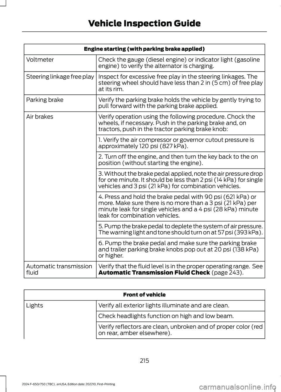
Engine starting (with parking brake applied)
Check the gauge (diesel engine) or indicator light (gasolineengine) to verify the alternator is charging.Voltmeter
Inspect for excessive free play in the steering linkages. Thesteering wheel should have less than 2 in (5 cm) of free playat its rim.
Steering linkage free play
Verify the parking brake holds the vehicle by gently trying topull forward with the parking brake applied.Parking brake
Verify operation using the following procedure. Chock thewheels, if necessary. Push in the parking brake and, ontractors, push in the tractor parking brake knob:
Air brakes
1. Verify the air compressor or governor cutout pressure isapproximately 120 psi (827 kPa).
2. Turn off the engine, and then turn the key back to the onposition (without starting the engine).
3. Without the brake pedal applied, note the air pressure dropfor one minute. It should be less than 2 psi (14 kPa) for singlevehicles and 3 psi (21 kPa) for combination vehicles.
4. Press and hold the brake pedal with 90 psi (621 kPa) ormore. Make sure there is no more than a 3 psi (21 kPa) perminute leak for single vehicles and a 4 psi (28 kPa) minuteleak for combination vehicles.
5. Pump the brake pedal to deplete the system of air pressure.The warning light and tone should turn on at 57 psi (393 kPa).
6. Pump the brake pedal and make sure the parking brakeand trailer parking brake knobs pop out at 20 psi (138 kPa)or higher.
Verify that the fluid level is in the proper operating range. SeeAutomatic Transmission Fluid Check (page 243).Automatic transmissionfluid
Front of vehicle
Verify all exterior lights illuminate and are clean.Lights
Check headlights function on high and low beam.
Verify reflectors are clean, unbroken and of proper color (redon rear, amber elsewhere).
215
2024 F-650/750 (TBC) , enUSA, Edition date: 202210, First-PrintingVehicle Inspection Guide
Page 230 of 386

UNDER HOOD OVERVIEW - 7.3L
Engine compartment fuse box. See Fuses (page 202).A
Engine oil dipstick. See Engine Oil Dipstick (page 227).B
Windshield washer fluid reservoir. See Washer Fluid Check (page 249).C
Automatic transmission fluid dipstick. See Automatic Transmission FluidCheck (page 243).D
Engine coolant reservoir. See Engine Coolant Check (page 238).E
Engine oil filler cap. See Engine Oil Check (page 227).F
Brake fluid reservoir. See Brake Fluid Check (page 245).G
Power steering fluid reservoir. See Power Steering Fluid Check (page 246).H
Air cleaner assembly. See Changing the Engine Air Filter (page 232).I
226
2024 F-650/750 (TBC) , enUSA, Edition date: 202210, First-PrintingMaintenanceE330964
Page 247 of 386
At this time, you may notice the coolanttemperature gauge moves toward the redzone and a message may appear in theinformation display.
You may notice a reduction in vehiclespeed caused by reduced engine power inorder to manage the engine coolanttemperature. Your vehicle may enter thismode if certain high-temperature andhigh-load conditions take place. Theamount of speed reduction depends onvehicle loading, grade and ambienttemperature. If this occurs, there is noneed to pull off the road. You can continueto drive your vehicle.
The air conditioning may turn on and offduring severe operating conditions toprotect the engine from overheating. Whenthe coolant temperature decreases to thenormal operating temperature, the airconditioning turns on.
If the coolant temperature gauge movesfully into the red zone, or if the coolanttemperature warning or service enginesoon messages appear in your informationdisplay, do the following:
1.Pull off the road as soon as safelypossible and shift the transmission intopark (P).
2.Leave the engine running until thecoolant temperature gauge needlereturns to the normal position. Afterseveral minutes, if the temperaturedoes not drop, follow the remainingsteps.
3.Switch the engine off and wait for it tocool. Check the coolant level.
4.If the coolant level is at or below theminimum mark, add prediluted coolantimmediately.
5.If the coolant level is normal, restartthe engine and continue.
AUTOMATIC TRANSMISSION
FLUID CHECK
The transmission does not consume fluid.However, check the fluid level if thetransmission is not working properly, forexample if the transmission slips, shiftsslowly or if there are signs of fluid loss.
Replace the transmission fluid and filteron your vehicle at the specified serviceinterval. See Scheduled Maintenance(page 325).
Automatic transmission fluid expandswhen warmed. To check the fluid levelconsistently and accurately, do thefollowing:
1.Drive the vehicle until it reaches normaloperating temperature. This may takeup to 20 mi (30 km). Make sure thatthe transmission fluid temperaturegauge on the instrument cluster iswithin normal operating temperature196–215°F (91–102°C) beforechecking.
2.Make sure that your vehicle is on levelground.
3.With the engine running, parking brakeengaged and your foot on the brakepedal, move the gearshift lever throughall of the gear ranges. Allow sufficienttime for each gear to engage.
4.Make sure the parking brake is on. Makesure the transmission is in park (P) orneutral (N) and leave the enginerunning.
5.Open the hood. See Opening andClosing the Hood (page 223).
6.Remove the dipstick and wipe it witha clean, lint-free cloth. See UnderHood Overview (page 225).
7.Replace the dipstick and remove itagain to check the fluid level.
243
2024 F-650/750 (TBC) , enUSA, Edition date: 202210, First-PrintingMaintenance
Page 248 of 386
8.If the fluid level is correct, replace thedipstick and make sure it is fully seated.
Note:If the fluid level is between themaximum and minimum marks, the fluidlevel is acceptable. Do not add fluid.
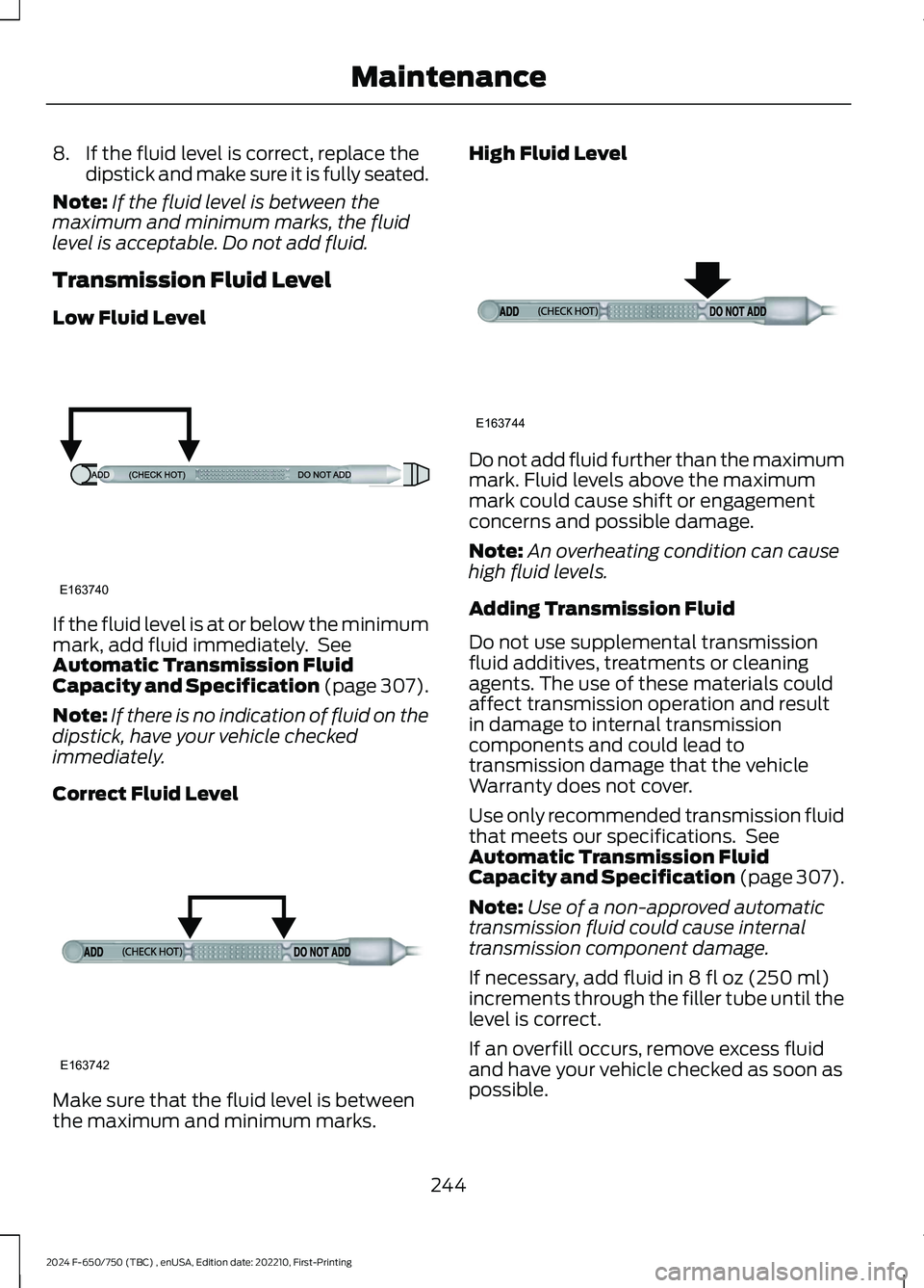
Transmission Fluid Level
Low Fluid Level
If the fluid level is at or below the minimummark, add fluid immediately. SeeAutomatic Transmission FluidCapacity and Specification (page 307).
Note:If there is no indication of fluid on thedipstick, have your vehicle checkedimmediately.
Correct Fluid Level
Make sure that the fluid level is betweenthe maximum and minimum marks.
High Fluid Level
Do not add fluid further than the maximummark. Fluid levels above the maximummark could cause shift or engagementconcerns and possible damage.
Note:An overheating condition can causehigh fluid levels.
Adding Transmission Fluid
Do not use supplemental transmissionfluid additives, treatments or cleaningagents. The use of these materials couldaffect transmission operation and resultin damage to internal transmissioncomponents and could lead totransmission damage that the vehicleWarranty does not cover.
Use only recommended transmission fluidthat meets our specifications. SeeAutomatic Transmission FluidCapacity and Specification (page 307).
Note:Use of a non-approved automatictransmission fluid could cause internaltransmission component damage.
If necessary, add fluid in 8 fl oz (250 ml)increments through the filler tube until thelevel is correct.
If an overfill occurs, remove excess fluidand have your vehicle checked as soon aspossible.
244
2024 F-650/750 (TBC) , enUSA, Edition date: 202210, First-PrintingMaintenanceE163740 E163742 E163744
Page 311 of 386
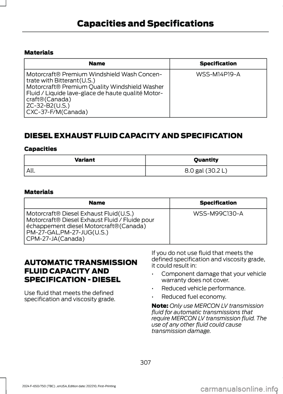
Materials
SpecificationName
WSS-M14P19-AMotorcraft® Premium Windshield Wash Concen-trate with Bitterant(U.S.)Motorcraft® Premium Quality Windshield WasherFluid / Liquide lave-glace de haute qualité Motor-craft®(Canada)ZC-32-B2(U.S.)CXC-37-F/M(Canada)
DIESEL EXHAUST FLUID CAPACITY AND SPECIFICATION
Capacities
QuantityVariant
8.0 gal (30.2 L)All.
Materials
SpecificationName
WSS-M99C130-AMotorcraft® Diesel Exhaust Fluid(U.S.)Motorcraft® Diesel Exhaust Fluid / Fluide pouréchappement diesel Motorcraft®(Canada)PM-27-GAL,PM-27-JUG(U.S.)CPM-27-JA(Canada)
AUTOMATIC TRANSMISSION
FLUID CAPACITY AND
SPECIFICATION - DIESEL
Use fluid that meets the definedspecification and viscosity grade.
If you do not use fluid that meets thedefined specification and viscosity grade,it could result in:
•Component damage that your vehiclewarranty does not cover.
•Reduced vehicle performance.
•Reduced fuel economy.
Note:Only use MERCON LV transmissionfluid for automatic transmissions thatrequire MERCON LV transmission fluid. Theuse of any other fluid could causetransmission damage.
307
2024 F-650/750 (TBC) , enUSA, Edition date: 202210, First-PrintingCapacities and Specifications
Page 312 of 386
Capacities
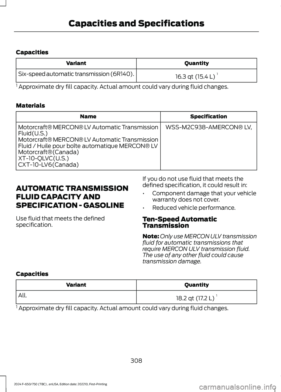
QuantityVariant
16.3 qt (15.4 L)1Six-speed automatic transmission (6R140).
1 Approximate dry fill capacity. Actual amount could vary during fluid changes.
Materials
SpecificationName
WSS-M2C938-AMERCON® LV,Motorcraft® MERCON® LV Automatic TransmissionFluid(U.S.)Motorcraft® MERCON® LV Automatic TransmissionFluid / Huile pour boîte automatique MERCON® LVMotorcraft®(Canada)XT-10-QLVC(U.S.)CXT-10-LV6(Canada)
AUTOMATIC TRANSMISSION
FLUID CAPACITY AND
SPECIFICATION - GASOLINE
Use fluid that meets the definedspecification.
If you do not use fluid that meets thedefined specification, it could result in:
•Component damage that your vehiclewarranty does not cover.
•Reduced vehicle performance.
Ten-Speed AutomaticTransmission
Note:Only use MERCON ULV transmissionfluid for automatic transmissions thatrequire MERCON ULV transmission fluid.The use of any other fluid could causetransmission damage.
Capacities
QuantityVariant
18.2 qt (17.2 L)1All.
1 Approximate dry fill capacity. Actual amount could vary during fluid changes.
308
2024 F-650/750 (TBC) , enUSA, Edition date: 202210, First-PrintingCapacities and Specifications