2024 FORD F650/750 height
[x] Cancel search: heightPage 47 of 386

2.Release the button and pull down onthe height adjuster to make sure it islocked in place.
SEATBELT WARNING LAMP
AND INDICATOR CHIME
This lamp illuminates and anindicator chime will sound if thedriver seatbelt has not beenfastened when the vehicle's ignition isturned on.
Conditions of operation
ThenIf
The seatbelt warning lamp illuminates andthe indicator chime sounds for a fewseconds.
The driver seatbelt is not buckled beforethe ignition switch is turned to the on posi-tion...
The seatbelt warning lamp and indicatorchime turn off.The driver seatbelt is buckled while thewarning lamp is illuminated and the indic-ator chime is sounding...
The seatbelt warning lamp and indicatorchime remain off.The driver seatbelt is buckled before theignition switch is turned to the on position...
SEATBELT REMINDER
Belt-Minder™
This feature supplements the safety beltwarning function by providing additionalreminders that intermittently sound a toneand illuminate the safety belt warning lightwhen you are in the driver seat or you havea front seat passenger and a safety belt isunbuckled.
The system uses information from thefront passenger sensing system todetermine if a front seat passenger ispresent and therefore potentially in needof a warning. To avoid activating theBelt-Minder feature for objects you placein the front passenger seat, only the frontseat passengers receive warnings asdetermined by the front passenger sensingsystem.
If the Belt-Minder warnings expire(warnings for about five minutes) for onepassenger (driver or front passenger), theother passenger can still cause theBelt-Minder feature to turn on.
43
2024 F-650/750 (TBC) , enUSA, Edition date: 202210, First-PrintingSeatbeltsE71880
Page 49 of 386

4.While the safety belt warning light ison, buckle and then unbuckle thesafety belt. After Step 4, the safety beltwarning light flashes for confirmation.
•This will switch the feature off for thatseating position if it is currently on.
•This will switch the feature on for thatseating position if it is currently off.
CHILD RESTRAINT AND
SEATBELT MAINTENANCE
Inspect the vehicle seatbelts and childsafety seat systems periodically to makesure they work properly and are notdamaged. Inspect the vehicle and childrestraint seatbelts to make sure there areno nicks, tears or cuts. Replace ifnecessary. All vehicle seatbelt assemblies,including retractors, buckles, front seatbeltbuckle assemblies, buckle supportassemblies (slide bar-if equipped),shoulder belt height adjusters (ifequipped), shoulder belt guide on seatbackrest (if equipped), child safety seatLATCH and tether anchors, and attachinghardware, should be inspected after acrash. Read the child restraintmanufacturer's instructions for additionalinspection and maintenance informationspecific to the child restraint.
We recommend that all seatbeltassemblies in use in vehicles involved in acrash be replaced. However, if the crashwas minor and an authorized dealer findsthat the belts do not show damage andcontinue to operate properly, they do notneed to be replaced. Seatbelt assembliesnot in use during a crash should also beinspected and replaced if either damageor improper operation is noted.
Properly care for seatbelts. See VehicleCare (page 262).
SEATBELT EXTENSIONS
WARNING: Persons who fit intothe vehicle's seatbelt should not use anextension. Unnecessary use could resultin serious personal injury in the event ofa crash.
WARNING: Only use extensionsprovided free of charge by our dealers.The dealer will provide an extensiondesigned specifically for this vehicle,model year and seating position. The useof an extension intended for anothervehicle, model year or seating positionmay not offer you the full protection ofyour vehicle's seatbelt restraint system.
WARNING: Never use seatbeltextensions to install child restraints.
WARNING: Do not use extensionsto change the way the seatbelt fitsacross the torso, over the lap or to makethe seatbelt buckle easier to reach.
If, because of body size or driving position,it is not possible to properly fasten theseatbelt over your lap and shoulder, anextension that is compatible with theseatbelts is available free of charge fromour dealers. Only use our seatbeltextensions made by the original equipmentseatbelt manufacturer with our seatbelts.Ask your authorized dealer if your extensionis compatible with your vehicle restraintsystem.
45
2024 F-650/750 (TBC) , enUSA, Edition date: 202210, First-PrintingSeatbelts
Page 62 of 386

Note:Using much larger tires or equippingvehicle accessories such as snowplows canmodify your vehicle's ride height anddegrade automatic high beam controlperformance.
A camera sensor, centrally mountedbehind the windshield of your vehicle,continuously monitors conditions to turnthe high beams on and off.
Once the system is active, the high beamsturn on if:
•The ambient light level is low enough.
•There is no traffic in front of yourvehicle.
•The vehicle speed is greater thanapproximately 32 mph (51 km/h).
The system turns the high beams off if:
•The ambient light level is high enoughthat high beams are not required.
•The system detects an approachingvehicle's headlamps or tail lamps.
•The vehicle speed falls belowapproximately 27 mph (44 km/h).
•The system detects severe rain, snowor fog.
•The camera is blocked.
Switching the System On and Off
Switch the system on using the informationdisplay. See Information Displays (page71).
Switch the lighting control to theautolamps position. See Autolamps(page 56).
Overriding the System
Push the lever away from you to switchbetween high beam and low beam.
Automatic High Beam Indicator
The indicator illuminates toconfirm when the system isready to assist.
DIRECTION INDICATORS
Push the lever up or down to usethe direction indicators.
Note:Tap the lever up or down to make thedirection indicators flash three times.
INTERIOR LAMPS
The lamps turn on under the followingconditions:
•You open any door.
•You press a remote control button.
58
2024 F-650/750 (TBC) , enUSA, Edition date: 202210, First-PrintingLightingE142451 E146105 E311431 E67018
Page 97 of 386

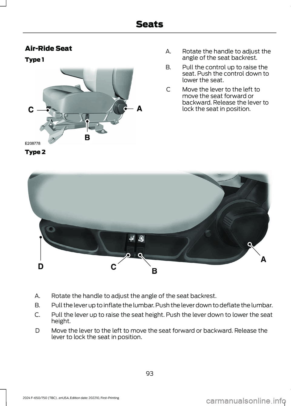
Air-Ride Seat
Type 1
Rotate the handle to adjust theangle of the seat backrest.A.
Pull the control up to raise theseat. Push the control down tolower the seat.
B.
Move the lever to the left tomove the seat forward orbackward. Release the lever tolock the seat in position.
C
Type 2
Rotate the handle to adjust the angle of the seat backrest.A.
Pull the lever up to inflate the lumbar. Push the lever down to deflate the lumbar.B.
Pull the lever up to raise the seat height. Push the lever down to lower the seatheight.C.
Move the lever to the left to move the seat forward or backward. Release thelever to lock the seat in position.D
93
2024 F-650/750 (TBC) , enUSA, Edition date: 202210, First-PrintingSeatsE208778 E298809
Page 183 of 386

AIR SUSPENSION
Note:Do not operate your vehicle withoutair in the suspension springs. Operating yourvehicle without air in the suspension springsdamages the suspension, degrades rideperformance and may cause propertydamage.
The air suspension system automaticallyadjusts to different loads to maintain aconstant frame height, allows for ease ofvehicle loading, provides improved vehicleride, and increased driver comfort.
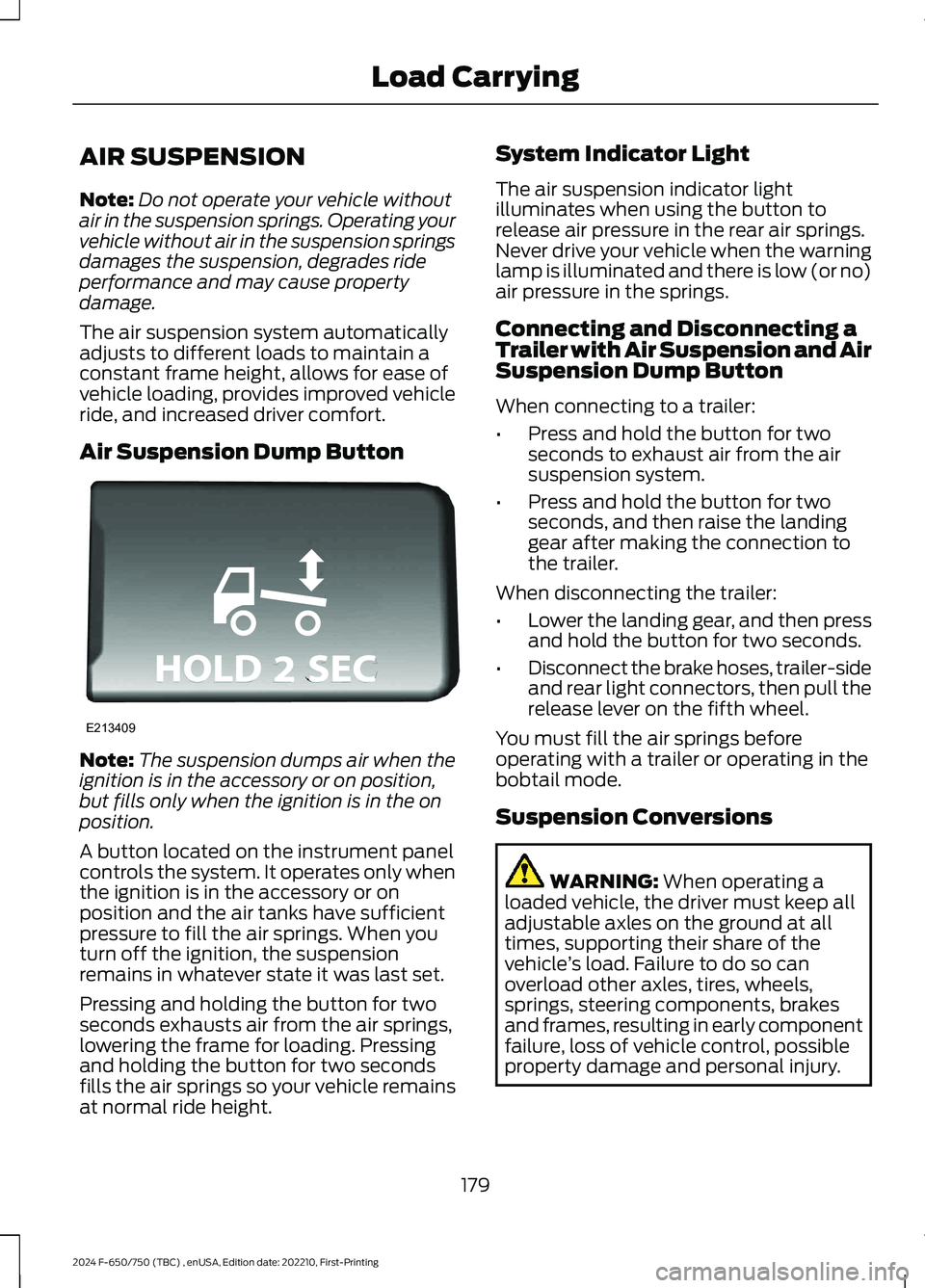
Air Suspension Dump Button
Note:The suspension dumps air when theignition is in the accessory or on position,but fills only when the ignition is in the onposition.
A button located on the instrument panelcontrols the system. It operates only whenthe ignition is in the accessory or onposition and the air tanks have sufficientpressure to fill the air springs. When youturn off the ignition, the suspensionremains in whatever state it was last set.
Pressing and holding the button for twoseconds exhausts air from the air springs,lowering the frame for loading. Pressingand holding the button for two secondsfills the air springs so your vehicle remainsat normal ride height.
System Indicator Light
The air suspension indicator lightilluminates when using the button torelease air pressure in the rear air springs.Never drive your vehicle when the warninglamp is illuminated and there is low (or no)air pressure in the springs.
Connecting and Disconnecting aTrailer with Air Suspension and AirSuspension Dump Button
When connecting to a trailer:
•Press and hold the button for twoseconds to exhaust air from the airsuspension system.
•Press and hold the button for twoseconds, and then raise the landinggear after making the connection tothe trailer.
When disconnecting the trailer:
•Lower the landing gear, and then pressand hold the button for two seconds.
•Disconnect the brake hoses, trailer-sideand rear light connectors, then pull therelease lever on the fifth wheel.
You must fill the air springs beforeoperating with a trailer or operating in thebobtail mode.
Suspension Conversions
WARNING: When operating aloaded vehicle, the driver must keep alladjustable axles on the ground at alltimes, supporting their share of thevehicle’s load. Failure to do so canoverload other axles, tires, wheels,springs, steering components, brakesand frames, resulting in early componentfailure, loss of vehicle control, possibleproperty damage and personal injury.
179
2024 F-650/750 (TBC) , enUSA, Edition date: 202210, First-PrintingLoad CarryingE213409
Page 252 of 386

the driver that battery protection actionsare active. These messages are only fornotification that an action is taking place,and not intended to indicate an electricalproblem or that the battery requiresreplacement.
Electrical accessory installation
To ensure proper operation of the BMS,any electrical devices that are added tothe vehicle should not have their groundconnection made directly at the negativebattery post. A connection at the negativebattery post can cause inaccuratemeasurements of the battery conditionand potential incorrect system operation.
Note:Electrical or electronic accessoriesadded to the vehicle by the dealer or theowner may adversely affect batteryperformance and durability, and may alsoaffect the performance of other electricalsystems in the vehicle.
When a battery replacement is required,the battery should only be replaced witha Ford recommended replacement batterywhich matches the electrical requirementsof the vehicle. After battery replacement,or in some cases after charging the batterywith the external charger, the BMS requireseight hours of vehicle sleep time (key offwith doors closed) to relearn the newbattery state of charge. Prior to relearningthe state of charge, the BMS may disableelectrical features (to protect the battery)earlier than normal.
ADJUSTING THE HEADLAMPS
Vertical Aim Adjustment
The headlamps on your vehicle areproperly aimed at the assembly plant. Ifyour vehicle has been in an accident, thealignment of your headlamps should bechecked by your authorized dealer.
Headlamp Aiming Target
8 ft (2.4 m)A
Center height of lamp to groundB
25 ft (7.6 m)C
Horizontal reference lineD
Vertical Aim Adjustment Procedure
1.Park the vehicle directly in front of awall or screen on a level surface,approximately 25 ft (7.6 m) away.
2.Measure the height of the headlampbulb center from the ground and markan 8 ft (2.4 m) horizontal reference lineon the vertical wall or screen at thisheight.
Note:To see a clearer light pattern foradjusting, you may want to block the lightfrom one headlamp while adjusting theother.
3.Turn on the low beam headlamps toilluminate the wall or screen and openthe hood.
248
2024 F-650/750 (TBC) , enUSA, Edition date: 202210, First-PrintingMaintenanceE142592
Page 264 of 386

•Maintaining proper steering gear andpower steering pump lubricant levels.
•Checking steering column joint boltsand steering linkage, particularly forbody-to-chassis clearance.
Steering Column Joint Bolts
As a good maintenance practice, checksteering column joint bolt tightness every60,000 mi (96,000 km) or annually,whichever occurs first. Do not overtightenthe bolts.
Hydraulic System
Whenever draining and refilling the powersteering's hydraulic system for any reason,bleed air from the system before returningthe vehicle to service. Failure to bleed thehydraulic system properly can result indegradation of power system performance.
Consult an authorized dealer who is awareof the proper procedures for filling andbleeding the system.
SUSPENSION SYSTEM
INSPECTION (IF EQUIPPED)
Note:Do not adjust air suspension heightto any setting other than the specifiedsetting. Altering the height setting changesthe driveline angle and may result inunwarrantable component damage, suchas transmission component damage.
Verify drive axle air suspension height andheight control valve performance at engineoil change intervals.
Periodically check:
•Condition of spring leaves for evidenceof fatigue, bending or breakage.
•Condition of suspension mountingbrackets and bushings.
•Torque rod mounting fasteners fortightness.
•For proper suspension alignment.Maintain proper alignment at all times.
•U-bolts. After the chassis has beenoperating under load for 1,000 mi(1,600 km) or six months (whichevercomes first), the U-bolt nuts must bere-torqued. Re-torque the U-bolt nutsevery 37,000 mi (60,000 km)thereafter. Clean and lubricate theU-bolt and nut threads and seats tomake sure a like new condition whenre-torqueing. See Spring U-BoltCheck (page 261).
FRAME AND TOW HOOK
INSPECTION
Your vehicle's chassis is manufacturedwith frame rails of either HSLA steel orheat-treated steel. Handle each in aspecific manner to make sure maximumservice life. Consult the service manual oran authorized dealer before attemptingframe repair or modification.
It is important, particularly on vehicles thatuse tow hooks frequently, to inspect thefront and rear tow hooks for damage or aloose mounting.
REAR AXLE FLUID CHECK
Your rear axle may have an optionalsynthetic lubricant that allows the use ofextended service intervals. A tag on thefiller plug identifies the use of the syntheticlubricant.
Only use a lubricant that meetsmanufacturer specifications. Use of anon-approved rear axle lubricant maycause internal axle component damage.See Rear Axle Fluid Capacity andSpecification (page 311).
Checking the Fluid Level
1.Park your vehicle on level ground.
260
2024 F-650/750 (TBC) , enUSA, Edition date: 202210, First-PrintingMaintenance
Page 265 of 386

2.Set the parking brake and shift intoposition neutral (N) or park (P). Turnthe engine off.
3.Clean any dirt from around the axlefiller plug.
4.Remove the filler plug and inspect thelubricant level. It should be at thebottom of the filler plug opening.
5.Add lubricant, if necessary, through thefiller plug opening.
6.Clean and install the filler plug securely.
Changing the Fluid
Note:Drain the rear axle while the lubricantis warm.
1.Park your vehicle on level ground.
2.Set the parking brake and shift intoposition neutral (N) or park (P). Turnthe engine off.
3.Clean any dirt from around the axlefiller and drain plugs.
4.Remove the filler and drain plugs. Drainthe lubricant into a suitable container.Dispose of all used automotive fluidsin a responsible manner following yourlocal authorized standards.
5.Clean and install the drain plugsecurely.
6.Add lubricant through the filler plugopening.
7.Clean and install the filler plug securely.
SPRING U-BOLT CHECK
Check and tighten the U-bolt nuts afteryour vehicle has been operated under loadfor 1,000 mi (1,600 km) or six months,whichever occurs first.
Check and tighten the U-bolt nuts every37,000 mi (60,000 km).
Check and tighten the U-bolt nuts withyour vehicle at curb height and unloaded.
Inspect the U-bolt threads for rust anddebris. Clean the threads if contaminated.
U-bolt Nut Torque
Front Axle
Note:Check and tighten the U-bolt nutsevenly using a criss-cross pattern in thefollowing stages.
lb.ft (Nm)Stage
40 (60)1.
90 (125)2.
170 (225)3.
240 (325)4.
Rear Axle
Note:Check and tighten the U-bolt nutsevenly using a criss-cross pattern in thefollowing stages.
lb.ft (Nm)Stage
60 (75)1.
90 (125)2.
170 (225)3.
240 (325)4.
320 (440)5.
261
2024 F-650/750 (TBC) , enUSA, Edition date: 202210, First-PrintingMaintenance