Page 225 of 303

WARNING: Never place anythingbetween the vehicle jack and yourvehicle.
WARNING: Never place anythingbetween the vehicle jack and the ground.
WARNING: Only use the specifiedjacking points. If you use any otherlocations you could damage vehiclecomponents, such as brake lines.
WARNING: Failure to follow theseguidelines could result in an increasedrisk of loss of vehicle control, injury ordeath.
WARNING: Only use the sparewheel carrier to stow wheels providedwith your vehicle.
Note:Passengers should not remain in yourvehicle when the vehicle is being jacked.
Note:Do not use impact tools or powertools operating at over 200 RPM on thespare wheel carrier winch, which may causeit to malfunction and prevent a secure fit.Override the winch at least three times(there is an audible click each time) to makesure the wheel and tire fit securely.
Note:No maintenance or additionallubrication of your jack is required over theservice life of your vehicle.
1.Park the vehicle on a level firm groundand activate the hazard flashers.
2.Apply the parking brake, place thetransmission in park (P), turn theengine off.
3.Block the wheel diagonally oppositethe flat tire. For example, if the leftfront tire is flat, block the right rearwheel.
Removing the Spare Tire
1.To access the spare tire it must belowered from its stowed position.Remove the thumb screw andanti-theft bracket as required. Use thewheel nut wrench tip to loosen it.
2.Guide the wheel nut wrench or jackhandle through the hole and into thetube.
3.Turn the wrench or handlecounterclockwise until the cable hasslack and the tire can be slid rearward.
4.Remove the retainer from the spare tireand remove the spare tire.
221
2024 E-Series (TE4) Canada/United States of America, enUSA, Edition date: 202210, First-PrintingWheels and TiresE166722 E175447
Page 226 of 303
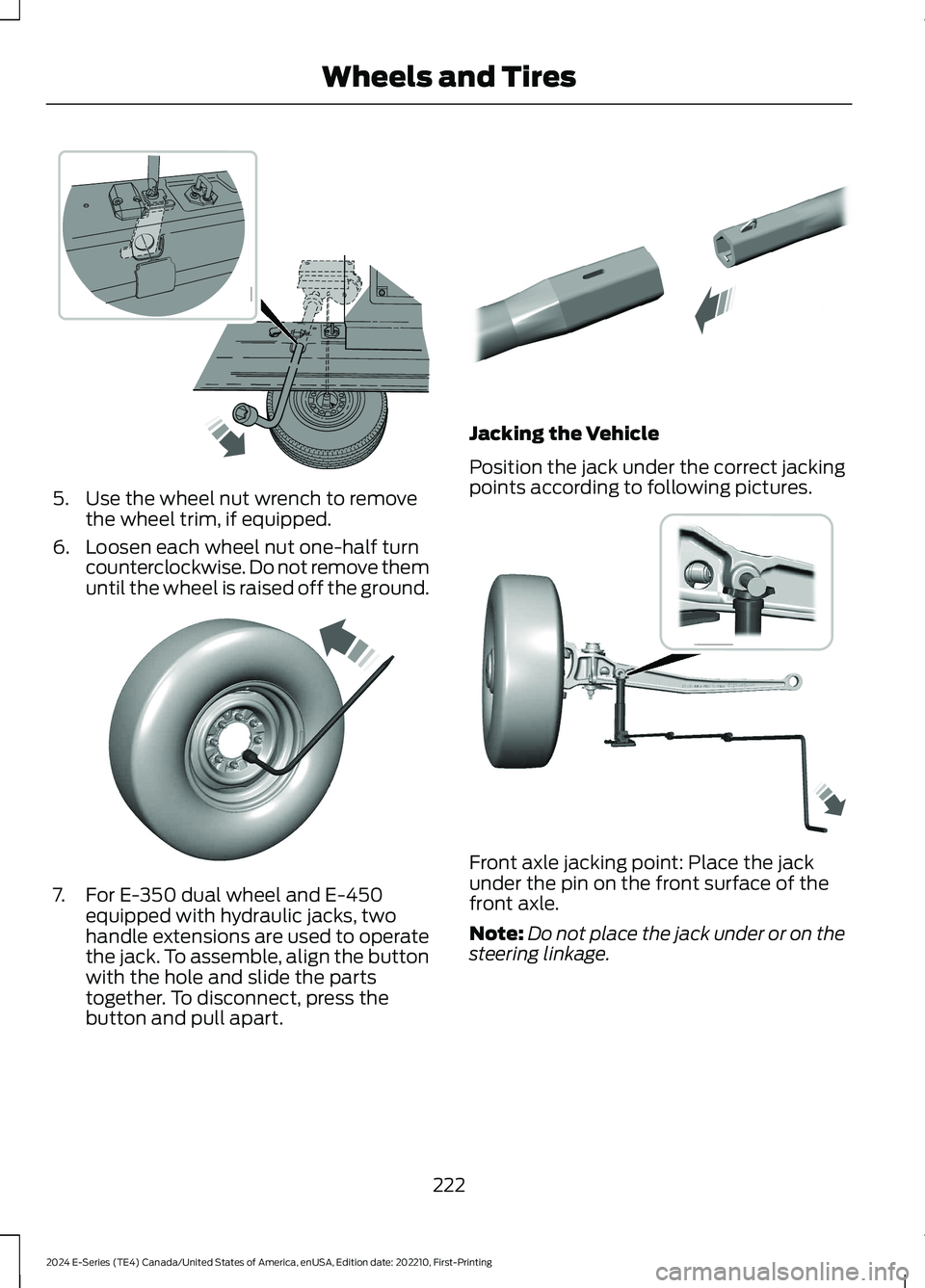
5.Use the wheel nut wrench to removethe wheel trim, if equipped.
6.Loosen each wheel nut one-half turncounterclockwise. Do not remove themuntil the wheel is raised off the ground.
7.For E-350 dual wheel and E-450equipped with hydraulic jacks, twohandle extensions are used to operatethe jack. To assemble, align the buttonwith the hole and slide the partstogether. To disconnect, press thebutton and pull apart.
Jacking the Vehicle
Position the jack under the correct jackingpoints according to following pictures.
Front axle jacking point: Place the jackunder the pin on the front surface of thefront axle.
Note:Do not place the jack under or on thesteering linkage.
222
2024 E-Series (TE4) Canada/United States of America, enUSA, Edition date: 202210, First-PrintingWheels and Tires E366770 E366771 E308882 E366985
Page 227 of 303

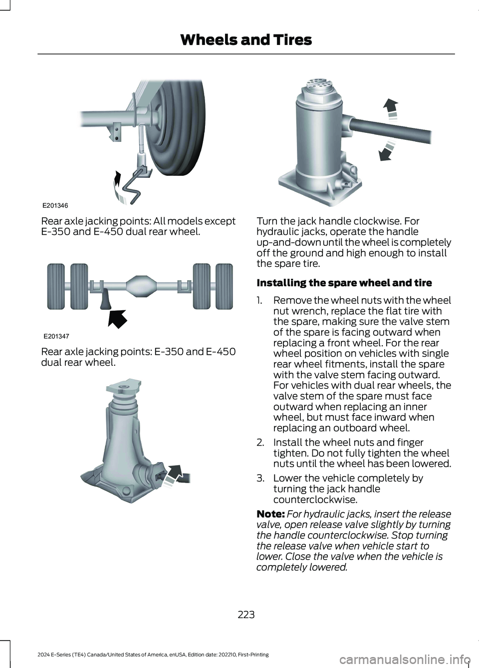
Rear axle jacking points: All models exceptE-350 and E-450 dual rear wheel.
Rear axle jacking points: E-350 and E-450dual rear wheel.
Turn the jack handle clockwise. Forhydraulic jacks, operate the handleup-and-down until the wheel is completelyoff the ground and high enough to installthe spare tire.
Installing the spare wheel and tire
1.Remove the wheel nuts with the wheelnut wrench, replace the flat tire withthe spare, making sure the valve stemof the spare is facing outward whenreplacing a front wheel. For the rearwheel position on vehicles with singlerear wheel fitments, install the sparewith the valve stem facing outward.For vehicles with dual rear wheels, thevalve stem of the spare must faceoutward when replacing an innerwheel, but must face inward whenreplacing an outboard wheel.
2.Install the wheel nuts and fingertighten. Do not fully tighten the wheelnuts until the wheel has been lowered.
3.Lower the vehicle completely byturning the jack handlecounterclockwise.
Note:For hydraulic jacks, insert the releasevalve, open release valve slightly by turningthe handle counterclockwise. Stop turningthe release valve when vehicle start tolower. Close the valve when the vehicle iscompletely lowered.
223
2024 E-Series (TE4) Canada/United States of America, enUSA, Edition date: 202210, First-PrintingWheels and TiresE201346 E201347 E162811 E162819
Page 228 of 303

4.Install the wheel nuts in the sequenceshown.
5.Remove the jack and fully tighten thewheel nuts in the sequence shown. SeeTechnical Specifications (page 225).
6.Install any wheel covers or hubcaps.Make sure they snap into place.
Note:When installing the wheel centerornaments, make sure that the ornamentretention towers on the back side of theornament are aligned with the studs andwheel nuts and retain to the flange on thewheel nuts.
Stowing the Flat tire or Spare tire
1.Place the tire on end with the valvestem facing toward the front of thevehicle. Lay the tire on the ground, nearthe rear of the vehicle, with the valvestem side facing up.
2.Slide the wheel partially under thevehicle and install the retainer throughthe wheel center. If equipped, you mayhave to remove the wheel center capprior to pushing the retainer throughthe center of the wheel. To remove thecenter cap, press it off with the wheelnut wrench tip from the inner side ofthe wheel. Pull on the cable to align thecomponents at the end of the cable.
3.Turn the wheel nut wrench clockwiseuntil the tire is raised to its stowedposition underneath the vehicle. Thewrench becomes harder to turn andthe spare tire winch ratchets or slipswhen the tire is raised to its maximumtightness. A clicking sound is heardfrom the winch indicating that the tireis properly stowed. Check that the tirelies flat against the frame and isproperly tightened.
4.Unblock the wheel.
224
2024 E-Series (TE4) Canada/United States of America, enUSA, Edition date: 202210, First-PrintingWheels and Tires13427658E161441 12345678910E169375 E162800
Page 229 of 303

TECHNICAL SPECIFICATIONS
Wheel Lug Nut Torque Specifications
WARNING: When you install a wheel, remove any corrosion, dirt or foreign materialspresent on the mounting surfaces of the wheel or the surface of the wheel hub, brakedrum or brake disc that contacts the wheel. Make sure to secure any fasteners thatattach the rotor to the hub so they do not interfere with the mounting surfaces of thewheel. Installing wheels without following these steps can cause the wheel nuts toloosen and the wheel to come off while your vehicle is in motion, resulting in loss ofvehicle control, personal injury or death.
lb.ft (Nm)1Bolt size
140 lb.ft (190 Nm)9/16 x 18 two-piece lug nut
1 Torque specifications are for nut and bolt threads free of dirt and rust. Use only Fordrecommended replacement fasteners.
On vehicles equipped with single rear wheels, retighten the lug nuts to the specified torqueat 100 miles (160 kilometers) after any wheel disturbance (such as tire rotation, changinga flat tire, wheel removal).
On vehicles equipped with dual rear wheels, retighten the wheel lug nuts to the specifiedtorque at 100 miles (160 kilometers), and again at 500 miles (800 kilometers) of newvehicle operation and after any wheel disturbance (such as tire rotation, changing a flattire, wheel removal).
On all two-piece flat wheel nuts,apply one drop of motor oilbetween the flat washer and thenut. Do not apply motor oil to thewheel nut threads or the wheelstud threads.
Wheel pilot boreA
Inspect the wheel pilot hole andmounting surface prior to installation.Remove any visible corrosion or looseparticles.
225
2024 E-Series (TE4) Canada/United States of America, enUSA, Edition date: 202210, First-PrintingWheels and TiresE161443 E145950
Page 230 of 303
ENGINE SPECIFICATIONS
7.3L V8 EngineEngine
445 in³ (7,293 cm³)Displacement.
Minimum 87 octaneRequired fuel.
1-5-4-8-6-3-7-2Firing order.
Coil near spark plug with spark plug wireIgnition system.
0.049 in (1.25 mm) - 0.053 in (1.35 mm)Spark plug gap.
10.5:1Compression ratio.
Drivebelt Routing
Single Alternator
Drivebelt closest to the engine.A
Drivebelt furthest from theengine.B
Dual Alternator
Drivebelt closest to the engine.A
Drivebelt furthest from theengine.B
226
2024 E-Series (TE4) Canada/United States of America, enUSA, Edition date: 202210, First-PrintingCapacities and SpecificationsE388771 E388772
Page 231 of 303
MOTORCRAFT PARTS - 7.3L
Motorcraft Part numberComponent
FA-2042Air filter element.
BXT-65-750One battery.
BXT-65-750Two batteries (optional).
FL-820-SEngine oil filter.1
SP-589Spark plug.
FT-187Transmission fluid filter.
WW-2005Windshield wiper blade.
1 If a Motorcraft oil filter is not available, use an oil filter that aligns to SAE/USCAR – 36Performance Specifications. Filter Type D.
We recommend Motorcraft parts that are available at your authorized dealer or atwww.fordparts.com. We engineer these parts for your vehicle to meet or exceed ourspecifications. Use of other parts could impact vehicle performance, emissions anddurability. Your warranty could be void for any damage related to use of other parts.
227
2024 E-Series (TE4) Canada/United States of America, enUSA, Edition date: 202210, First-PrintingCapacities and Specifications
Page 232 of 303
BULB SPECIFICATION CHART
Replacement bulbs are specified in thechart below. Headlamp bulbs must bemarked with an authorized “D.O.T.” for
North America and an “E” for Europe toensure lamp performance, light brightnessand pattern and safe visibility. The correctbulbs will not damage the lamp assemblyor void the lamp assembly warranty andwill provide quality bulb illumination time.
Exterior Lamps
Trade NameLamp
W5WFront side marker lamp.
3157AKPark lamp.
3157AKFront direction indicator.
H13Headlamp low beam.
H13Headlamp high beam.
2825Front clearance lamp (exterior mirror).
3157KBrake, rear and direction indicator lamp.
3156Reversing lamps.
Interior Lamps
Trade NameLamp
906Underhood Lamp.
578Map lamp.
578Dome lamp.
578Cargo lamp.
To replace all instrument panel lights - see your authorized dealer.
228
2024 E-Series (TE4) Canada/United States of America, enUSA, Edition date: 202210, First-PrintingCapacities and Specifications