2023 TOYOTA VENZA HYBRID instrument panel
[x] Cancel search: instrument panelPage 17 of 560
17Pictorial index
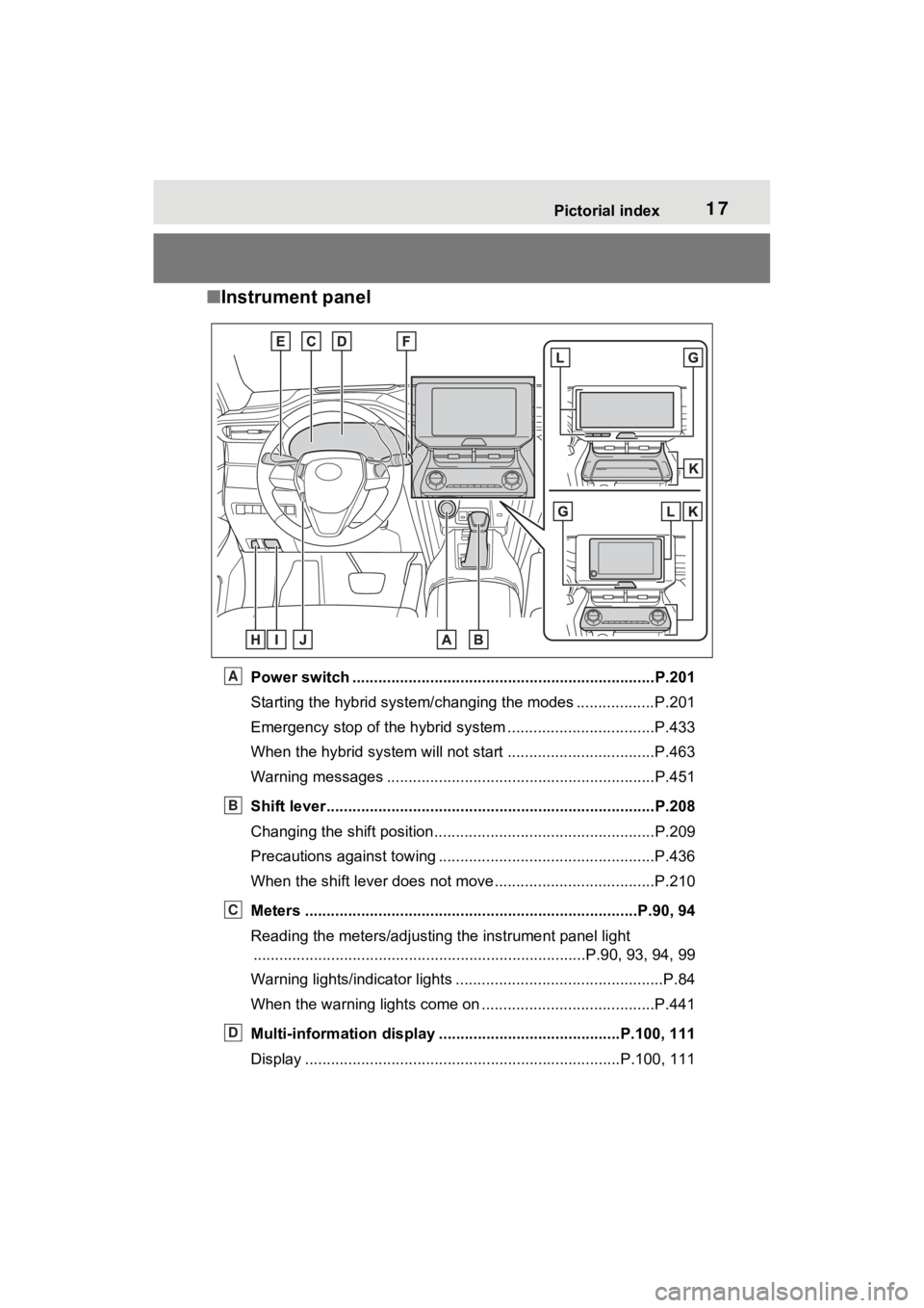
■Instrument panel
Power switch ................................................... ...................P.201
Starting the hybrid system/changing the modes .................. P.201
Emergency stop of the hybrid system ............................ ......P.433
When the hybrid system will not start .......................... ........P.463
Warning messages ..............................................................P.451
Shift lever.................................................... ........................P.208
Changing the shift position.................................... ...............P.209
Precautions against towing ..................................................P.436
When the shift lever does not move............................. ........P.210
Meters ......................................................... ....................P.90, 94
Reading the meters/adjusting the instrument panel light ............................................................... ..............P.90, 93, 94, 99
Warning lights/indicator lights ................................ ................P.84
When the warning lights come on ................................ ........P.441
Multi-information display . .........................................P.100, 111
Display ........................................................ .................P.100, 111A
B
C
D
Page 19 of 560
19Pictorial index
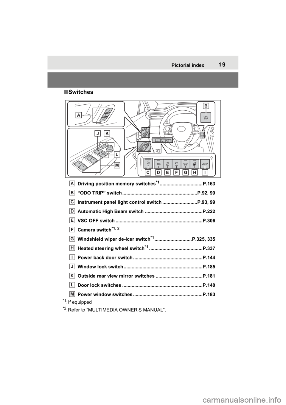
■Switches
Driving position memory switches*1................................P.163
“ODO TRIP” switch .............................................. ..........P.92, 99
Instrument panel light cont rol switch ..........................P.93, 99
Automatic High Beam switch ..................................... ......P.222
VSC OFF switch .................................................................P.306
Camera switch
*1, 2
Windshield wiper de-icer switch*1............................P.325, 335
Heated steering wheel switch
*1........................................P.337
Power back door switch ... .................................................P.144
Window lock switch ............................................. ..............P.185
Outside rear view mirror swi tches ...................................P.181
Door lock switches ............................................................P.140
Power window switches ....... .............................................P.183
*1: If equipped
*2: Refer to “MULTIMEDIA OWNER’S MANUAL”.
A
B
C
D
E
F
G
H
I
J
K
L
M
Page 38 of 560
381-1. For safe use
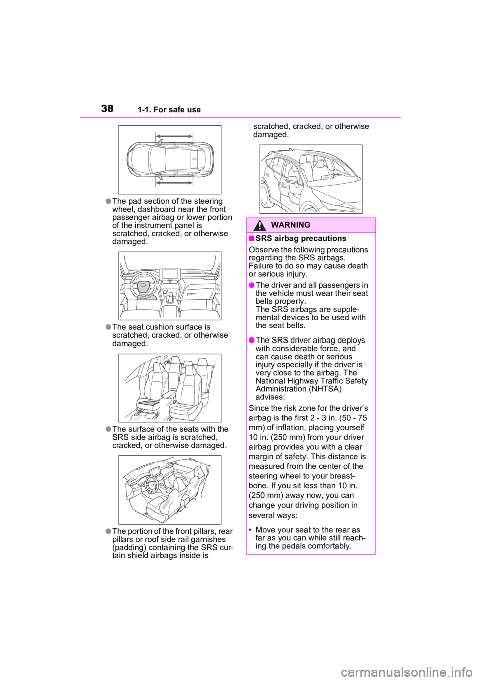
●The pad section of the steering
wheel, dashboard near the front
passenger airbag or lower portion
of the instrument panel is
scratched, cracked, or otherwise
damaged.
●The seat cushion surface is
scratched, cracked, or otherwise
damaged.
●The surface of the seats with the
SRS side airbag is scratched,
cracked, or otherwise damaged.
●The portion of the front pillars, rear
pillars or roof side rail garnishes
(padding) containing the SRS cur-
tain shield airbags inside is scratched, cracked, or otherwise
damaged.
WARNING
■SRS airbag precautions
Observe the following precautions
regarding the SRS airbags.
Failure to do so may cause death
or serious injury.
●The driver and all passengers in
the vehicle must wear their seat
belts properly.
The SRS airbags are supple-
mental devices to be used with
the seat belts.
●The SRS driver airbag deploys
with considerable force, and
can cause death or serious
injury especially if the driver is
very close to the airbag. The
National Highway Traffic Safety
Administration (NHTSA)
advises:
Since the risk zone for the driver’s
airbag is the first 2 - 3 in. (50 - 75
mm) of inflation, placing yourself
10 in. (250 mm) from your driver
airbag provides you with a clear
margin of safety. This distance is
measured from the center of the
steering wheel to your breast-
bone. If you sit less than 10 in.
(250 mm) away now, you can
change your driving position in
several ways:
• Move your seat to the rear as far as you can while still reach-
ing the pedals comfortably.
Page 40 of 560
401-1. For safe use
WARNING
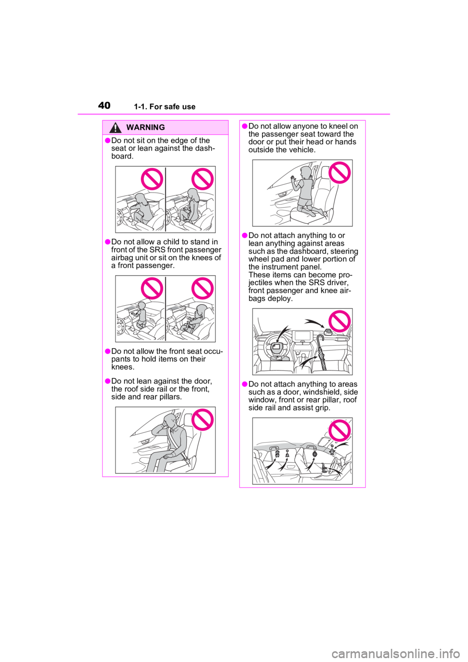
●Do not sit on the edge of the
seat or lean against the dash-
board.
●Do not allow a child to stand in
front of the SRS front passenger
airbag unit or sit on the knees of
a front passenger.
●Do not allow the front seat occu-
pants to hold items on their
knees.
●Do not lean against the door,
the roof side rail or the front,
side and rear pillars.
●Do not allow anyone to kneel on
the passenger seat toward the
door or put their head or hands
outside the vehicle.
●Do not attach anything to or
lean anything against areas
such as the dashboard, steering
wheel pad and lower portion of
the instrument panel.
These items can become pro-
jectiles when the SRS driver,
front passenger and knee air-
bags deploy.
●Do not attach anything to areas
such as a door, windshield, side
window, front or rear pillar, roof
side rail and assist grip.
Page 41 of 560
411-1. For safe use
1
For safety and security
WARNING
●Do not hang coat hangers or
other hard objects on the coat
hooks. All of these items could
become projectiles and may
cause death or serious injury,
should the SRS curtain shield
airbags deploy.
●If a vinyl cover is put on the area
where the SRS knee airbag will
deploy, be sure to remove it.
●Do not use seat accessories
which cover the parts where the
SRS side airbags and SRS seat
cushion airbag inflate as they
may interfere with inflation of
the SRS airbags. Such acces-
sories may prevent the SRS
side airbags and SRS seat
cushion airbag from activating
correctly, disable the system or
cause the SRS side airbags and
SRS seat cushion airbag to
inflate accidentally, resulting in
death or serious injury.
●Do not strike or apply significant
levels of force to the area of the
SRS airbag components or the
front doors.
Doing so can cause the SRS
airbags to malfunction.
●Do not touch any of the compo-
nent parts immediately after the
SRS airbags have deployed
(inflated) as they may be hot.
●If breathing becomes difficult
after the SRS airbags have
deployed, open a door or win-
dow to allow fresh air in, or
leave the vehicle if it is safe to
do so. Wash off any residue as
soon as possible to prevent skin
irritation.
●If the areas where the SRS air-
bags are stored, such as the
steering wheel pad and front
and rear pillar garnishes, are
damaged or cracked, have
them replaced by your Toyota
dealer.
●Do not place anything, such as
a cushion, on the front passen-
ger’s seat. Doing so will
disperse the passenger’s
weight, which prevents the sen-
sor from detecting the passen-
ger’s weight properly. As a
result, the SRS front airbags for
the front passenger may not
deploy in the event of a colli-
sion.
■Modification and disposal of
SRS airbag system compo-
nents
Do not dispose of your vehicle or
perform any of the following modi-
fications without consulting your
Toyota dealer. The SRS airbags
may malfunction or deploy
(inflate) accidentally, causing
death or serious injury.
●Installation, re moval, disassem-
bly and repair of the SRS air-
bags
●Repairs, modific ations, removal
or replacement of the steering
wheel, instrument panel, dash-
board, seats or seat upholstery,
front, side and rear pillars, roof
side rails, front door panels,
front door trims or front door
speakers
●Modifications to the front door
panel (such as making a hole in
it)
●Repairs or modifications of the
front fender, fr ont bumper, or
side of the occupant compart-
ment
Page 84 of 560
842-1. Instrument cluster
2-1.Instrument cluster
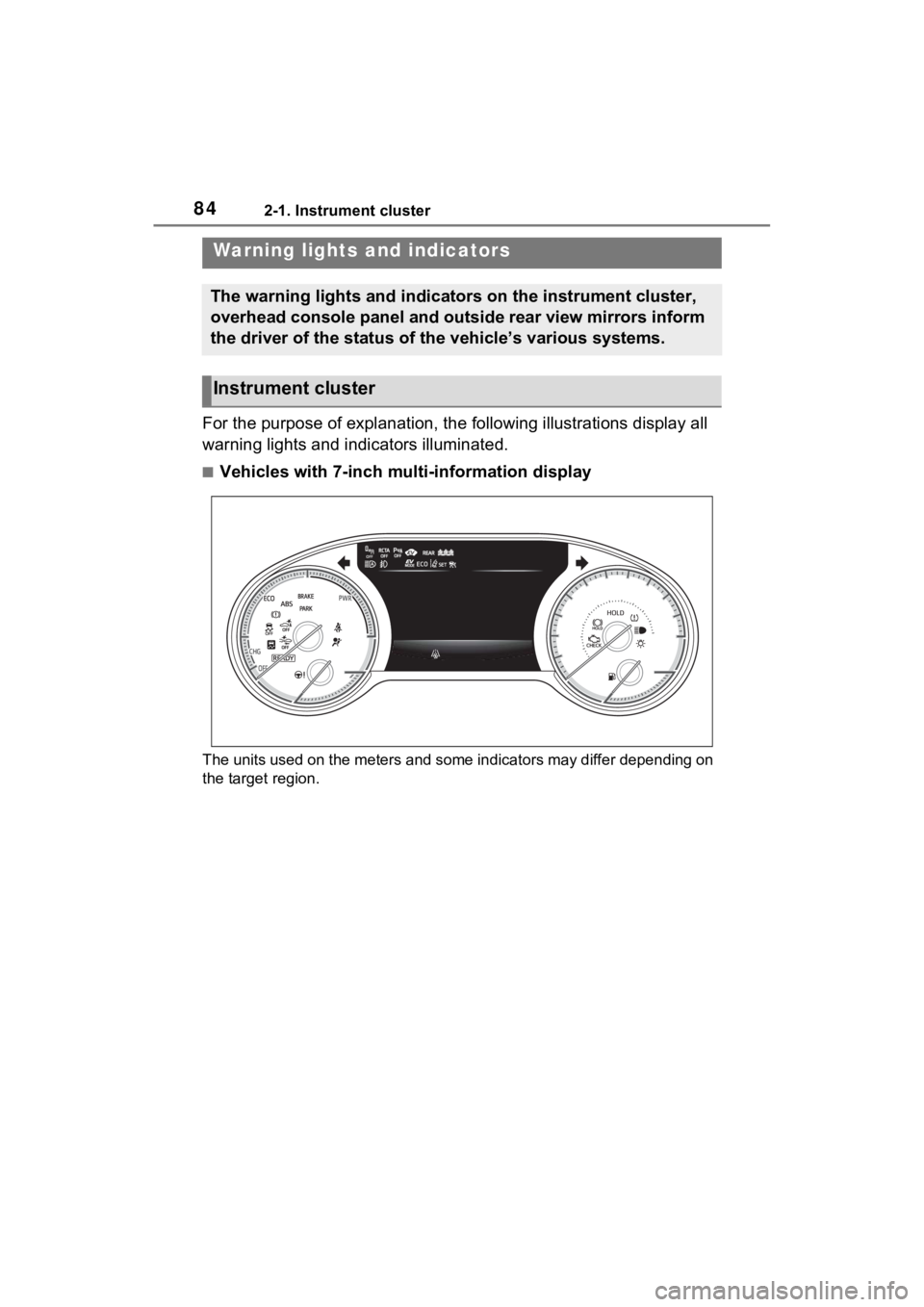
For the purpose of explanation, the following illustrations display all
warning lights and indicators illuminated.
■Vehicles with 7-inch multi-information display
The units used on the meters and some indicators may differ dep ending on
the target region.
Warning lights and indicators
The warning lights and indicators on the instrument cluster,
overhead console panel and outside rear view mirrors inform
the driver of the status of the vehicle’s various systems.
Instrument cluster
Page 89 of 560

892-1. Instrument cluster
2
Vehicle status information and indicators
*1: This light illuminates on the multi-informatio n display with a
message.
*2: Depending on the operating con- dition, the color and illuminat-
ing/flashing state of the light
change.
*3: The light comes on when the system is turned off.
*4: Intuitive parking assist OFF indi-cator turns on when the power
switch is turned to ON while the
Intuitive parking assist function is
on. It will turn off after a few sec-
onds.
*5: These lights turn on when the power switch is turned to ON to
indicate that a system check is
being performed. They will turn
off after the hybr id system is on,
or after a few seconds. There
may be a malfunction in a sys-
tem if the lights do not turn on, or
turn off. Have the vehicle
inspected by your Toyota dealer.
*6: This light illumi nates on the out-
side rear view mirrors.
*7: This light illuminates on the over- head console panel.
*8: When the outside temperature is approximately 37°F (3°C) or
lower, the indicator will flash for approximately 10 seconds, then
stay on.
■BSM (Blind Spot Monitor) out-
side rear view mirror indicators
In order to confirm operation, the
BSM outside rear view mirror indica-
tors illuminate in the turning the
BSM function/RCTA function on
( P.278).
If the system is functioning correctly,
the BSM outside rear view mirror
indicators will turn off after a few
seconds.
If the BSM outside rear view mirror
indicators do not illuminate or do not
turn off, there may be a malfunction
in the system. If this occurs, have
the vehicle inspected by your
Toyota dealer.
EV drive mode indicator
(
P.206)
Eco drive mode indicator
( P.304)
Sport mode indicator
( P.304)
“AIR BAG ON/OFF”
indicator
*5, 7 ( P.43)
Page 93 of 560
932-1. Instrument cluster
2
Vehicle status information and indicators
When the trip meter is displayed,
pressing and holding the switch will
reset the trip meter.
Distance until next engine oil
change
Displays the distan ce the vehicle
can be driven until an oil change is
necessary.
■Changing the display
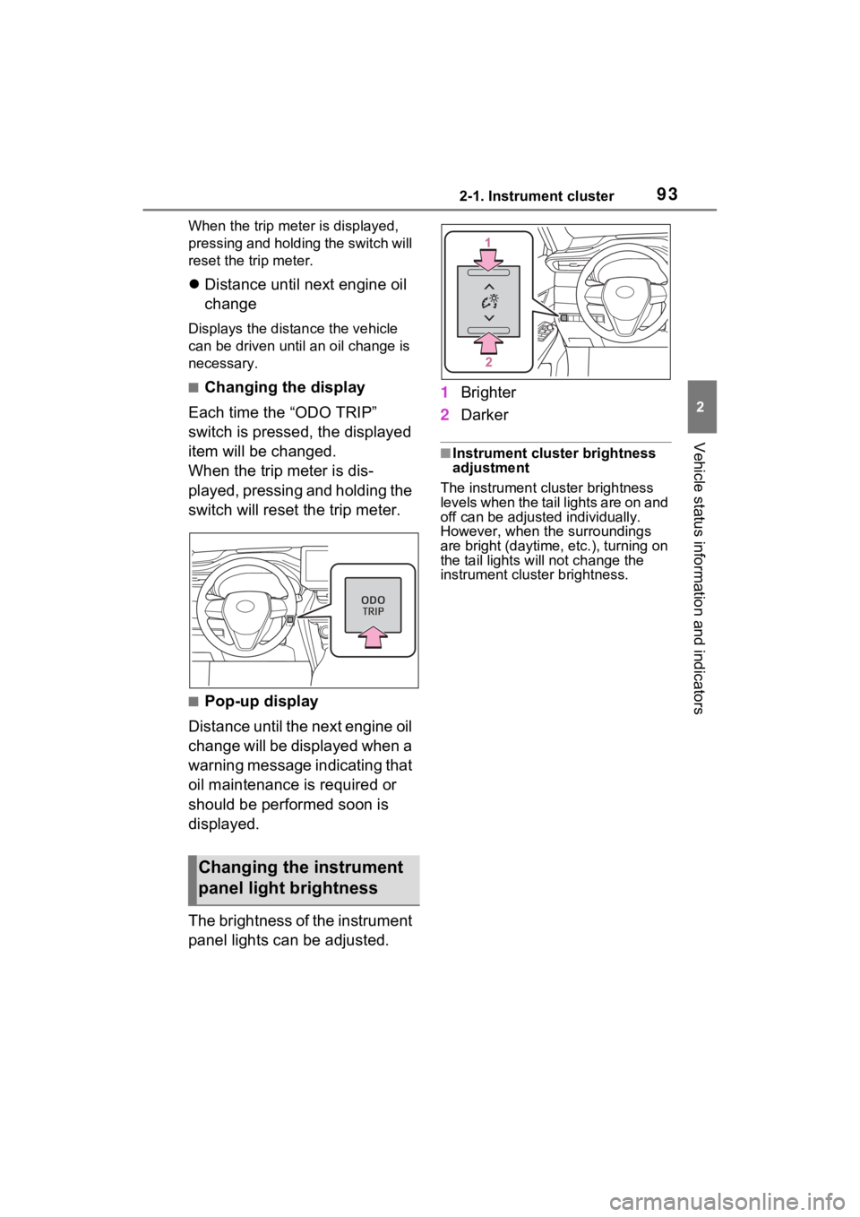
Each time the “ODO TRIP”
switch is pressed, the displayed
item will be changed.
When the trip meter is dis-
played, pressing and holding the
switch will reset the trip meter.
■Pop-up display
Distance until the next engine oil
change will be displayed when a
warning message indicating that
oil maintenance is required or
should be performed soon is
displayed.
The brightness of the instrument
panel lights can be adjusted. 1
Brighter
2 Darker
■Instrument cluster brightness
adjustment
The instrument cluster brightness
levels when the tail lights are on and
off can be adjusted individually.
However, when the surroundings
are bright (daytime, etc.), turning on
the tail lights will not change the
instrument cluster brightness.
Changing the instrument
panel light brightness