2023 TOYOTA TUNDRA HYBRID display
[x] Cancel search: displayPage 383 of 618
3834-5. Using the driving support systems
Owners Manual_USA_M0C052_en
4
Driving
“Trailer Direction”
When using Straight Path Assist,
the driver can override the system
using the steering wheel to adjust
the trailer direction. Upon release of
the steering wheel, Straight Path
Assist re-activates with a revised
straight back target direction.
■When adding the trailer
Use the meter control switches to
select the trailer type. ( P. 9 6 )
1 Press or to select .
2 Press or to select “Trailer
Settings” and then press and
hold .
3 According to the display, select
the desired setting and then
press . ( P.100)
Trailer Settings are not available
while Trailer Backup Guide system
is active.
The system is designed to support
trailers with single or multi-axles
using a ball hitch. The system does
not support fifth wheel or gooseneck
trailers.
Bring the vehicle and trailer to a
large open space like an empty
parking lot. Activate Trailer
Backup Guide system and fol-
low the instructions displayed on
the multi-information dis-
play/multimedia.
For best calibration results, do
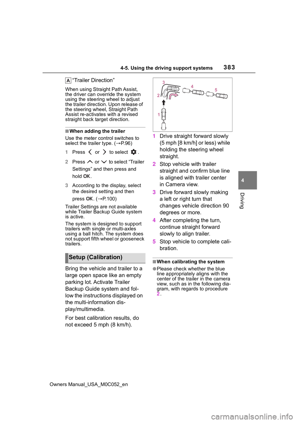
not exceed 5 mph (8 km/h). 1
Drive straight forward slowly
(5 mph [8 km/h] or less) while
holding the steering wheel
straight.
2 Stop vehicle with trailer
straight and confirm blue line
is aligned with trailer center
in Camera view.
3 Drive forward slowly making
a left or right turn that
changes vehicle direction 90
degrees or more.
4 After completing the turn,
continue straight forward
slowly to align trailer.
5 Stop vehicle to complete cali-
bration.
■When calibrating the system
●Please check whether the blue
line appropriately aligns with the
center of the trailer in the camera
view, such as in the following dia-
gram, with regards to procedure
2 .
Setup (Calibration)
Page 384 of 618
3844-5. Using the driving support systems
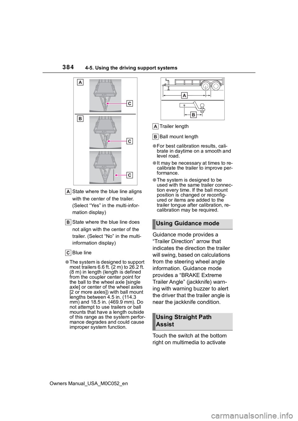
Owners Manual_USA_M0C052_enState where the blue line aligns
with the center of the trailer.
(Select “Yes” in the multi-infor-
mation display)
State where the blue line does
not align with the center of the
trailer. (Select “
No” in the multi-
information display)
Blue line
●The system is designed to support
most trailers 6.6 ft. (2 m) to 26.2 ft.
(8 m) in length (length is defined
from the coupler c enter point for
the ball to the wheel axle [single
axle] or center o f the wheel axles
[2 or more axles]) with ball mount
lengths between 4.5 in. (114.3
mm) and 18.5 in. ( 469.9 mm). Do
not attempt to use trailers or ball
mounts that have a length outside
of this range as t he system perfor-
mance degrades and could cause
improper system function. Trailer length
Ball mount length
●For best calibration results, cali-
brate in daytime on a smooth and
level road.
●It may be necessary at times to re-
calibrate the trailer to improve per-
formance.
●The system is designed to be
used with the same trailer connec-
tion every time. If the ball mount
position is changed or reconfig-
ured or items are added to the
trailer tongue
after calibration, re-
calibration may be required.
Guidance mode provides a
“Trailer Direction” arrow that
indicates the direction the trailer
will swing, based on calculations
from the steering wheel angle
information. Guidance mode
provides a “BRAKE Extreme
Trailer Angle” (jackknife) warn-
ing with warning buzzer to alert
the driver that the trailer angle is
near the jackknife condition.
Touch the switch at the bottom
right on multimedia to activate
Using Guidance mode
Using Straight Path
Assist
Page 422 of 618
4245-4. Using the other interior features
Owners Manual_USA_M0C052_en
WARNING
■Caution regarding interfer-
ence with electronic devices
People with implantable cardiac
pacemakers, cardiac resynchroni-
zation therapy-pacemakers or
implantable cardioverter defibrilla-
tors, as well as any other electri-
cal medical device, should consult
their physician about the usage of
the wireless charger. The opera-
tions of the wireless charger may
have an affect on medical
devices.
■To prevent damage or burns
Observe the following precau-
tions.
Failure to do so m ay result in a
possibility of equ ipment failure
and damage, catch fire, burns due
to overheat.
●Do not insert any metallic
objects between the charging
area and the portable device
while charging
●Do not attach stickers, metallic
objects, etc., to the charger area
or portable device
●Do not cover with cloth, etc.,
and charge
●Do not charge portable devices
other than designated
●Do not attempt t o dismantle for
disassembly or modifications
●Do not hit or apply a strong
force
NOTICE
■Conditions in which the func-
tion may not operate cor-
rectly
In the following co nditions, it may
not operate correctly
●The portable device is fully
charged
●There is foreign matter between
the charge area and portable
device
●The temperature of the portable
device gets higher from
charging
●The charging surface of the por-
table device is facing up
●The placement of the portable
device is out of alignment with
the charge area
●Near a TV tower, electric power
plant, gas station, radio station,
large display, a irport or other
facility that gen erates strong
radio waves or electrical noise
●When the portable device is in
contact with, or is covered by
the following metallic objects
• Cards to which aluminum foil is attached
• Cigarette boxes that have alu- minum foil inside
• Metallic wallets or bags
• Coins
• Hand warmers made of metal
• Media such as CDs and DVDs
Page 423 of 618
4255-4. Using the other interior features
Owners Manual_USA_M0C052_en
5
Interior features
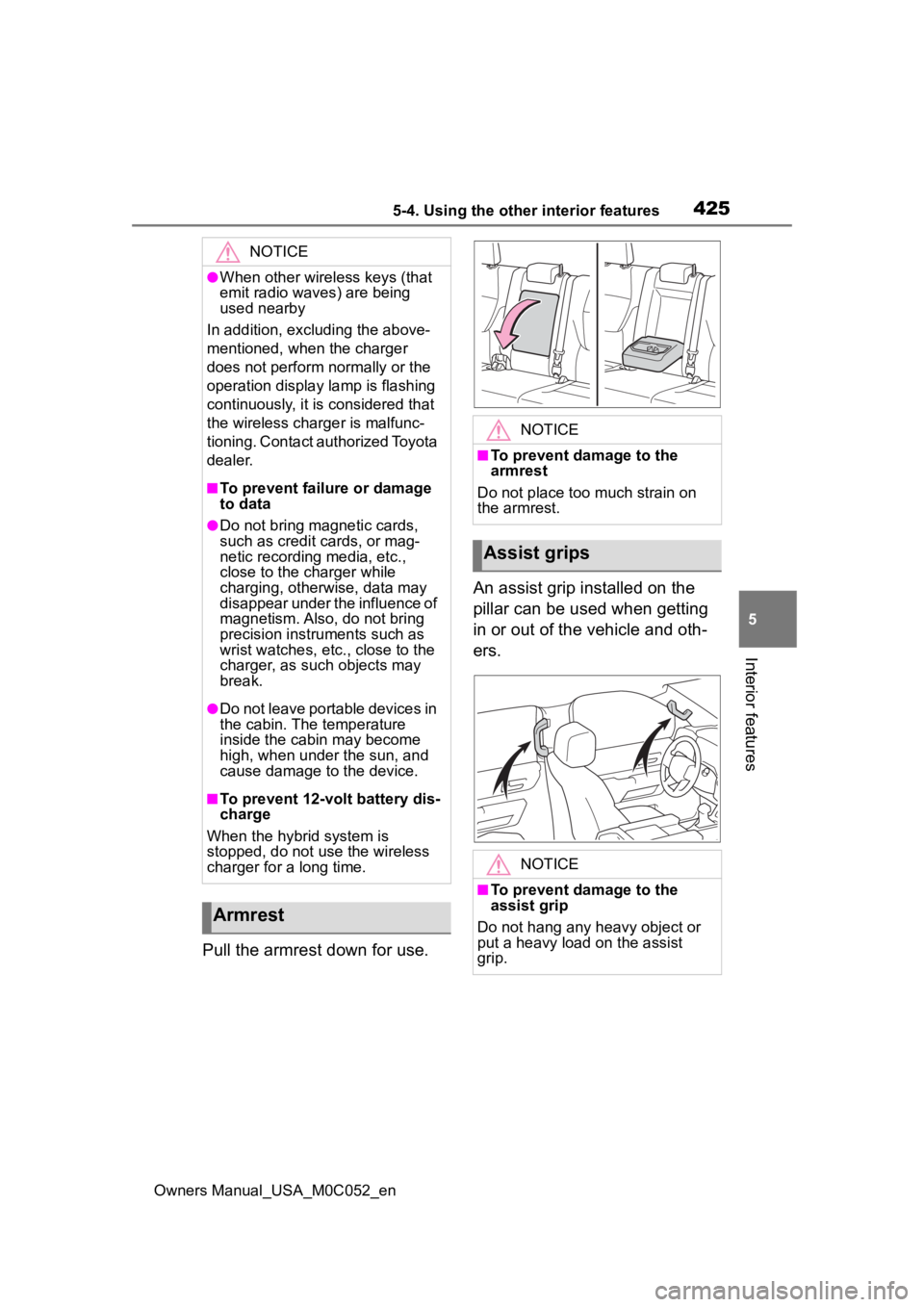
Pull the armrest down for use. An assist grip installed on the
pillar can be used when getting
in or out of the vehicle and oth-
ers.
NOTICE
●When other wireless keys (that
emit radio waves) are being
used nearby
In addition, excl uding the above-
mentioned, when the charger
does not perform normally or the
operation display lamp is flashing
continuously, it is considered that
the wireless charger is malfunc-
tioning. Contact authorized Toyota
dealer.
■To prevent failu re or damage
to data
●Do not bring magnetic cards,
such as credit cards, or mag-
netic recording media, etc.,
close to the charger while
charging, otherwise, data may
disappear under the influence of
magnetism. Also, do not bring
precision instruments such as
wrist watches, etc ., close to the
charger, as such objects may
break.
●Do not leave portable devices in
the cabin. The temperature
inside the cabin may become
high, when under the sun, and
cause damage to the device.
■To prevent 12-volt battery dis-
charge
When the hybrid system is
stopped, do not use the wireless
charger for a long time.
Armrest
NOTICE
■To prevent damage to the
armrest
Do not place too much strain on
the armrest.
Assist grips
NOTICE
■To prevent damage to the
assist grip
Do not hang any heavy object or
put a heavy load on the assist
grip.
Page 433 of 618
4355-4. Using the other interior features
Owners Manual_USA_M0C052_en
5
Interior features
you may need a stepladder or
other sturdy, safe device to
reach the “Learn” or “Smart”
button on the garage door
opener motor.
■Programming HomeLink®
Steps 2 through 4 must be per-
formed within 60 seconds, oth-
erwise the indicator light will
stop flashing and programming
will not be successfully com-
pleted.
1 Vehicles with Digital Rear-
view Mirror: Press the Home-
Link
® button or menu button
When the HomeLink
® button
is pressed: Homelink
® Train-
ing Tutorial will be displayed
to assist you programming
the HomeLink
®.
When the menu button is pressed:
Press the menu button and
select the “SET UP”. Homelink
®
Training Tutorial will be displayed to
assist you programming the Home-
Link
®.
2 Press and release the Home-
Link
® button you want to pro-
gram and check that the
HomeLink
® indicator light
flashes (orange).
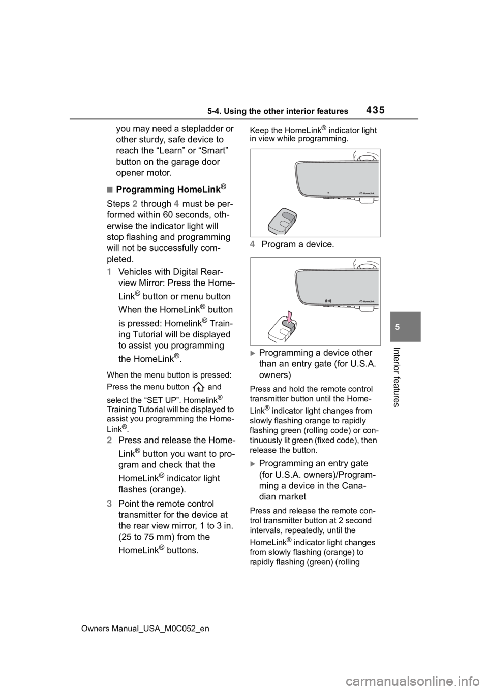
3 Point the remote control
transmitter for the device at
the rear view mirror, 1 to 3 in.
(25 to 75 mm) from the
HomeLink
® buttons.
Keep the HomeLink® indicator light
in view while programming.
4 Program a device.
Programming a device other
than an entry gate (for U.S.A.
owners)
Press and hold the remote control
transmitter button until the Home-
Link
® indicator light changes from
slowly flashing orange to rapidly
flashing green (rolling code) or con-
tinuously lit green (fixed code), then
release the button.
Programming an entry gate
(for U.S.A. owners)/Program-
ming a device in the Cana-
dian market
Press and release the remote con-
trol transmitter button at 2 second
intervals, repeatedly, until the
HomeLink
® indicator light changes
from slowly flashing (orange) to
rapidly flashing (green) (rolling
Page 447 of 618
4496-2. Maintenance
Owners Manual_USA_M0C052_en
6
Maintenance and care
■Resetting the message indicat-
ing maintenance is required
After the required maintenance is
performed according to the mainte-
nance schedule, please reset the
message.
To reset the messa ge, follow the
procedure described below:
1 Press or of meter control
switches and select on the
multi-information display.
2 Press or of meter control
switches and select “Vehicle Set-
tings”, and then press and hold
.
3 Press or of meter control
switches and select “Scheduled
Maintenance”, and then press
.
4 Select the “Yes” and press .
You can perform some mainte-
nance procedures by yourself.
Please be aware that do-it-your-
self maintenance may affect
warranty coverage.
The use of Toyota repair manuals is
recommended.
For details about warranty cover-
age, refer to the separate “Owner’s
Warranty Information Booklet” or
“Owner’s Manual Supplement”.
Do-it-yourself mainte-
nance
General maintenance
Listed below are the general
maintenance items that
should be performed at the
intervals specified in the
“Owner’s Warranty Informa-
tion Booklet” or “Owner’s
Manual Supplement/Sched-
uled Maintenance Guide”. It
is recommended that any
problem you notice should
be brought to the attention
of your Toyota dealer or
qualified service shop for
advice.
WARNING
■If the hybrid system is operat-
ing
Turn the hybrid system off and
ensure that there is adequate
ventilation before performing
maintenance checks.
Engine compartment
ItemsCheck points
Brake fluid
Is the brake fluid at
the correct level?
( P.461)
Engine/inter-
cooler/power
control unit
coolantIs the engine/inter-
cooler/power con-
trol unit coolant at
the correct level?
( P.460)
Engine oil
Is the engine oil at
the correct level?
( P.458)
Page 453 of 618

4556-3. Do-it-yourself maintenance
Owners Manual_USA_M0C052_en
6
Maintenance and care
Light bulbs
( P.490)
• Bulb with same
number and
wattage rating as
original
• Phillips-head screwdriver
• Wrench
Radiator and
condenser
( P.461)
Tire inflation
pressure
( P.476)• Tire pressure
gauge
• Compressed air source
Washer fluid
( P.462)
• Water or washer
fluid containing
antifreeze (for
winter use)
• Funnel (used only for adding
water or washer
fluid)
WARNING
The engine compartment contains
many mechanisms and fluids that
may move suddenly, become hot,
or become electrically energized.
To avoid death or serious injury,
observe the following precautions.
■When working on the engine
compartment
●Make sure that the “ACCES-
SORY” or “IGNITION ON” on
the multi-inform ation display
and the “READY” indicator are
both off.
●Keep hands, clothing and tools
away from the moving fan and
engine.
ItemsParts and tools●Be careful not to touch the
engine, inverter, radiator,
exhaust manifold, etc., right
after driving as they may be hot.
Oil and other fluids may also be
hot.
●Do not leave anything that may
burn easily, such as paper and
rags, in the engine compart-
ment.
●Do not smoke, cause sparks or
expose an open flame to fuel.
■When working near the elec-
tric cooling fan or radiator
grille
Be sure the power switch is off.
With the power switch in ON, the
electric cooling fa n may automati-
cally start to run if the air condi-
tioning is on and/or the coolant
temperature is high. ( P.461)
■Safety glasses
Wear safety glasses to prevent
flying or falling material, fluid
spray, etc., from getting in your
eyes.
NOTICE
■If you remove the air cleaner
filter
Driving with the air cleaner filter
removed may cause excessive
engine wear due to dirt in the air.
Page 457 of 618

4596-3. Do-it-yourself maintenance
Owners Manual_USA_M0C052_en
6
Maintenance and care
Items
Clean funnel
■Adding engine oil
If the oil level is below or near
the low level mark, add engine
oil of the same type as that
already in the engine.
1 Remove the oil filler cap by
turning it counterclockwise.
2 Add engine oil slowly, check-
ing the dipstick.
3 Install the oil filler cap by
turning it clockwise.
■Engine oil consumption
A certain amount of engine oil will
be consumed while driving. In the
following situatio ns, oil consump-
tion may increase, and engine oil
may need to be ref illed in between
oil maintenance intervals.
●When the engine is new, for
example directly after purchasing
the vehicle or after replacing the
engine
●If low quality oil or oil of an inap-
propriate viscosity is used
●When driving at high engine
speeds or with a heavy load,
when towing, or when driving
while accelerating o r decelerating
frequently
●When leaving the engine idling for a long time, or when driving fre-
quently through heavy traffic
■After changing the engine oil
The engine oil maintenance data
should be reset. Pe rform the follow-
ing procedures:
1 Press or of the meter
control switches and select .
2 Press or of the meter
control switches, select the
“Vehicle Settings” and then press
.
3 Press or of the meter
control switches, select the “Oil
Maintenance” and then press
.
4 Select the “Yes” and push .
“Reset Complete” is displayed
on the multi-info rmation display.
WARNING
■Used engine oil
●Used engine oil contains poten-
tially harmful contaminants
which may cause skin disorders
such as inflammation and skin
cancer, so care should be taken
to avoid prolonged and
repeated contact. To remove
used engine oil from your skin,
wash thoroughly with soap and
water.
●Dispose of used oil and filters
only in a safe and acceptable
manner. Do not dispose of used
oil and filters in h ousehold trash,
in sewers or onto the ground.
Call your Toyota dealer, service
station or auto parts store for
information concerning recy-
cling or disposal.
●Do not leave used engine oil
within the reach of children.