2023 TOYOTA SUPRA lock
[x] Cancel search: lockPage 124 of 372

1243-1. CONTROLS
■General information
To use as emergency brake
while driving:
Pull the switch and hold it. The
vehicle brakes hard while the
switch is being pulled.
A vehicle message is displayed.
If the vehicle is slowed down to
a speed of approx. 2 mph/3
km/h the parking brake is set.
1 Switch on drive-ready state.
2 Manual transmission:
press the switch while the
brake pedal is pressed.
Automatic transmission:
WARNING
Unattended children or animals in
the vehicle can cause the vehicle
to move and endanger them-
selves and traffic, for instance due
to the following actions:
●Pressing the Start/Stop button.
●Releasing the parking brake.
●Opening and closing the doors
or windows.
●Engaging selector lever position
N.
●Using vehicle equipment.
There is a risk of accidents or inju-
ries. Do not leave children or ani-
mals unattended in the vehicle.
Take the remote control with you
when exiting and lock the vehicle.
Overview
Parking brake
Setting
With a stationary vehicle
Pull the switch.
The LED lights up.
The indicator light in the
instrument cluster illumi-
nates red. The parking
brake is set.
While driving
The indicator light in the
instrument cluster illumi-
nates red, a signal
sounds, and the brake
lights illuminate.
Releasing
Releasing manually
Page 131 of 372

1313-1. CONTROLS
3
CONTROLS
The Automatic transmission
combines the functions of man-
ual shifting, if needed.
Selector lever position for nor-
mal vehicle operation. All gears
for forward travel are activated
automatically.
Engage selector lever position R
only when the vehicle is station-ary.
The vehicle may be pushed or
roll without power, for instance
in vehicle washes, refer to page
133, in selector lever position N.
Selector lever position, for
instance for parking the vehicle.
The transmission blocks the
drive wheels in selector lever
position P.
Engage selector lever position P
only when the vehicle is station-
ary.
■P is engaged automatically
Selector lever position P is
engaged automatically in situa-
tions such as the following:
After the drive-ready state is
switched off and selector
lever position R, D or M is
engaged.
After the standby state has
been switched off when selec-
tor lever position N is
engaged.
If the driver's safety belt is
unbuckled, the driver's door is
opened, and the brake pedal
is not pressed while the vehi-
cle is stationary and selector
lever position D, M or R is
engaged.
Automatic transmission
Concept
Safety information
WARNING
An unsecured vehicle can begin
to move and possibly roll away.
There is a risk of an accident.
Before exiting, secure the vehicle
against rolling.
In order to ensure that the vehicle
is secured against rolling away,
follow the following:
●Set the parking brake.
●On uphill grades or on a down-
hill slope, turn the front wheels
in the direction of the curb.
●On uphill grades or on a down-
hill slope, also secure the vehi-
cle, for instance with a wheel
chock.
Selector lever positions
Drive mode D
Reverse R
Neutral N
Parking position P
Page 132 of 372

1323-1. CONTROLS
To prevent the vehicle from
creeping after you select a drive
mode, maintain pressure on the
brake pedal until you are ready
to start.
Only when the drive-ready state
is switched on and the brake
pedal is depressed is it possible
to change from selector lever
position P to another selector
lever position.
The selection lever position P
cannot be changed until all tech-
nical requirements are met.
A selector lever lock prevents
the following faulty operation:
Unintentional shifting into
selector lever position R.
Unintentional shifting from
selector lever position P into
another selector lever posi-
tion.
1 Fasten driver's safety belt. 2
Press and hold the button to
release the selector lever
lock.
3 Push the selector lever in the
desired direction, past a
resistance point, if needed.
The selector lever automati-
cally returns to the center
position when released.
Press button P.
Engaging selector lever
positions
General information
Functional requirements
Engaging selector lever
position D, N, R
Engaging selector lever
position P
Page 133 of 372

1333-1. CONTROLS
3
CONTROLS
In some situations, the vehicle is
to roll without its own power for
a short distance, for instance in
a vehicle wash, or be pushed.
1Switch on drive-ready state
while pressing on the brake
pedal.
2 If necessary, release the
parking brake.
3 Depress the brake pedal.
4 Touch the selector lever lock
and engage selector lever
position N.
5 Switch off drive-ready state.
In this way, standby state remains
switched on, and a vehicle mes-
sage is displayed.
The vehicle can roll.
Irrespective of standby state, the
selector lever position P is auto-
matically engaged after approx.
35 minutes.
If there is a malfunction, you may not be able to change the
selector lever position.
Electronically unlock the trans-
mission lock, if needed, refer to
page 135.
Kickdown is used to achieve
maximum driving performance.
Step on the accelerator pedal
beyond the resistance point at
the full throttle position.
Manual gear-shifting is possible
in manual mode.
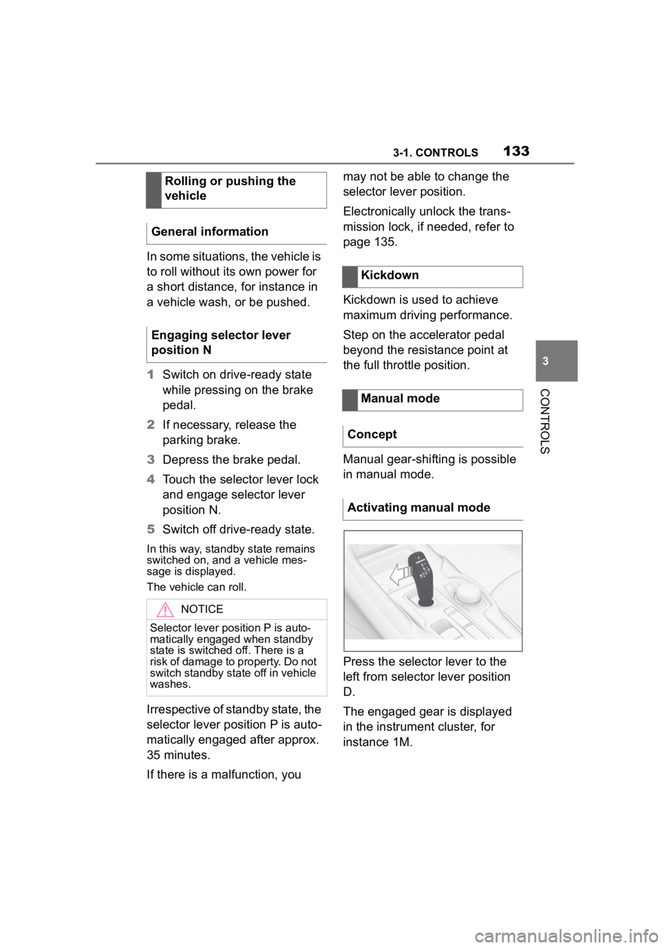
Press the selector lever to the
left from selector lever position
D.
The engaged gear is displayed
in the instrument cluster, for
instance 1M.
Rolling or pushing the
vehicle
General information
Engaging selector lever
position N
NOTICE
Selector lever position P is auto-
matically engaged when standby
state is switched off. There is a
risk of damage to property. Do not
switch standby state off in vehicle
washes.
Kickdown
Manual mode
Concept
Activating manual mode
Page 135 of 372

1353-1. CONTROLS
3
CONTROLSElectronically unlock the trans-
mission lock to maneuver vehi-
cle from a danger area.
Unlocking is possible, if the
starter can spin the engine.
Before unlocking the transmis-
sion lock, set the parking brake
to prevent the vehicle from roll-
ing away.
1Press and hold down brake
pedal.
2 Press the Start/Stop button.
The starter must audibly
start. Hold the Start/Stop but-
ton pressed.
3 With your free hand, press
the button on the selector
lever, arrow 1, and press the
selector lever into selector
lever position N and hold,
arrow N, until selector lever position N is displayed in the
instrument cluster.
A vehicle messag
e is displayed.
4Release Start/Stop button
and selector lever.
5 Release brake, as soon as
the starter stops.
6 Maneuver the vehicle from
the danger area and secure it
against moving on its own.
For additional information, see
the chapter on tow-starting and
towing, refer to page 326.
Launch Control enables opti-
mum acceleration on surfaces
with good traction under dry sur-
rounding conditions.
The use of Launch Control
causes premature component
wear since this function rep-
resents a very heavy load for
the vehicle.
Displays in the instrument
cluster
The selector lever posi-
tion is displayed, for
example P.
Electronic unlocking of
the transmission lock
General information
Engaging selector lever
position N
Launch Control
Concept
General information
1
R
N
Page 141 of 372

1413-1. CONTROLS
3
CONTROLS
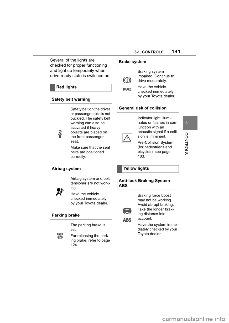
Several of the lights are
checked for proper functioning
and light up temporarily when
drive-ready state is switched on.Red lights
Safety belt warning
Safety belt on the driver
or passenger side is not
buckled. The safety belt
warning can also be
activated if heavy
objects are placed on
the front passenger
seat.
Make sure that the seat
belts are positioned
correctly.
Airbag system
Airbag system and belt
tensioner are not work-
ing.
Have the vehicle
checked immediately
by your Toyota dealer.
Parking brake
The parking brake is
set.
For releasing the park-
ing brake, refer to page
124.
Brake system
Braking system
impaired. Continue to
drive moderately.
Have the vehicle
checked immediately
by your Toyota dealer.
General risk of collision
Indicator light illumi-
nates or flashes in con-
junction with an
acoustic signal if a colli-
sion is imminent.
Pre-Collision System
(for pedestrians and
bicycles), see page
183.
Yellow lights
Anti-lock Braking System
ABS
Braking force boost
may not be working.
Avoid abrupt braking.
Take the longer brak-
ing distance into
account.
Have the system imme-
diately checked by your
Toyota dealer.
Page 165 of 372

1653-1. CONTROLS
3
CONTROLS
Airbags are not triggered in
every impact situation, for
instance in less severe acci-
dents.
Keep a distance from the air-
bags.
Always grasp the steering
wheel on the steering wheel
rim. Hold your hands at the 3
o'clock and 9 o'clock posi-
tions, to keep the risk of injury
to your hands or arms as low
as possible when the airbag is
triggered.
Adjust seat and steering
wheel so that hands can be
crossed over the steering
wheel. Select the settings so
that the shoulder rests against
the backrest when crossing
the hands and the upper body is as far back as possible
while still maintaining a com-
fortable grip on the steering
wheel.
Make sure that the front pas-
senger is sitting correctly, i.e.,
keeps his or her feet and legs
in the floor area and does not
support them on the dash-
board.
Make sure that occupants
keep their heads away from
the side airbag.
There should be no addi-
tional persons, animals or
objects between an airbag
and a person.
Dashboard and windshield on
the front passenger side must
stay clear - do not attach
adhesive labels or coverings
and do not attach brackets or
cables, for instance for GPS
devices or mobile phones.
Do not apply adhesive materi-
als to the airbag cover panels,
do not cover them or modify
them in any way.
Do not use the cover of the
front airbag on the front pas-
senger side as a storage
area.
Do not attach slip covers, seat
cushions or other objects to
the front passenger seat that
are not specifically suited for
seats with integrated side air-
bags.
Protective effect
General information
Information on optimum
effect of the airbags
WARNING
If the seat position is incorrect or
the deployment area of the air-
bags is impaired, the airbag sys-
tem cannot provide protection as
intended and ma y cause addi-
tional injuries due to triggering.
There is a risk o f injuries or dan-
ger to life. Follow the information
on achieving the optimum protec-
tive effect of the airbag system.
Page 194 of 372

1943-1. CONTROLS
Via Toyota Supra Command:
1"My Vehicle"
2 "Vehicle settings"
3 "Toyota Supra Safety"
4 "Blind spot monitor"
5 Select the desired setting.
"Off": with this setting, no warning is
output.
Via Toyota Supra Command:
1"My Vehicle"
2 "Vehicle settings"
3 "Steering wheel vibration"
4 Select the desired setting.
The dimmed light in the exterior
mirror indicates when there are
vehicles in the blind spot or approaching from behind.
If the turn signal is switched on
while a vehicle is in the critical
zone, the steering wheel
vibrates briefly and the light in
the exterior mirror flashes
brightly.
The warning stops when the
other vehicle has left the critical
area or after deactivation of the
turn signal.
A flashing of the light during
vehicle unlocking serves as sys-
tem self-test.
If the vehicle speed exceeds
approx. 155 mph/250 km/h, the
Setting the warning time
Setting the force of the steer-
ing wheel vibration
Warning function
Light in the exterior mirror
Prewarning
Acute warning
Flashing of the light
System limits
Safety information
WARNING
The system is designed to oper-
ate in certain conditions and cir-
cumstances. Due to conditions or
other factors, the system may not
respond. There may be a risk of
accident or risk of damage to
property. Actively intervene as
needed. Refer to the information
in this Owner’s Manual regarding
the scope of the system’s opera-
tion and limitations.
Upper speed limit