Page 262 of 372

2624-1. DRIVING TIPS
perforated brake discs can emit
functional noises. However,
functional noises have no effect
on the performance and opera-
tional reliability of the brake.
When roads are wet, salted, or
in heavy rain, gently press the
brake pedal every few miles.
Ensure that this action does not
endanger other traffic.
The heat generated during brak-
ing dries brake discs and brake
pads and protects them against
corrosion.
In this way braking efficiency will
be available when you need it.
■General information
Drive long or steep downhill gra-
dients in the gear that requires
least braking effort. Otherwise,
the brakes may overheat and
reduce brake efficiency.
You can increase the engine's
braking effect by shifting down,
going all the way to first gear, if
needed.
■Safety information
Corrosion on the brake discs
and contamination on the brake
pads are increased by the fol-
lowing circumstances:
Low mileage.
Extended periods when the
vehicle is not used at all.
Objects in the area around
the pedals
WARNING
Objects in the dri
ver's floor area
can limit the peda l distance or
block a depressed pedal. There is
a risk of an accident. Stow objects
in the vehicle such that they are
secured and cannot enter into the
driver's floor area. Use floor mats
that are suitable for the vehicle
and can be safely attached to the
floor. Do not use loose floor mats
and do not layer several floor
mats. Make sure that there is suf-
ficient clearance for the pedals.
Ensure that the floor mats are
securely fastened again after they
were removed, fo r instance for
cleaning.
Driving in wet conditions
Hills
WARNING
Light but consis tent brake pres-
sure can lead to high tempera-
tures, brakes wearing out and
possibly even brake failure. There
is a risk of an accident. Avoid
placing excessive stress on the
brake system.
WARNING
In idle state or with the engine
switched off, safety functions, for
instance engine braking effect,
braking assistance and steering
assistance, may not be available.
There is a risk of accident. Do not
attempt to drive in idle state or
with the engine switched off.
Brake disc corrosion
Page 269 of 372
2695-1. MOBILITY
5
MOBILITY
2Turn the fuel cap counter-
clockwise.
3 Place the fuel cap in the
bracket attached to the fuel
filler flap.
1 Fit the cap and turn it clock-
wise until you clearly hear a
click.
2 Press on the fuel filler flap
until it engages. It may be necessary in certain
situations to unlock the fuel filler
flap manually, e.g. with an elec-
trical fault.
Have fuel filler flap unlocked by
your Toyota dealer.
Closing
WARNING
The retaining strap of the fuel cap
can be jammed and crushed
during closing. The cap cannot be
correctly closed. Fuel or fuel
vapors can escape. There is a
risk of injury or risk of damage to
property. Pay attention that the
retaining strap is not jammed or
crushed when closing the cap.
Manually unlocking fuel
filler flap
Page 280 of 372

2805-1. MOBILITY
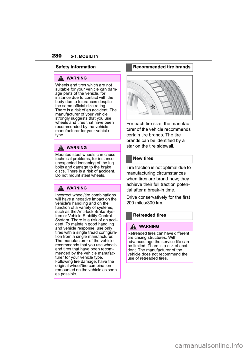
For each tire size, the manufac-
turer of the vehicle recommends
certain tire brands. The tire
brands can be identified by a
star on the tire sidewall.
Tire traction is not optimal due to
manufacturing circumstances
when tires are brand-new; they
achieve their full traction poten-
tial after a break-in time.
Drive conservatively for the first
200 miles/300 km.
Safety information
WARNING
Wheels and tires which are not
suitable for your
vehicle can dam-
age parts of the vehicle, for
instance due to contact with the
body due to tolerances despite
the same official size rating.
There is a risk of an accident. The
manufacturer of your vehicle
strongly suggests that you use
wheels and tires that have been
recommended by the vehicle
manufacturer for your vehicle
type.
WARNING
Mounted steel wheels can cause
technical problem s, for instance
unexpected loosening of the lug
bolts and damage to the brake
discs. There is a risk of accident.
Do not mount steel wheels.
WARNING
Incorrect wheel/tire combinations
will have a negative impact on the
vehicle's handling and on the
function of a variety of systems,
such as the Anti-lock Brake Sys-
tem or Vehicle S tability Control
System. There is a risk of an acci-
dent. To maintain good handling
and vehicle response, use only
tires with a single tread configura-
tion from a single manufacturer.
The manufacturer of the vehicle
recommends that you use wheels
and tires that have been recom-
mended by the vehicle manufac-
turer for your vehicle type.
Following tire damage, have the
original wheel/tire combination
remounted on the vehicle as soon
as possible.
Recommended tire brands
New tires
Retreaded tires
WARNING
Retreaded tires can have different
tire casing structures. With
advanced age the service life can
be limited. There is a risk of acci-
dent. The manufacturer of the
vehicle does not recommend the
use of retreaded tires.
Page 282 of 372

2825-1. MOBILITY
• Park the vehicle as far away as possible from passing traf-
fic and on solid ground.
• Switch on the hazard warning system.
• Secure the vehicle against rolling away by setting the
parking brake.
• Turn the steering wheel until the front wheels are in the
straight-ahead position and
engage the steering wheel
lock.
• Have all vehicle occupants get out of the vehicle and
ensure that they remain out-
side the immediate area in a
safe place, such as behind a
guardrail.
• If necessary, set up a warning triangle at an appropriate dis-
tance.
With the Mobility System, minor
tire damage can be sealed tem-
porarily to enable continued
travel. To accomplish this, seal-
ant is pumped into the tires,
which seals the damage from
the inside. • Follow the instructions on
using the Mobility System
found on the compressor and
sealant container.
• Use of the Mobility System may be ineffective if the tire
puncture measures approx.
1/8 inches/4 mm or more.
• Contact your Toyota dealer if the tire cannot be made driv-
able.
• Do not remove foreign bodies that have penetrated the tire.
Only remove foreign objects if
they are visibly protruding
from the tire.
• Pull the speed limit sticker off the sealant container and
apply it to the steering wheel.
• The use of a sealant can
damage the TPM wheel elec-
tronics. In this case, have the
electronics checked and
replaced at the next opportu-
nity.
• The compressor can be used to check the tire inflation pres-
sure.
Repairing a flat tire
Safety measures
Mobility System
Concept
General information
Page 283 of 372
2835-1. MOBILITY
5
MOBILITY
The Mobility System is located in
the right storage compartment of the
cargo area.
• Sealant container, arrow 1.
• Filling hose, arrow 2.
Observe use-by date on the
sealant container. 1
Sealant container unlocking
2 Sealant container holder
3 Tire pressure gauge
4 Reduce tire inflation pressure
button
5 On/off switch
6 Compressor
7 Connector/cable for socket
8 Connection hose
• Park the vehicle as far away as possible from passing traf-
fic and on solid ground.
• Switch on the hazard warning system.
• Secure the vehicle against rolling away by setting the
parking brake.
• Turn the steering wheel until the front wheels are in the
straight-ahead position and
engage the steering wheel
lock.
• Have all vehicle occupants get out of the vehicle and
ensure that they remain out-
side the immediate area in a
Overview
Storage
Sealant container
Compressor
Safety measures
Page 284 of 372

2845-1. MOBILITY
safe place, such as behind a
guardrail.
• If necessary, set up a warning triangle at an appropriate dis-
tance.
1 Shake the sealant container. 2
Pull filling hose completely
out of the cover of the sealant
container. Do not kink the
hose.
3 Slide the sealant container
into the holder on the com-
pressor housing, ensuring
that it engages audibly.
4 Screw the filling hose of the
sealant container onto the
tire valve of the nonworking
wheel.
5 With the compressor
switched off, insert the plug
Filling the tire with sealant
Safety information
WARNING
If the exhaust pipe is blocked or
ventilation is insufficient, harmful
exhaust gases can enter into the
vehicle. The exhaust gases con-
tain pollutants which are colorless
and odorless. In enclosed areas,
exhaust gases can also accumu-
late outside of the vehicle. There
is danger to life. Keep the exhaust
pipe free and ensure sufficient
ventilation.
NOTICE
The compressor can overheat
during extended operation. There
is a risk of damage to property. Do
not run the compressor for more
than 10 minutes.
Filling
Page 285 of 372

2855-1. MOBILITY
5
MOBILITY
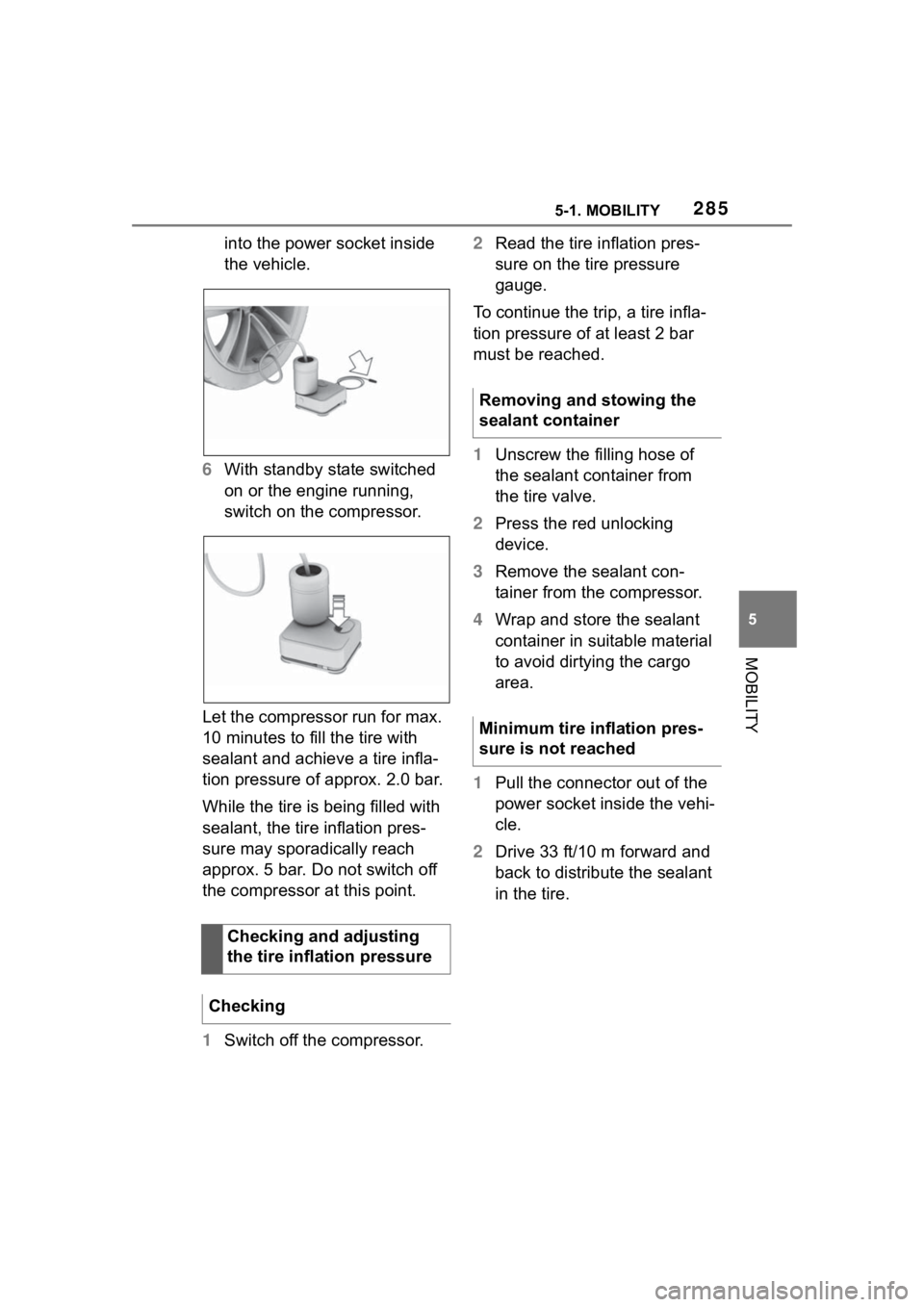
into the power socket inside
the vehicle.
6 With standby state switched
on or the engine running,
switch on the compressor.
Let the compressor run for max.
10 minutes to fill the tire with
sealant and achieve a tire infla-
tion pressure of approx. 2.0 bar.
While the tire is being filled with
sealant, the tire inflation pres-
sure may sporadically reach
approx. 5 bar. Do not switch off
the compressor at this point.
1 Switch off the compressor. 2
Read the tire inflation pres-
sure on the tire pressure
gauge.
To continue the trip, a tire infla-
tion pressure of at least 2 bar
must be reached.
1 Unscrew the filling hose of
the sealant container from
the tire valve.
2 Press the red unlocking
device.
3 Remove the sealant con-
tainer from the compressor.
4 Wrap and store the sealant
container in suitable material
to avoid dirtying the cargo
area.
1 Pull the connector out of the
power socket inside the vehi-
cle.
2 Drive 33 ft/10 m forward and
back to distribute the sealant
in the tire.
Checking and adjusting
the tire inflation pressure
Checking
Removing and stowing the
sealant container
Minimum tire inflation pres-
sure is not reached
Page 296 of 372

2965-1. MOBILITY
tioning properly. Always
check the TPMS malfunction
telltale after replacing one or
more tires or wheels on your
vehicle to ensure that the
replacement or alternate tires
and wheels allow the TPMS
to continue to function prop-
erly.
If a tire is punctured and loses
pressure, it is not necessary to
replace the tire immediately if a
tire repair kit (Mobility System) is
used.
If needed, the tools for changing
wheels are available as acces-
sories from your Toyota dealer.
*: if equipped
The wheel lug bolts have a spe-
cial coding. The lug bolts can
only be released with the
adapter which matches the cod- ing.
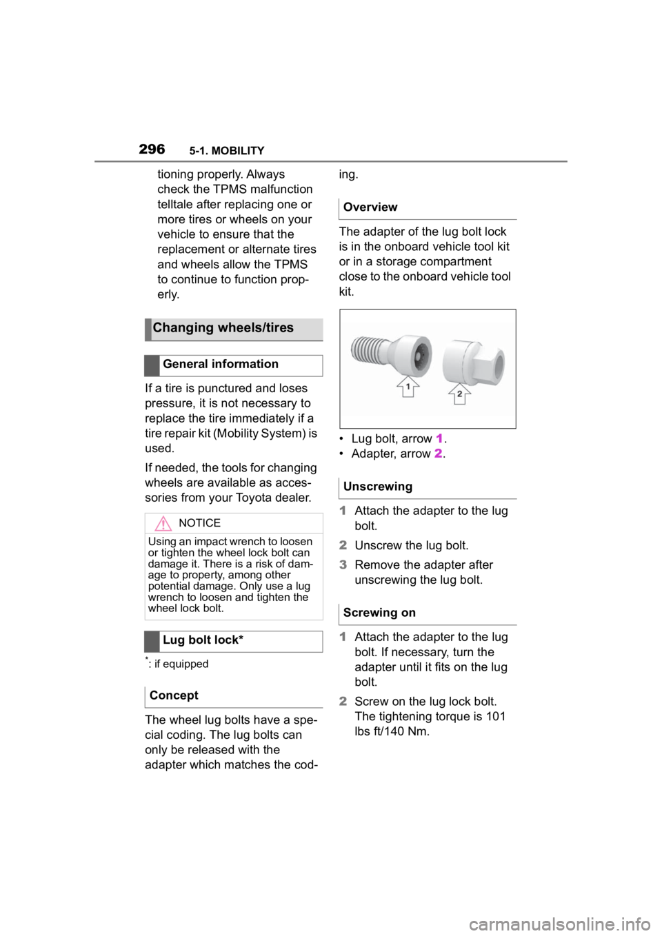
The adapter of the lug bolt lock
is in the onboard vehicle tool kit
or in a storage compartment
close to the onboard vehicle tool
kit.
• Lug bolt, arrow
1.
• Adapter, arrow 2.
1 Attach the adapter to the lug
bolt.
2 Unscrew the lug bolt.
3 Remove the adapter after
unscrewing the lug bolt.
1 Attach the adapter to the lug
bolt. If necessary, turn the
adapter until it fits on the lug
bolt.
2 Screw on the lug lock bolt.
The tightening torque is 101
lbs ft/140 Nm.
Changing wheels/tires
General information
NOTICE
Using an impact wrench to loosen
or tighten the wheel lock bolt can
damage it. There is a risk of dam-
age to property, among other
potential damage. Only use a lug
wrench to loosen and tighten the
wheel lock bolt.
Lug bolt lock*
Concept
Overview
Unscrewing
Screwing on