Page 254 of 372

2543-1. CONTROLS
3Subtract the combined
weight of the driver and pas-
sengers from XXX kg or XXX
lbs.
4 The resulting figure equals
the available amount of cargo
and luggage load capacity.
For example, if the “XXX”
amount equals 1,400 lbs and
there will be five 150 lbs pas-
sengers in your vehicle, the
amount of available cargo
and luggage load capacity is
650 lbs (1,400–750 (5 x 150)
= 650 lbs).
5 Determine the combined
weight of luggage and cargo
being loaded on the vehicle.
That weight may not safely
exceed the available cargo
and luggage load capacity
calculated in Step 4.
6 If your vehicle will be towing
a trailer, load from your trailer
will be transferred to your
vehicle. Consult this manual
to determine how this
reduces the available cargo
and luggage load capacity of
your vehicle. The maximum load is the sum of
the weight of the occupants and
the cargo.
The greater the weight of the
occupants, the less cargo that
can be transported.
Cover sharp edges and cor-
ners on the cargo.
Heavy cargo: stow as far for-
ward and as low as possible,
ideally directly behind the
cargo partition.
Smaller and lighter cargo:
secure with ratchet straps or
with a cargo net or draw
straps.
Larger and heavy cargo:
secure with cargo straps.
*: if equipped
Load
Stowing and securing
cargo
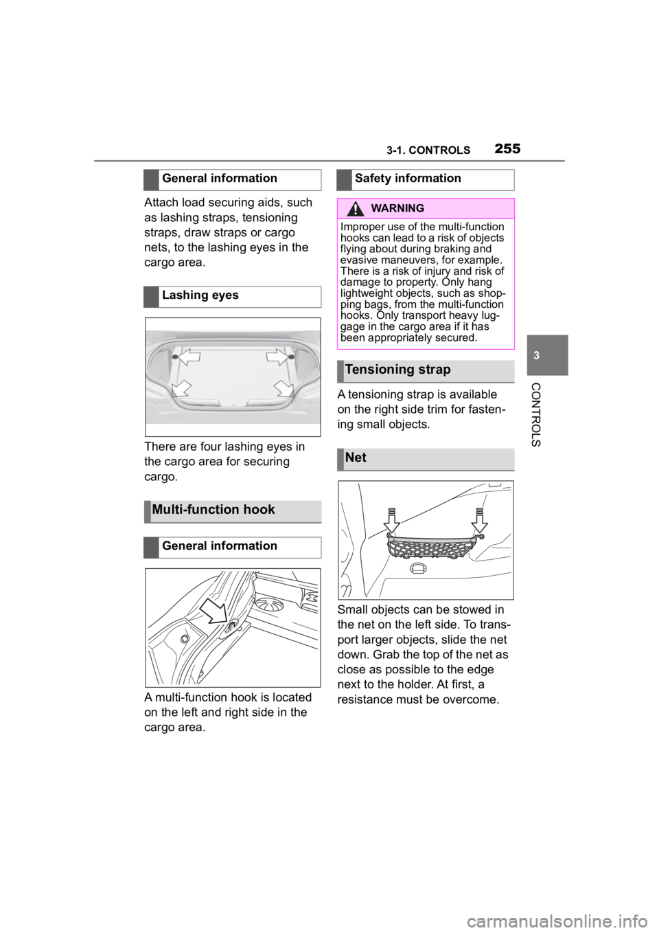
Lashing eyes in the cargo
area*
Page 255 of 372

2553-1. CONTROLS
3
CONTROLS
Attach load securing aids, such
as lashing straps, tensioning
straps, draw straps or cargo
nets, to the lashing eyes in the
cargo area.
There are four lashing eyes in
the cargo area for securing
cargo.
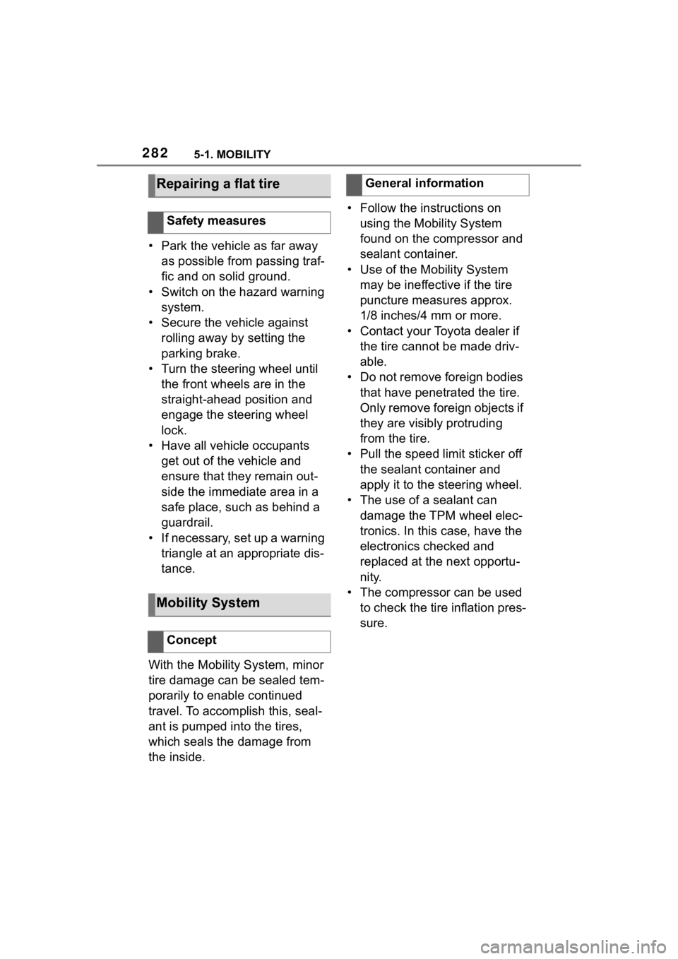
A multi-function hook is located
on the left and right side in the
cargo area.A tensioning strap is available
on the right side trim for fasten-
ing small objects.
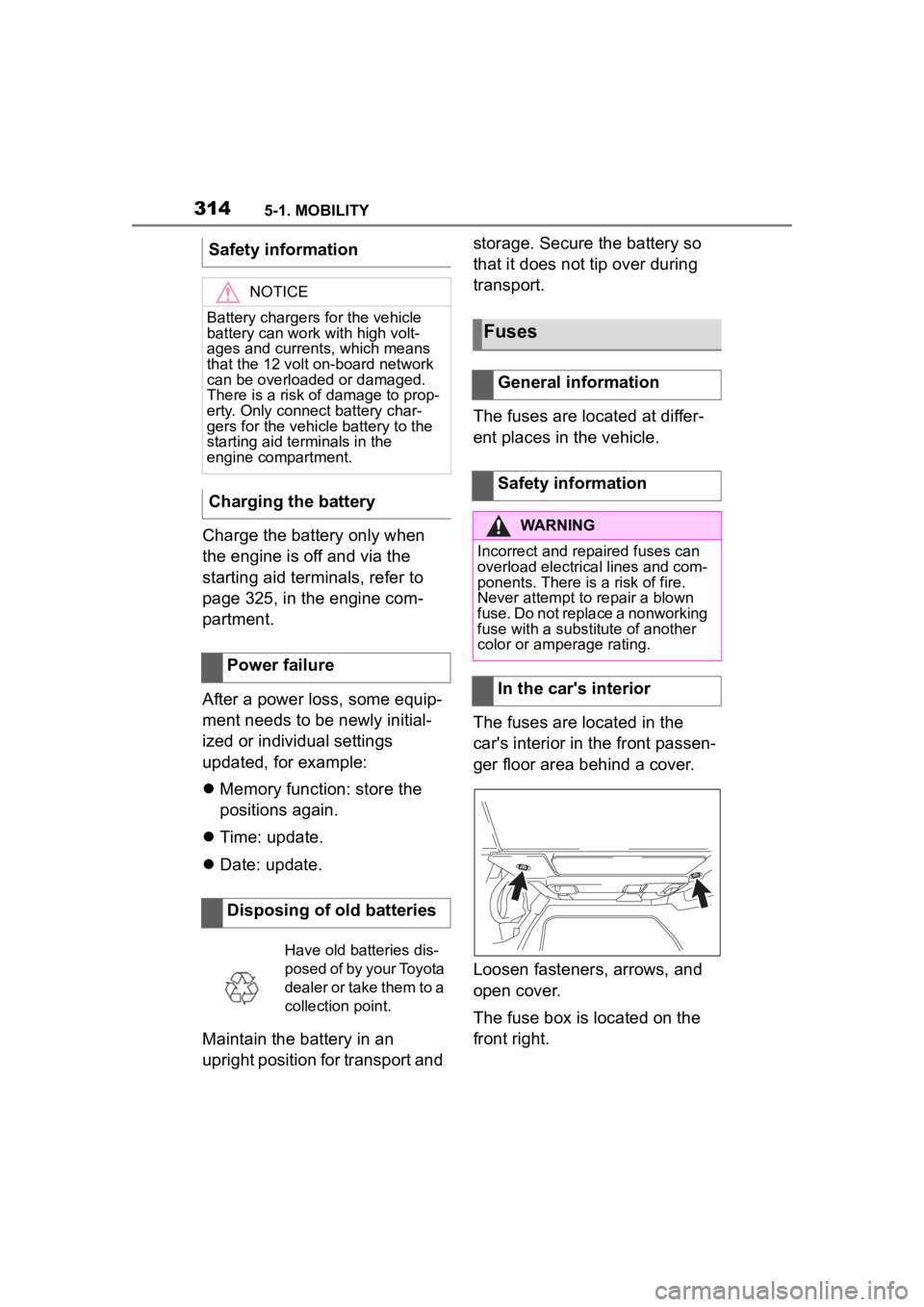
Small objects can be stowed in
the net on the left side. To trans-
port larger objects, slide the net
down. Grab the top of the net as
close as possible to the edge
next to the holder. At first, a
resistance must be overcome.
General information
Lashing eyes
Multi-function hook
General information
Safety information
WARNING
Improper use of the multi-function
hooks can lead to a risk of objects
flying about during braking and
evasive maneuvers, for example.
There is a risk of injury and risk of
damage to property. Only hang
lightweight objects, such as shop-
ping bags, from the multi-function
hooks. Only transport heavy lug-
gage in the cargo
area if it has
been appropriately secured.
Tensioning strap
Net
Page 262 of 372

2624-1. DRIVING TIPS
perforated brake discs can emit
functional noises. However,
functional noises have no effect
on the performance and opera-
tional reliability of the brake.
When roads are wet, salted, or
in heavy rain, gently press the
brake pedal every few miles.
Ensure that this action does not
endanger other traffic.
The heat generated during brak-
ing dries brake discs and brake
pads and protects them against
corrosion.
In this way braking efficiency will
be available when you need it.
■General information
Drive long or steep downhill gra-
dients in the gear that requires
least braking effort. Otherwise,
the brakes may overheat and
reduce brake efficiency.
You can increase the engine's
braking effect by shifting down,
going all the way to first gear, if
needed.
■Safety information
Corrosion on the brake discs
and contamination on the brake
pads are increased by the fol-
lowing circumstances:
Low mileage.
Extended periods when the
vehicle is not used at all.
Objects in the area around
the pedals
WARNING
Objects in the dri
ver's floor area
can limit the peda l distance or
block a depressed pedal. There is
a risk of an accident. Stow objects
in the vehicle such that they are
secured and cannot enter into the
driver's floor area. Use floor mats
that are suitable for the vehicle
and can be safely attached to the
floor. Do not use loose floor mats
and do not layer several floor
mats. Make sure that there is suf-
ficient clearance for the pedals.
Ensure that the floor mats are
securely fastened again after they
were removed, fo r instance for
cleaning.
Driving in wet conditions
Hills
WARNING
Light but consis tent brake pres-
sure can lead to high tempera-
tures, brakes wearing out and
possibly even brake failure. There
is a risk of an accident. Avoid
placing excessive stress on the
brake system.
WARNING
In idle state or with the engine
switched off, safety functions, for
instance engine braking effect,
braking assistance and steering
assistance, may not be available.
There is a risk of accident. Do not
attempt to drive in idle state or
with the engine switched off.
Brake disc corrosion
Page 282 of 372

2825-1. MOBILITY
• Park the vehicle as far away as possible from passing traf-
fic and on solid ground.
• Switch on the hazard warning system.
• Secure the vehicle against rolling away by setting the
parking brake.
• Turn the steering wheel until the front wheels are in the
straight-ahead position and
engage the steering wheel
lock.
• Have all vehicle occupants get out of the vehicle and
ensure that they remain out-
side the immediate area in a
safe place, such as behind a
guardrail.
• If necessary, set up a warning triangle at an appropriate dis-
tance.
With the Mobility System, minor
tire damage can be sealed tem-
porarily to enable continued
travel. To accomplish this, seal-
ant is pumped into the tires,
which seals the damage from
the inside. • Follow the instructions on
using the Mobility System
found on the compressor and
sealant container.
• Use of the Mobility System may be ineffective if the tire
puncture measures approx.
1/8 inches/4 mm or more.
• Contact your Toyota dealer if the tire cannot be made driv-
able.
• Do not remove foreign bodies that have penetrated the tire.
Only remove foreign objects if
they are visibly protruding
from the tire.
• Pull the speed limit sticker off the sealant container and
apply it to the steering wheel.
• The use of a sealant can
damage the TPM wheel elec-
tronics. In this case, have the
electronics checked and
replaced at the next opportu-
nity.
• The compressor can be used to check the tire inflation pres-
sure.
Repairing a flat tire
Safety measures
Mobility System
Concept
General information
Page 283 of 372
2835-1. MOBILITY
5
MOBILITY
The Mobility System is located in
the right storage compartment of the
cargo area.
• Sealant container, arrow 1.
• Filling hose, arrow 2.
Observe use-by date on the
sealant container. 1
Sealant container unlocking
2 Sealant container holder
3 Tire pressure gauge
4 Reduce tire inflation pressure
button
5 On/off switch
6 Compressor
7 Connector/cable for socket
8 Connection hose
• Park the vehicle as far away as possible from passing traf-
fic and on solid ground.
• Switch on the hazard warning system.
• Secure the vehicle against rolling away by setting the
parking brake.
• Turn the steering wheel until the front wheels are in the
straight-ahead position and
engage the steering wheel
lock.
• Have all vehicle occupants get out of the vehicle and
ensure that they remain out-
side the immediate area in a
Overview
Storage
Sealant container
Compressor
Safety measures
Page 298 of 372
2985-1. MOBILITY
1Filler neck for washer fluid
2 Jump-starting, negative battery terminal
3 Jump-starting, positive battery terminal
4 Oil filler neck
5 Coolant reservoir, auxiliary cooling
6 Coolant reservoir, engine
7 Vehicle identification number
Overview
Hood
Safety information
WARNING
Improperly executed work in the
engine compartment can damage
vehicle components and impair
vehicle functions. There is a risk
of an accident and damage to
property. Have work in the engine
compartment performed by your
Toyota dealer.
WARNING
The engine compartment accom-
modates moving components.
Certain components in the engine
compartment can also move with
the vehicle switched off, for
instance the radiator fan. There is
a risk of injury. Do not reach into
the area of moving parts. Keep
articles of clothing and hair away
from moving parts.
Page 314 of 372

3145-1. MOBILITY
Charge the battery only when
the engine is off and via the
starting aid terminals, refer to
page 325, in the engine com-
partment.
After a power loss, some equip-
ment needs to be newly initial-
ized or individual settings
updated, for example:
Memory function: store the
positions again.
Time: update.
Date: update.
Maintain the battery in an
upright position for transport and storage. Secure the battery so
that it does not tip over during
transport.
The fuses are located at differ-
ent places in the vehicle.
The fuses are located in the
car's interior in the front passen-
ger floor area behind a cover.
Loosen fasteners, arrows, and
open cover.
The fuse box is located on the
front right.
Safety information
NOTICE
Battery chargers for the vehicle
battery can work with high volt-
ages and currents, which means
that the 12 volt on-board network
can be overloaded or damaged.
There is a risk of damage to prop-
erty. Only connect battery char-
gers for the vehi
cle battery to the
starting aid terminals in the
engine compartment.
Charging the battery
Power failure
Disposing of old batteries
Have old batteries dis-
posed of by your Toyota
dealer or take them to a
collection point.
Fuses
General information
Safety information
WARNING
Incorrect and repaired fuses can
overload electrical lines and com-
ponents. There is a risk of fire.
Never attempt to repair a blown
fuse. Do not replace a nonworking
fuse with a substitute of another
color or amperage rating.
In the car's interior
Page 319 of 372

3195-1. MOBILITY
5
MOBILITY
Seat heating
Seat setting
Crash-security module
Switching center column,
Light switch element,
steering Operating panel
Audio
HiFi amplifier, Video mod-
ule TV
Rear-view mirror
Overhead function cen-
ter, Exterior door handle
electronics
Instrument cluster
Additional battery: Dual
Accumulator System
(DSS)
Fuel pump control elec-
tronics, Natural Vacuum
Leak Detection, Gas gen-
erator for battery safety
terminal, Remote control
receiver
Electric window opener
Heating and air-condi-
tioning system
Vehicle's diagnostic port
(interface)
SymbolMeaning
Interior lights in the boot
Vertical Dynamic platform
Vertical Dynamic platform
Vertical Dynamic platform
Mono Camera (Kafas)
Head Unit
Active Sound Design
USB Hub
Body Domain Controller
Controller (Toyota Supra
Command)
Electric fan (air cooler),
Controlled differential
lock
12 V socket, Cigarette
lighter
Interior lights in the boot
Door lock, Exterior door
handle electronics,
Telematic Communica-
tion Box
Electronic gear box con-
trol
SymbolMeaning