2023 TOYOTA RAV4 HYBRID wheel torque
[x] Cancel search: wheel torquePage 121 of 586

1212-1. Instrument cluster
2
Vehicle status information and indicators
tance driven since hybrid sys-
tem start
*
• “Total Time”: Displays elapsed time since hybrid sys-
tem start
*
*: These items are reset each time the hybrid system stops.
■Trip information
2 items that are selected using
the “TRIP A Items” or “TRIP B
Items” setting (average speed
and distance) can be displayed
vertically.
Use the displayed information as a
reference only.
• “Average Speed”: Displays the average vehicle speed
since the display was reset
*
• “Distance”: Displays the dis-tance driven since the display
was reset
*
• “Total Time”: Displays the elapsed time since the display
was reset
*
*: To reset, display the desired item
and press and hold .
P.125 Torque distribution display
Displays the drive status of each
wheel in 6 steps from 0 to 5.
The illustration used is intended
as an example, and may differ
from the image that is actually
displayed on the multi-informa-
tion display.
Vehicle settings and the content
displayed on the screen can be
changed by using the meter
control switches.
■Setting procedure
1 Press and hold of the
meter control switches to dis-
play the cursor.
2 Press or with the cur-
sor on the content display
area (center) to select
and then press .
3 Press or of the meter
control switches and move
Energy monitor
AWD system display
Settings display
A
Page 328 of 586

3264-5. Using the driving support systems
■ECB (Electronically Con-
trolled Brake System)
The electronically controlled
system generates braking force
corresponding to the brake
operation
■ABS (Anti-lock Brake Sys-
tem)
Helps to prevent wheel lock
when the brakes are applied
suddenly, or if the brakes are
applied while driving on a slip-
pery road surface
■Brake assist
Generates an increased level of
braking force after the brake
pedal is depressed when the
system detects a panic stop sit-
uation
■VSC (Vehicle Stability Con-
trol)
Helps the driver to control skid-
ding when swerving suddenly or
turning on slippery road sur-
faces.
■Enhanced VSC (Enhanced
Vehicle Stability Control)
Provides cooperative control of
the ABS, TRAC, VSC and EPS.
Helps to maintain directional
stability when swerving on slip-
pery road surfaces by con-
trolling steering performance.
■Trailer Sway Control
Helps the driver to control trailer
sway by selectively applying
brake pressure for individual
wheels and reducing driving
torque when trailer sway is
detected.
■TRAC (Traction Control)
Helps to maintain drive power
and prevent the drive wheels
from spinning when starting the
vehicle or accelerating on slip-
pery roads
■Active Cornering Assist
(ACA)
Helps to prevent the vehicle
from drifting to the outer side by
performing inner wheel brake
control when attempting to
accelerate while turning
■Hill-start assist control
Helps to reduce the backward
Driving assist systems
To keep driving safety and
performance, the following
systems operate automati-
cally in response to various
driving situations. Be
aware, however, that these
systems are supplementary
and should not be relied
upon too heavily when oper-
ating the vehicle.
Summary of the driving
assist systems
Page 478 of 586
4767-2. Steps to take in an emergency
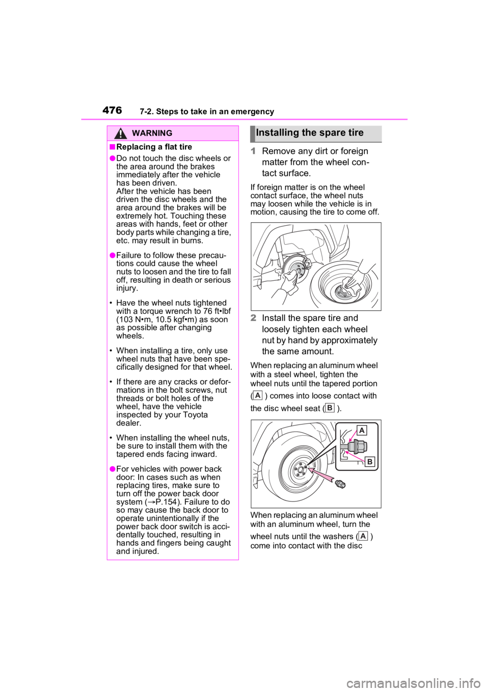
1Remove any dirt or foreign
matter from the wheel con-
tact surface.
If foreign matter is on the wheel
contact surface, the wheel nuts
may loosen while the vehicle is in
motion, causing the tire to come off.
2 Install the spare tire and
loosely tighten each wheel
nut by hand by approximately
the same amount.
When replacing an aluminum wheel
with a steel whee l, tighten the
wheel nuts until the tapered portion
( ) comes into loose contact with
the disc wheel seat ( ).
When replacing an aluminum wheel
with an aluminum wheel, turn the
wheel nuts until the washers ( )
come into contact with the disc
WARNING
■Replacing a flat tire
●Do not touch the disc wheels or
the area around the brakes
immediately after the vehicle
has been driven.
After the vehicle has been
driven the disc wheels and the
area around the brakes will be
extremely hot. Touching these
areas with hands , feet or other
body parts while changing a tire,
etc. may result in burns.
●Failure to follow these precau-
tions could cause the wheel
nuts to loosen and the tire to fall
off, resulting in death or serious
injury.
• Have the wheel nuts tightened with a torque wrench to 76 ft•lbf
(103 N•m, 10.5 kgf•m) as soon
as possible after changing
wheels.
• When installing a tire, only use wheel nuts that have been spe-
cifically designed for that wheel.
• If there are any cracks or defor- mations in the bolt screws, nut
threads or bolt holes of the
wheel, have the vehicle
inspected by your Toyota
dealer.
• When installing the wheel nuts,
be sure to install them with the
tapered ends facing inward.
●For vehicles with power back
door: In cases such as when
replacing tires, make sure to
turn off the power back door
system ( P.154). Failure to do
so may cause the back door to
operate unintentionally if the
power back door switch is acci-
dentally touched, resulting in
hands and fingers being caught
and injured.
Installing the spare tire
A
B
A
Page 479 of 586
4777-2. Steps to take in an emergency
7
When trouble arises
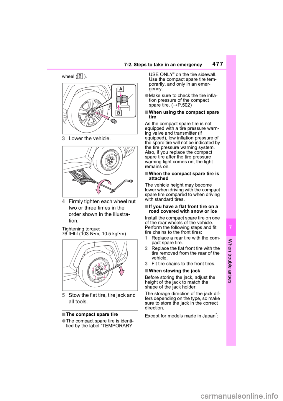
wheel ( ).
3Lower the vehicle.
4 Firmly tighten each wheel nut
two or three times in the
order shown in the illustra-
tion.
Tightening torque:
76 ft•lbf (103 N•m, 10.5 kgf•m)
5Stow the flat tire, tire jack and
all tools.
■The compact spare tire
●The compact spare tire is identi-
fied by the label “TEMPORARY USE ONLY” on the tire sidewall.
Use the compact spare tire tem-
porarily, and only in an emer-
gency.
●Make sure to check the tire infla-
tion pressure of the compact
spare tire. (
P.502)
■When using the compact spare
tire
As the compact spare tire is not
equipped with a tire pressure warn-
ing valve and transmitter (if
equipped), low inflation pressure of
the spare tire will not be indicated by
the tire pressure warning system.
Also, if you replace the compact
spare tire after the tire pressure
warning light com es on, the light
remains on.
■When the compact spare tire is
attached
The vehicle height may become
lower when driving with the compact
spare tire compared to when driving
with standard tires.
■If you have a flat front tire on a
road covered with snow or ice
Install the compact spare tire on one
of the rear wheels of the vehicle.
Perform the following steps and fit
tire chains to the front tires:
1 Replace a rear tire with the com-
pact spare tire.
2 Replace the flat front tire with the
tire removed from the rear of the
vehicle.
3 Fit tire chains to the front tires.
■When stowing the jack
Before storing the jack, adjust the
height of the ja ck to match the
shape of the jack holder.
The storage direction of the jack dif-
fers depending on the type, so make
sure to store the ja ck in the correct
direction.
Except for models made in Japan
*:
B
Page 504 of 586
5028-1. Specifications
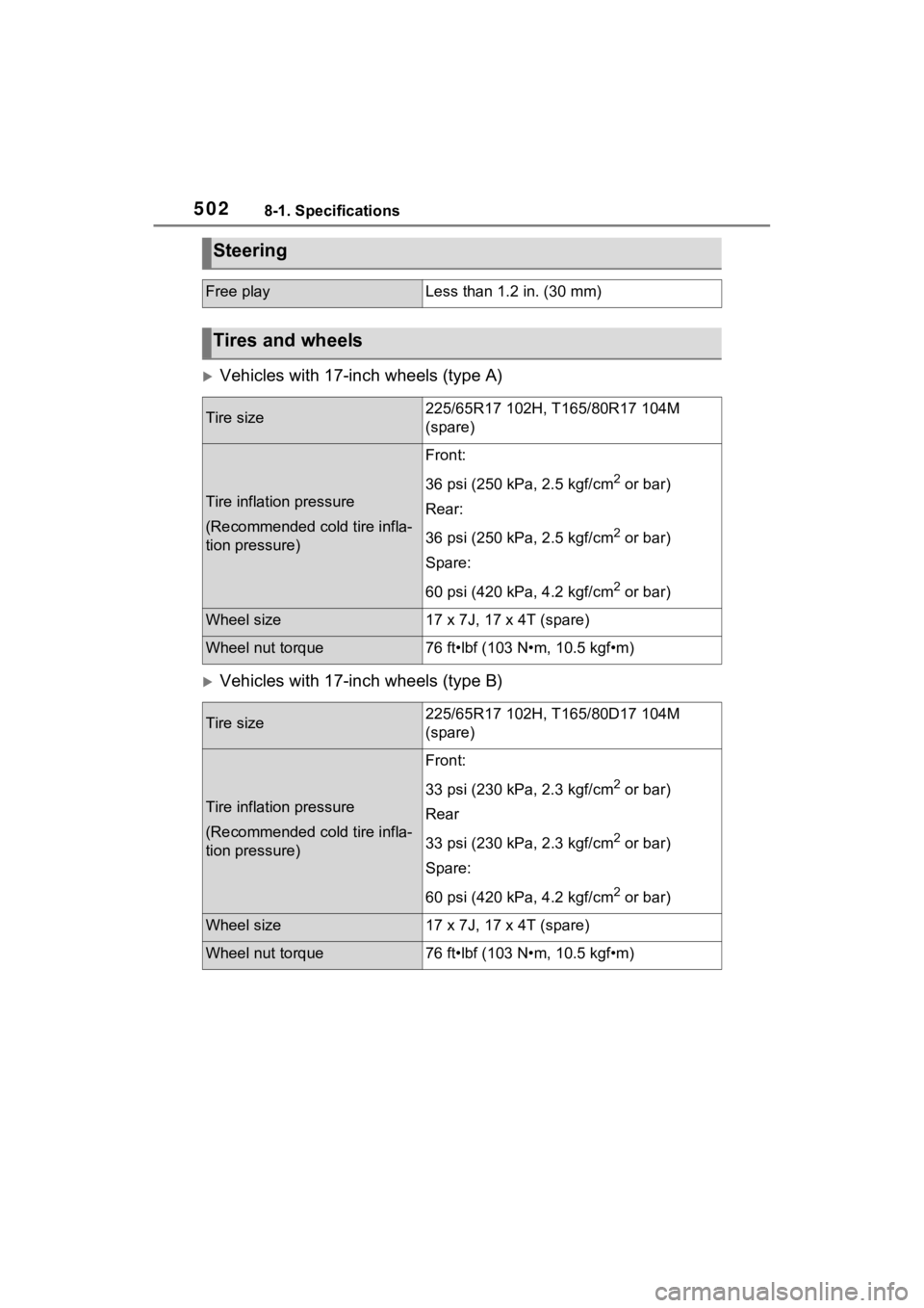
Vehicles with 17-inch wheels (type A)
Vehicles with 17-inch wheels (type B)
Steering
Free playLess than 1.2 in. (30 mm)
Tires and wheels
Tire size225/65R17 102H, T165/80R17 104M
(spare)
Tire inflation pressure
(Recommended cold tire infla-
tion pressure)
Front:
36 psi (250 kPa, 2.5 kgf/cm
2 or bar)
Rear:
36 psi (250 kPa, 2.5 kgf/cm
2 or bar)
Spare:
60 psi (420 kPa, 4.2 kgf/cm
2 or bar)
Wheel size17 x 7J, 17 x 4T (spare)
Wheel nut torque76 ft•lbf (103 N•m, 10.5 kgf•m)
Tire size225/65R17 102H, T165/80D17 104M
(spare)
Tire inflation pressure
(Recommended cold tire infla-
tion pressure)
Front:
33 psi (230 kPa, 2.3 kgf/cm
2 or bar)
Rear
33 psi (230 kPa, 2.3 kgf/cm
2 or bar)
Spare:
60 psi (420 kPa, 4.2 kgf/cm
2 or bar)
Wheel size17 x 7J, 17 x 4T (spare)
Wheel nut torque76 ft•lbf (103 N•m, 10.5 kgf•m)
Page 505 of 586
5038-1. Specifications
8
Vehicle specifications
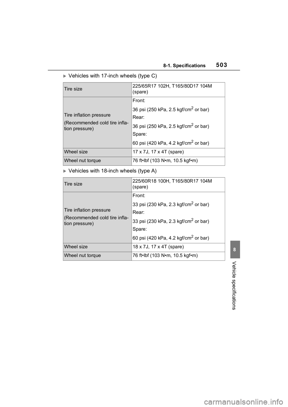
Vehicles with 17-inch wheels (type C)
Vehicles with 18-inch wheels (type A)
Tire size225/65R17 102H, T165/80D17 104M
(spare)
Tire inflation pressure
(Recommended cold tire infla-
tion pressure)
Front:
36 psi (250 kPa, 2.5 kgf/cm
2 or bar)
Rear:
36 psi (250 kPa, 2.5 kgf/cm
2 or bar)
Spare:
60 psi (420 kPa, 4.2 kgf/cm
2 or bar)
Wheel size17 x 7J, 17 x 4T (spare)
Wheel nut torque76 ft•lbf (103 N•m, 10.5 kgf•m)
Tire size225/60R18 100H, T165/80R17 104M
(spare)
Tire inflation pressure
(Recommended cold tire infla-
tion pressure)
Front:
33 psi (230 kPa, 2.3 kgf/cm
2 or bar)
Rear:
33 psi (230 kPa, 2.3 kgf/cm
2 or bar)
Spare:
60 psi (420 kPa, 4.2 kgf/cm
2 or bar)
Wheel size18 x 7J, 17 x 4T (spare)
Wheel nut torque76 ft•lbf (103 N•m, 10.5 kgf•m)
Page 506 of 586
5048-1. Specifications
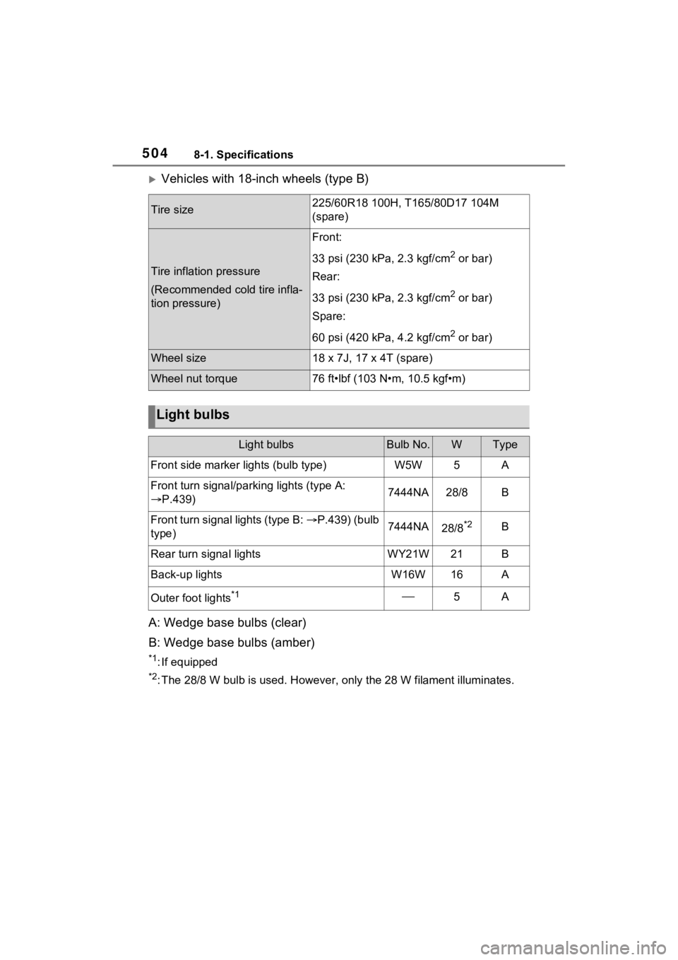
Vehicles with 18-inch wheels (type B)
A: Wedge base bulbs (clear)
B: Wedge base bulbs (amber)
*1: If equipped
*2: The 28/8 W bulb is used. Howev er, only the 28 W filament illuminates.
Tire size225/60R18 100H, T165/80D17 104M
(spare)
Tire inflation pressure
(Recommended cold tire infla-
tion pressure)
Front:
33 psi (230 kPa, 2.3 kgf/cm
2 or bar)
Rear:
33 psi (230 kPa, 2.3 kgf/cm
2 or bar)
Spare:
60 psi (420 kPa, 4.2 kgf/cm
2 or bar)
Wheel size18 x 7J, 17 x 4T (spare)
Wheel nut torque76 ft•lbf (103 N•m, 10.5 kgf•m)
Light bulbs
Light bulbsBulb No.WType
Front side marker lights (bulb type)W5W5A
Front turn signal/parking lights (type A:
P.439)7444NA28/8B
Front turn signal lights (type B: P.439) (bulb
type)7444NA28/8*2B
Rear turn signal lightsWY21W21B
Back-up lightsW16W16A
Outer foot lights*15A