Page 296 of 586

2944-5. Using the driving support systems
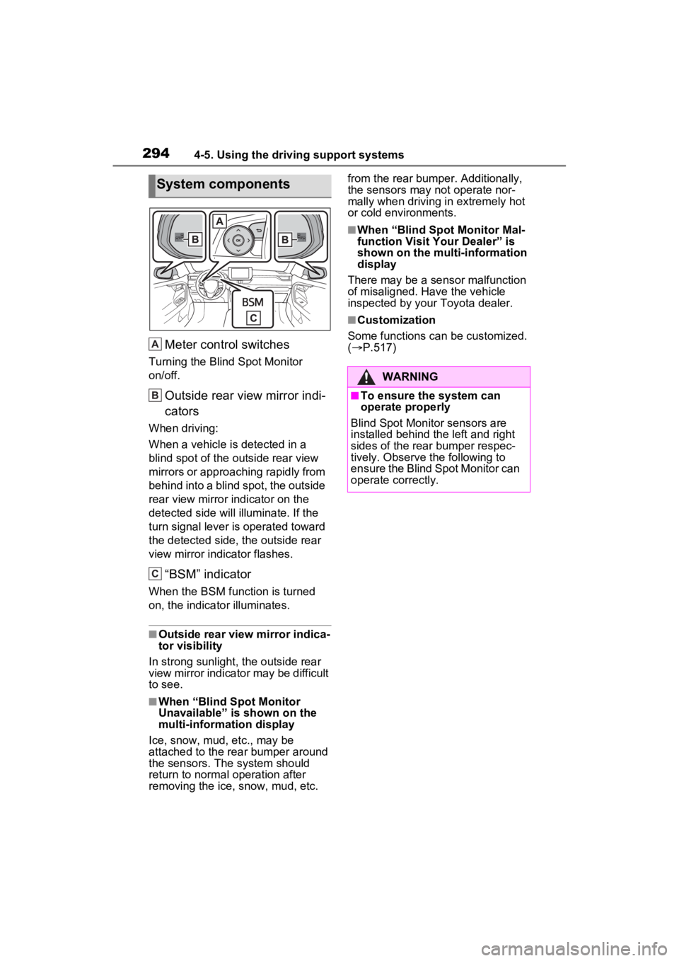
Meter control switches
Turning the Blind Spot Monitor
on/off.
Outside rear view mirror indi-
cators
When driving:
When a vehicle is detected in a
blind spot of the outside rear view
mirrors or approaching rapidly from
behind into a blind spot, the outside
rear view mirror indicator on the
detected side will illuminate. If the
turn signal lever is operated toward
the detected side, the outside rear
view mirror indicator flashes.
“BSM” indicator
When the BSM function is turned
on, the indicator illuminates.
■Outside rear view mirror indica-
tor visibility
In strong sunlight, the outside rear
view mirror indicato r may be difficult
to see.
■When “Blind Spot Monitor
Unavailable” is shown on the
multi-information display
Ice, snow, mud, etc., may be
attached to the rear bumper around
the sensors. The system should
return to normal operation after
removing the ice, snow, mud, etc. from the rear bumper. Additionally,
the sensors may not operate nor-
mally when driving in extremely hot
or cold environments.
■When “Blind Spot Monitor Mal-
function Visit Your Dealer” is
shown on the multi-information
display
There may be a sensor malfunction
of misaligned. Have the vehicle
inspected by your Toyota dealer.
■Customization
Some functions can be customized.
( P.517)
System components
A
B
C
�:�$�5�1�,�1�*
■To ensure the system can
operate properly
Blind Spot Monitor sensors are
installed behind the left and right
sides of the rear bumper respec-
tively. Observe the following to
ensure the Blind Spot Monitor can
operate correctly.
Page 382 of 586

3805-4. Using the other interior features
1Press and hold the desired
HomeLink
® button.
2 When the HomeLink
® indica-
tor starts flashing orange,
release the HomeLink
® but-
ton and perform “Program-
ming HomeLink
®” 1 (it takes
20 seconds for the
HomeLink
® indicator to start
flashing).
■Before programming
●Install a new battery in the trans-
mitter.
●The battery side of the transmitter
must be pointed away from the
HomeLink
® buttons.
Press the appropriate
HomeLink® button. The
HomeLink® indicator light
should turn on.
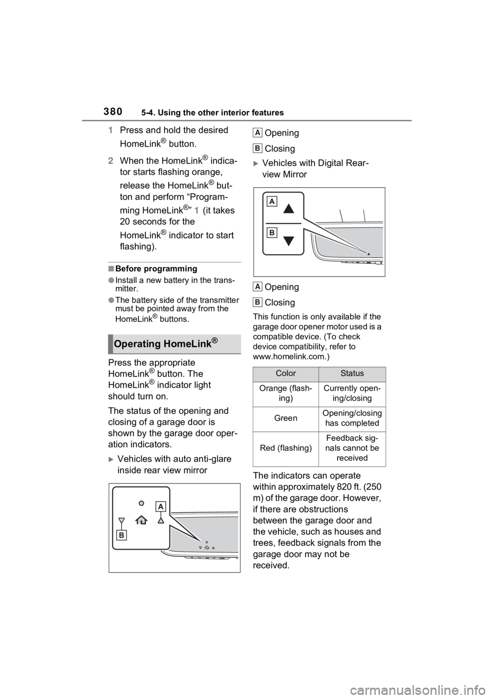
The status of the opening and
closing of a garage door is
shown by the garage door oper-
ation indicators.
Vehicles with auto anti-glare
inside rear view mirror Opening
Closing
Vehicles with Digital Rear-
view Mirror
Opening
Closing
This function is only available if the
garage door opener motor used is a
compatible device. (To check
device compatibility, refer to
www.homelink.com.)
The indicators can operate
within approximately 820 ft. (250
m) of the garage door. However,
if there are obstructions
between the garage door and
the vehicle, such as houses and
trees, feedback signals from the
garage door may not be
received.
Operating HomeLink®
ColorStatus
Orange (flash- ing)Currently open-ing/closing
GreenOpening/closing has completed
Red (flashing)
Feedback sig-
nals cannot be received
A
B
A
B
Page 441 of 586
4396-3. Do-it-yourself maintenance
6
Maintenance and care
1Using a Phillips-head screw-
driver, turn bolt A in either
direction.
Remember the turning direc-
tion and the number of turns.
2 Turn bolt B the same number
of turns and in the same
direction as step 1.
If the headlight cannot be adjusted
using this procedure, take the vehi-
cle to your Toyota dealer to adjust
the headlight aim.
Check the wattage of the light
bulb to be replaced. ( P.504)
Front (type A)
Front turn signal/parking
lights
Front side marker lights
Adjusting the headlight
aimLight bulbs
You may replace the follow-
ing bulbs by yourself. The
difficulty level of replace-
ment varies depending on
the bulb. If necessary bulb
replacement seems difficult
to perform, contact your
Toyota dealer.
For more information about
replacing other light bulbs,
contact your Toyota dealer.
Preparing for light bulb
replacement
Bulb location
A
B
Page 442 of 586

4406-3. Do-it-yourself maintenance
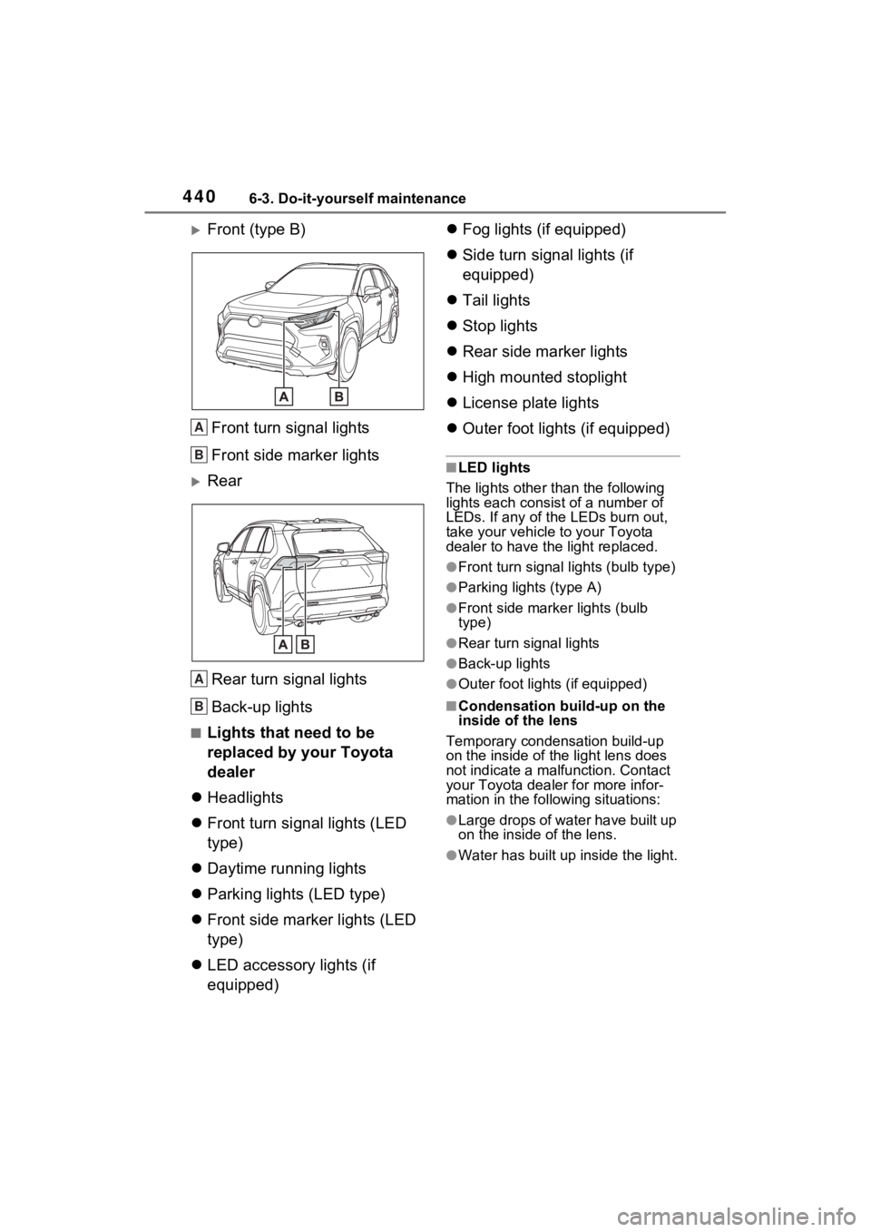
Front (type B)
Front turn signal lights
Front side marker lights
RearRear turn signal lights
Back-up lights
■Lights that need to be
replaced by your Toyota
dealer
Headlights
Front turn signal lights (LED
type)
Daytime running lights
Parking lights (LED type)
Front side marker lights (LED
type)
LED accessory lights (if
equipped)
Fog lights (if equipped)
Side turn signal lights (if
equipped)
Tail lights
Stop lights
Rear side marker lights
High mounted stoplight
License plate lights
Outer foot lights (if equipped)
■LED lights
The lights other than the following
lights each consist of a number of
LEDs. If any of t he LEDs burn out,
take your vehicle to your Toyota
dealer to have the light replaced.
●Front turn signal lights (bulb type)
●Parking lights (type A)
●Front side marker lights (bulb
type)
●Rear turn signal lights
●Back-up lights
●Outer foot lights (if equipped)
■Condensation build-up on the
inside of the lens
Temporary condensation build-up
on the inside of the light lens does
not indicate a mal function. Contact
your Toyota dealer for more infor-
mation in the following situations:
●Large drops of water have built up
on the inside of the lens.
●Water has built up inside the light.
A
B
A
B
Page 443 of 586
4416-3. Do-it-yourself maintenance
6
Maintenance and care
■Front turn signal/parking
lights (type A)
1 Turn the bulb base counter-
clockwise.
2 Remove the light bulb.
3 Install a new light bulb then
install the bulb base to the
light unit by inserting it and
turning the bulb base clock-
wise.
■Front turn signal lights
(type B)
1 Turn the bulb base counter-
clockwise.
2 Remove the light bulb.
3 Install a new light bulb then
install the bulb base to the
light unit by inserting it and
turning the bulb base clock-
wise.Replacing light bulb
Page 445 of 586
4436-3. Do-it-yourself maintenance
6
Maintenance and care
■Rear turn signal lights
1 Open the back door and
remove the cover.
2 Remove the screws and
remove the unit.
Remove the lamp assembly by pull-
ing it directly backward from the
rear of the vehicle.
3Turn the bulb base counter-
clockwise. 4
Remove the light bulb.
5 Install a new light bulb then
install the bulb base to the
light unit by inserting it and
turning the bulb base clock-
wise.
6 Align the grooves on the light
unit with the claws, and insert
the light unit straight so that
the pin on the light unit fit into
the hole.
Confirm that the light unit is com-
Page 450 of 586
4487-1. Essential information
7-1.Essential information
Press the switch.
All the turn signal lights will flash.
To turn them off, press the switch
once again.
■Emergency flashers
●If the emergency flashers are
used for a long time while the
hybrid system is not operating
(while the “READY” indicator is
not illuminated), the 12-volt bat-
tery may discharge.
●If any of the SRS airbags deploy
(inflate) or in the event of a strong
rear impact, the emergency flash-
ers will turn on automatically.
The emergency flashers will turn
off automatically after operating
for approximatel y 20 minutes. To
manually turn t he emergency
flashers off, press the switch
twice. (The emergency flashers
may not turn on automatically
depending on the force of the
impact and conditions of the colli- sion.)
Emergency flashers
The emergency flashers are
used to warn other drivers
when the vehicle has to be
stopped in the road due to a
breakdown, etc.
Operating instructions
Page 506 of 586
5048-1. Specifications
Vehicles with 18-inch wheels (type B)
A: Wedge base bulbs (clear)
B: Wedge base bulbs (amber)
*1: If equipped
*2: The 28/8 W bulb is used. Howev er, only the 28 W filament illuminates.
Tire size225/60R18 100H, T165/80D17 104M
(spare)
Tire inflation pressure
(Recommended cold tire infla-
tion pressure)
Front:
33 psi (230 kPa, 2.3 kgf/cm
2 or bar)
Rear:
33 psi (230 kPa, 2.3 kgf/cm
2 or bar)
Spare:
60 psi (420 kPa, 4.2 kgf/cm
2 or bar)
Wheel size18 x 7J, 17 x 4T (spare)
Wheel nut torque76 ft•lbf (103 N•m, 10.5 kgf•m)
Light bulbs
Light bulbsBulb No.WType
Front side marker lights (bulb type)W5W5A
Front turn signal/parking lights (type A:
P.439)7444NA28/8B
Front turn signal lights (type B: P.439) (bulb
type)7444NA28/8*2B
Rear turn signal lightsWY21W21B
Back-up lightsW16W16A
Outer foot lights*15A