2023 TOYOTA COROLLA display
[x] Cancel search: displayPage 250 of 468
2504-5. Using the driving support systems
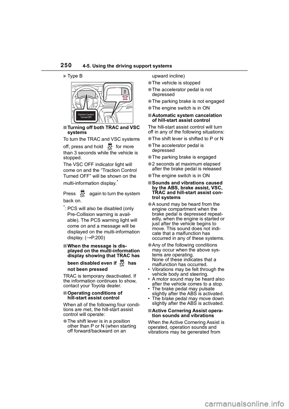
Ty p e B
■Turning off both TRAC and VSC
systems
To turn the TRAC and VSC systems
off, press and h old for more
than 3 seconds while the vehicle is
stopped.
The VSC OFF indicator light will
come on and the “Traction Control
Turned OFF” will be shown on the
multi-information display.
*
Press again to turn the system
back on.
*: PCS will also be disabled (only Pre-Collision warning is avail-
able). The PCS warning light will
come on and a message will be
displayed on the multi-information
display. ( P.200)
■When the message is dis-
played on the multi-information
display showing that TRAC has
been disabled even if has
not been pressed
TRAC is temporary deactivated. If
the information continues to show,
contact your Toyota dealer.
■Operating conditions of
hill-start assist control
When all of the following four condi-
tions are me t, the hill-start assist
control will operate:
●The shift lever is in a position
other than P or N (when starting
off forward/backward on an upward incline)
●The vehicle is stopped
●The accelerator pedal is not
depressed
●The parking brake is not engaged
●The engine switch is in ON
■Automatic system cancelation
of hill-start assist control
The hill-start assist control will turn
off in any of the fo llowing situations:
●The shift lever is shifted to P or N
●The accelerator pedal is
depressed
●The parking brake is engaged
●2 seconds at maximum elapsed
after the brake pedal is released
●The engine switch is in ON
■Sounds and vibrations caused
by the ABS, brake assist, VSC,
TRAC and hill-start assist con-
trol systems
●A sound may be heard from the
engine compartment when the
brake pedal is depressed repeat-
edly, when the engine is started or
just after the vehicle begins to
move. This sound does not indi-
cate that a malfunction has
occurred in any of these systems.
●Any of the following conditions
may occur when the above sys-
tems are operating.
None of these ind icates that a
malfunction has occurred.
• Vibrations may be felt through the
vehicle body and steering.
• A motor sound may be heard also after the vehicle comes to a stop.
• The brake pedal may pulsate
slightly after the ABS is activated.
• The brake pedal may move down slightly after the ABS is activated.
■Active Cornering Assist opera-
tion sounds and vibrations
When the Active Cornering Assist is
operated, operation sounds and
vibrations may be generated from
Page 258 of 468

2585-1. Using the air conditioning system and defogger
5-1.Using the air conditioning system and defogger
*: If equipped
The display and button positions will differ depending on the type of
the system.
Fan speed control switch
Temperature control switch
“MAX A/C” switch
“A/C” switch
Outside air mode switch
Recirculated air mode switch
Airflow mode control switch
Rear window defogger and outside rear view mirror defoggers
switch
*
Windshield defogger switch
On/off switch
Rear window defogger switch
*
*: If equipped
■Adjusting the temperature
setting
To adjust the temperature set-
ting, turn the temperature con-
trol switch clockwise (warm) or
counterclockwise (cool).If “A/C” switch is not pressed, the
system will blow ambient tempera-
ture air or heated air.
For quick cooling, press the “MAX
A/C” switch. The air conditioning
will automatically turn on and, if an
Manual air conditioning system*
Air conditioning controls
Page 263 of 468
2635-1. Using the air conditioning system and defogger
5
Interior features
*: If equipped
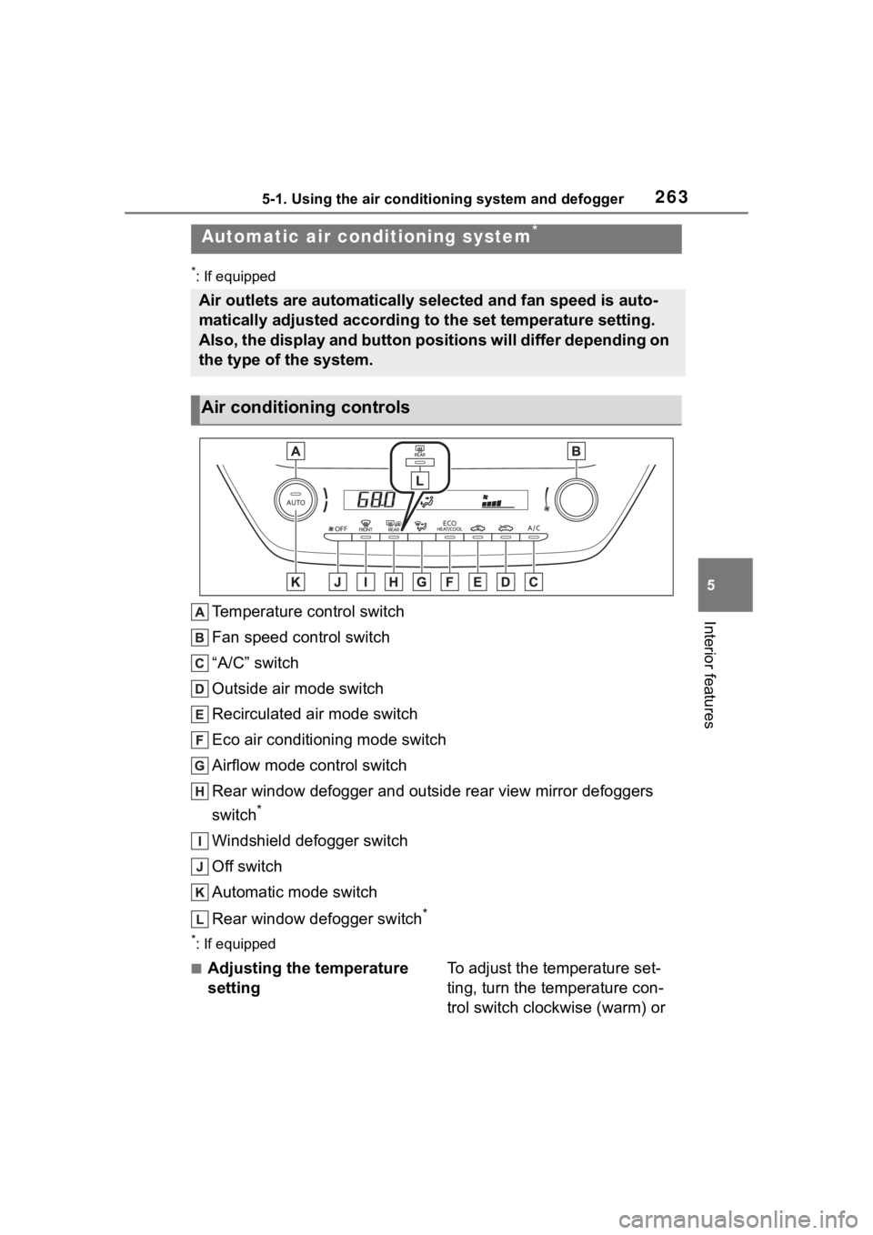
Temperature control switch
Fan speed control switch
“A/C” switch
Outside air mode switch
Recirculated air mode switch
Eco air conditioning mode switch
Airflow mode control switch
Rear window defogger and outside rear view mirror defoggers
switch
*
Windshield defogger switch
Off switch
Automatic mode switch
Rear window defogger switch
*
*: If equipped
■Adjusting the temperature
settingTo adjust the temperature set-
ting, turn the temperature con-
trol switch clockwise (warm) or
Automatic air conditioning system*
Air outlets are automatically selected and fan speed is auto-
matically adjusted according to the set temperature setting.
Also, the display and button positions will differ depending on
the type of the system.
Air conditioning controls
Page 283 of 468
2835-4. Other interior features
5
Interior features
●The portable device is being
charged with a cable connected
●There is foreign matter between
the charge area and portable
device
●Charging has caused the porta-
ble device to heat up
●The temperature around the
charging tray is 95°F (35°C) or
higher, such as in extreme heat
●The portable device is placed
with its charging side facing up
●The portable device is placed in
an area misaligned from the
charge area
●The portable device is larger
than the charging tray
●A foldable and portable device
is placed outside the charge
area
●The camera lens protrudes 0.12
in (3 mm) or more from the sur-
face of the portable device
●The vehicle is in an area where
strong electrical waves or noise
are emitted, such as near a tele-
vision tower, power plant, gaso-
line station, broadcasting
station, large display, airport,
etc.
●Any of the following objects that
is 0.08 in (2 mm) or thicker is
between the charging side of
the portable device and the
charge area
• Thick cases or covers
• A case or cover attached with an uneven or tilted surface, so
that the charging side is not flat
• Thick decorations
• Accessories, such as finger rings, straps, etc.
●When the portable device is in
contact with, or is covered by
any of the following metallic
objects:
• A card that has metal on it, such as aluminum foil, etc.
• A pack of cigarettes that includes aluminum foil
• A wallet or bag that is made of metal
• Coins
• A heating pad
• CDs, DVDs or other media
• A metal accessory
• A case or cover made of metal
• A case which has magnet in it on the charging side of the por-
table device.
●Electric wave type wireless
remote controls are being used
nearby
NOTICE
●2 or more portable devices are
placed on the charging tray at
the same time
If charging is abnormal or the
operation indicator light contin-
ues to flash for any other reason,
the wireless char ger may be mal-
functioning. Contact your Toyota
dealer.
Page 295 of 468
2956-2. Maintenance
6
Maintenance and care
■Resetting the message indicat-
ing maintenance is required
After the required maintenance is
performed according to the mainte-
nance schedule, please reset the
message.
To reset the messa ge, follow the
procedure described below:
4.2-inch display
1 Press or of the meter
control switch to select .
2 Press or to select “Vehi-
cle Settings” and then press and
hold .
3 Press or to select
“Scheduled Maintenance” and
then press .
4 Press or to select “Yes”
and then press .
A message will be displayed on the
multi-information display when the
reset procedure has been com-
pleted.
7-inch display
1 Press or of the meter
control switch to select .
2 Press or to select “Vehi-
cle Settings” and then press and
hold .
3 Press or to select
“Scheduled Maintenance” and
then press .
4 Press or to select “Yes”
and then press .
A message will be displayed on the
multi-information display when the
reset procedure has been com-
pleted.
You can perform some mainte-
nance procedures by yourself.
Please be aware that do-it-your-
self maintenance may affect
warranty coverage.
The use of Toyota repair manuals is
recommended.
For details about warranty cover-
age, refer to the separate “Owner’s
Warranty Informat ion Booklet” or
“Owner’s Manual Supplement”.
Do-it-yourself mainte-
nance
Page 310 of 468
3106-3. Do-it-yourself maintenance
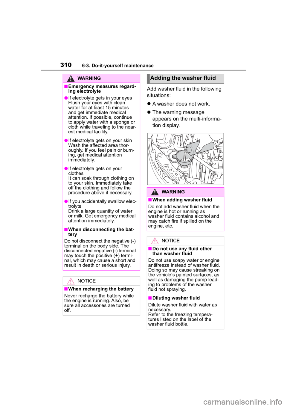
Add washer fluid in the following
situations:
A washer does not work.
The warning message
appears on the multi-informa-
tion display.
WARNING
■Emergency measures regard-
ing electrolyte
●If electrolyte gets in your eyes
Flush your eyes with clean
water for at least 15 minutes
and get immediate medical
attention. If possible, continue
to apply water with a sponge or
cloth while traveling to the near-
est medical facility.
●If electrolyte gets on your skin
Wash the affected area thor-
oughly. If you fee l pain or burn-
ing, get medical attention
immediately.
●If electrolyte gets on your
clothes
It can soak through clothing on
to your skin. Immediately take
off the clothing and follow the
procedure above if necessary.
●If you accidentally swallow elec-
trolyte
Drink a large quantity of water
or milk. Get emergency medical
attention immediately.
■When disconnecting the bat-
tery
Do not disconnect the negative (-)
terminal on the body side. The
disconnected negative (-) terminal
may touch the positive (+) termi-
nal, which may cause a short and
result in death or serious injury.
NOTICE
■When recharging the battery
Never recharge the battery while
the engine is running. Also, be
sure all accessories are turned
off.
Adding the washer fluid
WARNING
■When adding washer fluid
Do not add washer fluid when the
engine is hot or running as
washer fluid contains alcohol and
may catch fire if spilled on the
engine, etc.
NOTICE
■Do not use any fluid other
than washer fluid
Do not use soapy water or engine
antifreeze instead of washer fluid.
Doing so may cause streaking on
the vehicle’s painted surfaces, as
well as damaging the pump lead-
ing to problems of the washer
fluid not spraying.
■Diluting washer fluid
Dilute washer fluid with water as
necessary.
Refer to the freezing tempera-
tures listed on the label of the
washer fluid bottle.
Page 313 of 468
3136-3. Do-it-yourself maintenance
6
Maintenance and care
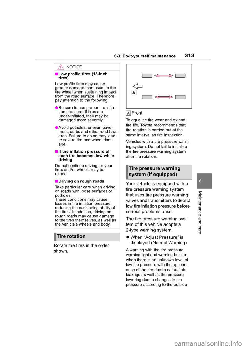
Rotate the tires in the order
shown.Front
To equalize tire w
ear and extend
tire life, Toyota recommends that
tire rotation is carried out at the
same interval as tire inspection.
Vehicles with a tire pressure warn-
ing system: Do not fa il to initialize
the tire pressure warning system
after tire rotation.
Your vehicle is equipped with a
tire pressure warning system
that uses tire pressure warning
valves and transmitters to detect
low tire inflation pressure before
serious problems arise.
The tire pressure warning sys-
tem of this vehicle adopts a
2-type warning system.
When “Adjust Pressure” is
displayed (Normal Warning)
A warning with the tire pressure
warning light and warning buzzer
when there is an unknown level of
low tire pressure with the appear-
ance of the tire due to natural air
leakage as well as the pressure
lowering due to changes in the
pressure according to the outside
NOTICE
■Low profile tires (18-inch
tires)
Low profile tires may cause
greater damage th an usual to the
tire wheel when sustaining impact
from the road surface. Therefore,
pay attention to the following:
●Be sure to use pro per tire infla-
tion pressure. If tires are
under-inflated, they may be
damaged more severely.
●Avoid potholes, uneven pave-
ment, curbs and other road haz-
ards. Failure to do so may lead
to severe tire and wheel dam-
age.
■If tire inflation pressure of
each tire becomes low while
driving
Do not continue driving, or your
tires and/or wheels may be
ruined.
■Driving on rough roads
Take particular care when driving
on roads with loose surfaces or
potholes.
These conditions may cause
losses in tire inf lation pressure,
reducing the cushio ning ability of
the tires. In addit ion, driving on
rough roads may cause damage
to the tires themselves, as well as
the vehicle’s wheels and body.
Tire rotation
Tire pressure warning
system (if equipped)
Page 314 of 468

3146-3. Do-it-yourself maintenance
temperature. (Ways of coping:
P.360, 397)
When “Immediately Check
Tire when Safe” is displayed
(Emergency Warning)
A warning with the tire pressure
warning light and warning buzzer
when there is a known level of low
tire pressure with the appearance
of the tire due to pressure suddenly
lowering. (Ways of coping: P.360,
370)
However, the system may not be
able to detect sud den tire ruptures
(bursting, etc.).
The tire pressure detected by the
tire pressure warning system can
be displayed on the multi-informa-
tion display.
■How to change the unit
4.2-inch display
1 Park the vehicle in a safe
place and turn the engine
switch off.
Changing the unit cannot be per-
formed while the vehicle is moving.
2Turn the engine switch to
ON. 3
Select of the multi-infor-
mation display and then
press .
4 Press or to select
“Vehicle Settings” and then
press and hold .
5 Press or to select
“TPWS setting” and then
press .
6 Press or to select
“Pressure unit setting”.
7 Press or to select the
desired unit and then press
.
7-inch display
1 Park the vehicle in a safe
place and turn the engine
switch off.
Changing the unit cannot be per-
formed while the vehicle is moving.
2Turn the engine switch to
ON.
3 Select of the multi-infor-
mation display and then
press .
4 Press or to select
“Vehicle Settings” and then
press and hold .
5 Press or to select
“TPWS setting” and then
press .