2023 TOYOTA COROLLA HYBRID power outlet
[x] Cancel search: power outletPage 280 of 496

2805-1. Using the air conditioning system and defogger
■Defogging the rear window
and outside rear view mir-
rors
Vehicles without outside rear
view mirror defoggers
A defogger is used to defog the
rear window.
Press the rear window defogger
switch.
The defogger will automatically turn
off after a while.
When the rear window defogger
switch is on, the indicator illumi-
nates on the rear window defogger
switch.
Vehicles with outside rear
view mirror defoggers
Defoggers are used to defog the
rear window, and to remove
raindrops, dew and frost from
the outside rear view mirrors.
Press the rear window and out-
side rear view mirror defoggers
switch.
The defoggers will automatically
turn off after a while.
When the rear window and outside
rear view mirror defoggers switch is
on, the indicator illuminates on the
rear window and ou tside rear view
mirror defoggers switch.
■Eco air conditioning mode
The air conditioning is controlled
with low fuel consumption priori-
tized such as reducing fan
speed, etc.
Press the eco air conditioning
mode switch.
When the eco air conditioning
mode is on, the indicator illumi-
nates on the eco air conditioning
mode switch.
■When the outside temperature
exceeds 75°F (24°C) and the air
conditioning system is on
●In order to reduce the air condi-
tioning power consumption, the air
conditioning system may switch to
recirculated air mode automati-
cally. This may also reduce fuel
consumption.
●Recirculated air mode is selected
as a default mode when the power
switch is turned to ON.
●It is possible to switch to outside
air mode at any time by pressing
the outside air mode switch.
■Fogging up of the windows
●The windows will easily fog up
when the humidity in the vehicle is
high. Turning “A/C” on will dehu-
midify the air from the outlets and
defog the windshield effectively.
●If you turn “A/C” off, the windows
may fog up more easily.
●The windows may fog up if the
recirculated air mode is used.
■When driving on dusty roads
Close all windows. If dust thrown up
by the vehicle is still drawn into the
vehicle after closing the windows, it
is recommended that the air intake
mode be set to outside air mode and
the fan speed to a ny setting except
off.
■Outside/recirculated air mode
●Setting to the recirculated air
mode temporarily is recom-
mended in preventing dirty air
from entering the vehicle interior
and helping to c ool the vehicle
when the outside air temperature
is high.
●Outside/recirculated air mode may
automatically switch depending on
Page 292 of 496
2925-4. Other interior features
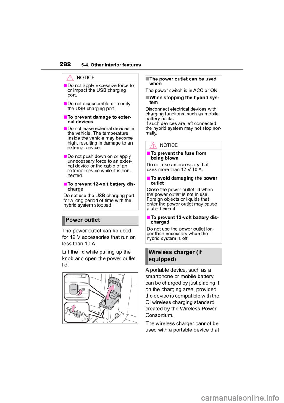
The power outlet can be used
for 12 V accessories that run on
less than 10 A.
Lift the lid while pulling up the
knob and open the power outlet
lid.
■The power outlet can be used
when
The power switch is in ACC or ON.
■When stopping the hybrid sys-
tem
Disconnect electrical devices with
charging functions, such as mobile
battery packs.
If such devices are left connected,
the hybrid system may not stop nor-
mally.
A portable device, such as a
smartphone or mobile battery,
can be charged by just placing it
on the charging area, provided
the device is compatible with the
Qi wireless charging standard
created by the Wireless Power
Consortium.
The wireless charger cannot be
used with a portable device that
NOTICE
●Do not apply excessive force to
or impact the USB charging
port.
●Do not disassemble or modify
the USB charging port.
■To prevent damage to exter-
nal devices
●Do not leave external devices in
the vehicle. The temperature
inside the vehicle may become
high, resulting in damage to an
external device.
●Do not push down on or apply
unnecessary force to an exter-
nal device or the cable of an
external device while it is con-
nected.
■To prevent 12-volt battery dis-
charge
Do not use the USB charging port
for a long period of time with the
hybrid system stopped.
Power outlet
NOTICE
■To prevent the fuse from
being blown
Do not use an accessory that
uses more than 12 V 10 A.
■To avoid damaging the power
outlet
Close the power outlet lid when
the power outlet is not in use.
Foreign objects or liquids that
enter the power outlet may cause
a short circuit.
■To prevent 12-volt battery dis-
charged
Do not use the p ower outlet lon-
ger than necessary when the
hybrid system is off.
Wireless charger (if
equipped)
Page 392 of 496
3927-2. Steps to take in an emergency
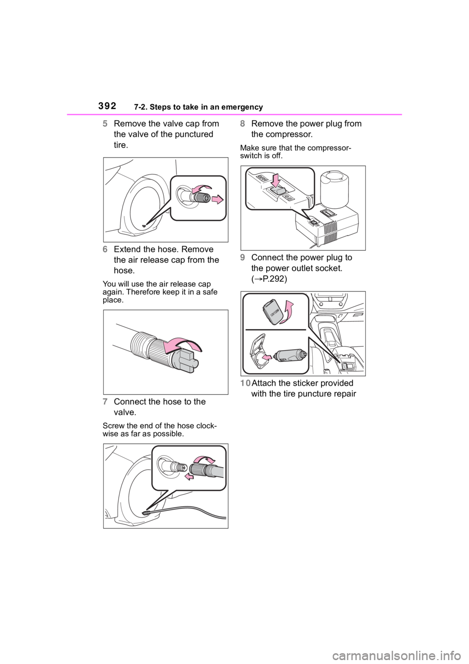
5Remove the valve cap from
the valve of the punctured
tire.
6 Extend the hose. Remove
the air release cap from the
hose.
You will use the air release cap
again. Therefore keep it in a safe
place.
7Connect the hose to the
valve.
Screw the end of the hose clock-
wise as far as possible.
8Remove the power plug from
the compressor.
Make sure that the compressor-
switch is off.
9Connect the power plug to
the power outlet socket.
( P.292)
10Attach the sticker provided with the tire puncture repair
Page 394 of 496
3947-2. Steps to take in an emergency
pressure about 1 to 5 min-
utes after the switch is turned
on.
Turn the compressor switch off and
then check the tire inflation pres-
sure. Being careful not to over
inflate, check and repeat the infla-
tion procedure unt il the specified
tire inflation pressure is reached.
The tire can be inflated for about 5
to 20 minutes (depending on the
outside temperature). If the tire
inflation pressure is still lower than
the specified point after inflation for
25 minutes, the tire is too damaged
to be repaired. Turn the compres-
sor switch off and contact your Toy-
ota dealer.
If the tire inflation pressure exceeds
thespecified air pressure, let out
some airto adjust the tire inflation
pressure. ( P.395, 426)
15 With the compressor switch
off, disconnect the hose from
the valve on the tire and then
pull out the power plug from
the power outlet socket.
Some sealant may leak when the
hose is removed.
16 Install the valve cap onto the
valve of the emergency
repaired tire.
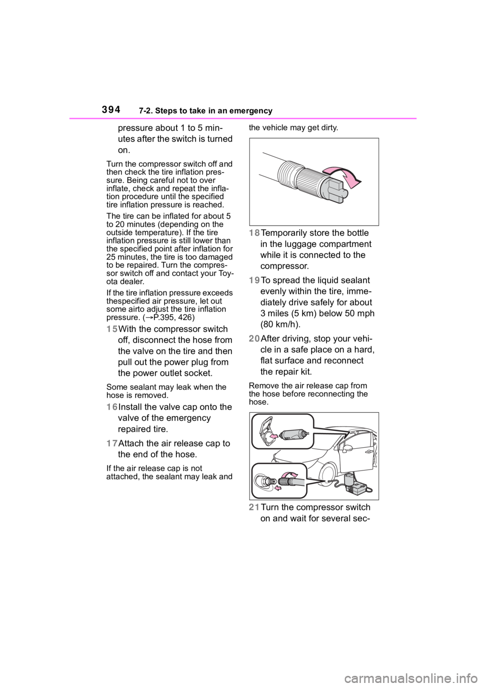
17 Attach the air release cap to
the end of the hose.
If the air release cap is not
attached, the sealant may leak and the vehicle may get dirty.
18Temporarily store the bottle
in the luggage compartment
while it is connected to the
compressor.
19To spread the liquid sealant evenly within the tire, imme-
diately drive safely for about
3 miles (5 km) below 50 mph
(80 km/h).
20After driving, stop your vehi- cle in a safe place on a hard,
flat surface and reconnect
the repair kit.
Remove the air release cap from
the hose before reconnecting the
hose.
21Turn the compressor switch
on and wait for several sec-
Page 474 of 496

474Alphabetical Index
P
Panic mode ............................. 124
Parking brakeOperation ............................. 183
Parking brake engaged warning buzzer ................................ 185
Warning light ........................ 379
Warning message ................ 185
Parking lights Light switch .......................... 189
Replacing light bulbs ............ 357
PCS (Pre-Collision System)... 207 Function ............................... 208
Warning light ........................ 377
PDA (Proactive driving assist) [PDA (Proactive driving assist)]............................................... 228
Personal lights ....................... 286 Wattage ................................ 428
Power control unit .................... 82
Power control unit coolant Capacity ............................... 423
Checking .............................. 320
Preparing and c hecking before
winter.................................. 273
Power outlet ............................ 292
Power steering (Electric power steering system)................... 266Warning light ........................ 375
Power switch .................. 170, 172 Auto power off function ........ 176
Changing the power switch modes ................................ 176
Power switch ( engine switch)
If your vehicle has to be stopped in an emergency................. 363
Power windows Door lock linked window opera-tion ..................................... 151
Jam protection function ........ 150
Operation ............................. 150 Window lock switch ..............152
Pre-Collision System (PCS) ...207 Function................................208
Warning light.........................377
Predictive efficient drive .........80
R
Radiator ...................................321
RCTA Function................................254
RCTA function .........................255
Rear Cross Traffic Alert (RCTA) ...............................................254
Rear seats ...............................142 Head restraints .....................144
Rear side marker lights Light switch...........................189
Replacing light bulbs ............357
Wattage ................................428
Rear turn signal lights Replacing light bulbs ....357, 358
Turn signal lever ...................182
Wattage ................................428
Rear view mirror Inside rear view mirror ..........147
Outside rear view mirrors .....148
Rear window defogger ...........280
Refueling Capacity ...............................421
Fuel types .............................421
Opening the fuel tank cap ....196
Regenerative braking ...............78
Replacing Electronic key battery ...........350
Fuses....................................354
Light bulbs ............................356
Tires......................................398
Wireless remote control battery...........................................350
Reporting safety defects for Canadian owners ..................454