2023 TOYOTA COROLLA HYBRID check engine
[x] Cancel search: check enginePage 6 of 496
6
properly or the danger that it
may work in situations where it
should not be working.
Installing electronic devices and
radios increases the risk of
cyber attacks through the
installed parts, which may lead
to unexpected accidents and
leakage of personal informa-
tion. Toyota does not make any
guarantees for problems caused
by installing non-genuine Toyota
products.
The installation of a mobile
two-way radio system in your
vehicle could affect electronic
systems such as:
Multiport fuel injection sys-
tem/sequential multiport fuel
injection system
Toyota Safety Sense 3.0
Anti-lock brake system
SRS airbag system
Seat belt pretensioner system
Be sure to check with your Toy-
ota dealer for precautionary
measures or special instructions
regarding installation of a mobile
two-way radio system.
High voltage parts and cables
on the hybrid vehicles emit approximately the same amount
of electromagnetic waves as the
conventional gasoline powered
vehicles or home electronic
appliances despite of their elec-
tromagnetic shielding.
Unwanted noise may occur in
the reception of the mobile
two-way radio.
This vehicle is equipped with
sophisticated computers that
record certain data regarding
vehicle controls and operations.
Data recorded by the comput-
ers
*1
Certain data, such as the following,
is recorded dependi ng on the oper-
ation timing and status of each
function.
• Basic vehicle behavior related data (engine speed/electric motor
speed, accelerator/brake pedal
operation, vehicle speed, etc.)
• Operating state of the driving support systems (recorded during
system operation, includes basic
vehicle behavior related data)
• Driving support system sensor data
• Image data (images from the front, rear and side cameras)
*2
• Location information
These computers do not record
conversations, sounds, or
images of the inside of the vehi-
cle.
Cyber Attack Risk
Installation of a mobile
two-way radio system
Vehicle data recording
Page 14 of 496
14Pictorial index
Fuel filler door .................................................................... P.196
Refueling method ............................................... .................. P.197
Fuel type/fuel tan k capacity ................................... .............. P.421
Tires.......................................................... ........................... P.325
Tire size/inflation pressure ................................... ................ P.426
Winter tires/tire chains ....................................... .................. P.273
Checking/rotation/tire pressur e warning system ..................P.325
Coping with flat tires......................................... ............ P.387, 398
Hood ........................................................... ......................... P.316
Opening ............................................................................... P.316
Engine oil ..................................................... ........................ P.422
Coping with overheating ...................................................... P.414
Headlights/daytime running lights .............................. ..... P.189
Turn signal lights/parking lights .............................. ......... P.189
Front side marker lights ....................................... ............. P.189
LED accent lights
*2............................................................ P.1 89
Stop lights/tail lights/rear side marker lights/turn signal lig hts
P. 1 8 9
License plate lights........................................... ................. P.189
Tail lights
*2............................................................... ........... P.189
Back-up lights
Shifting the shift position to R ............................... ............... P.180
Side turn signal lights
*2..................................................... P.182
*1: Vehicles with a smart key system
*2: If equipped
Light bulbs of the exterior lights for driving
(Replacing method: P.356, Watts: P.428)
Page 97 of 496
972-1. Instrument cluster
2
Vehicle status information and indicators
■Engine speed
On hybrid electric vehicles, engine
speed is precisely controlled in
order to help improve fuel efficiency
and reduce exhaust emissions etc.
There are times when the engine
speed that is displayed may differ
even when vehicle operation and
driving conditions are the same.
■Outside temperature display
●In the following si tuations, the cor-
rect outside tempe rature may not
be displayed, or the display may
take longer than normal to
change:
• When stopped, or driving at low
speeds (less than 12 mph [20
km/h])
• When the outside temperature
has changed suddenly (at the
entrance/exit of a garage, tunnel,
etc.)
●When “--” or “E” is displayed, the
system may be malfunctioning.
Take your vehicle to your Toyota
dealer.
■Liquid crystal display
P. 1 0 3
■Customization
The gauges and meters can be cus-
tomized in of the multi-informa-
tion display. ( P.442)
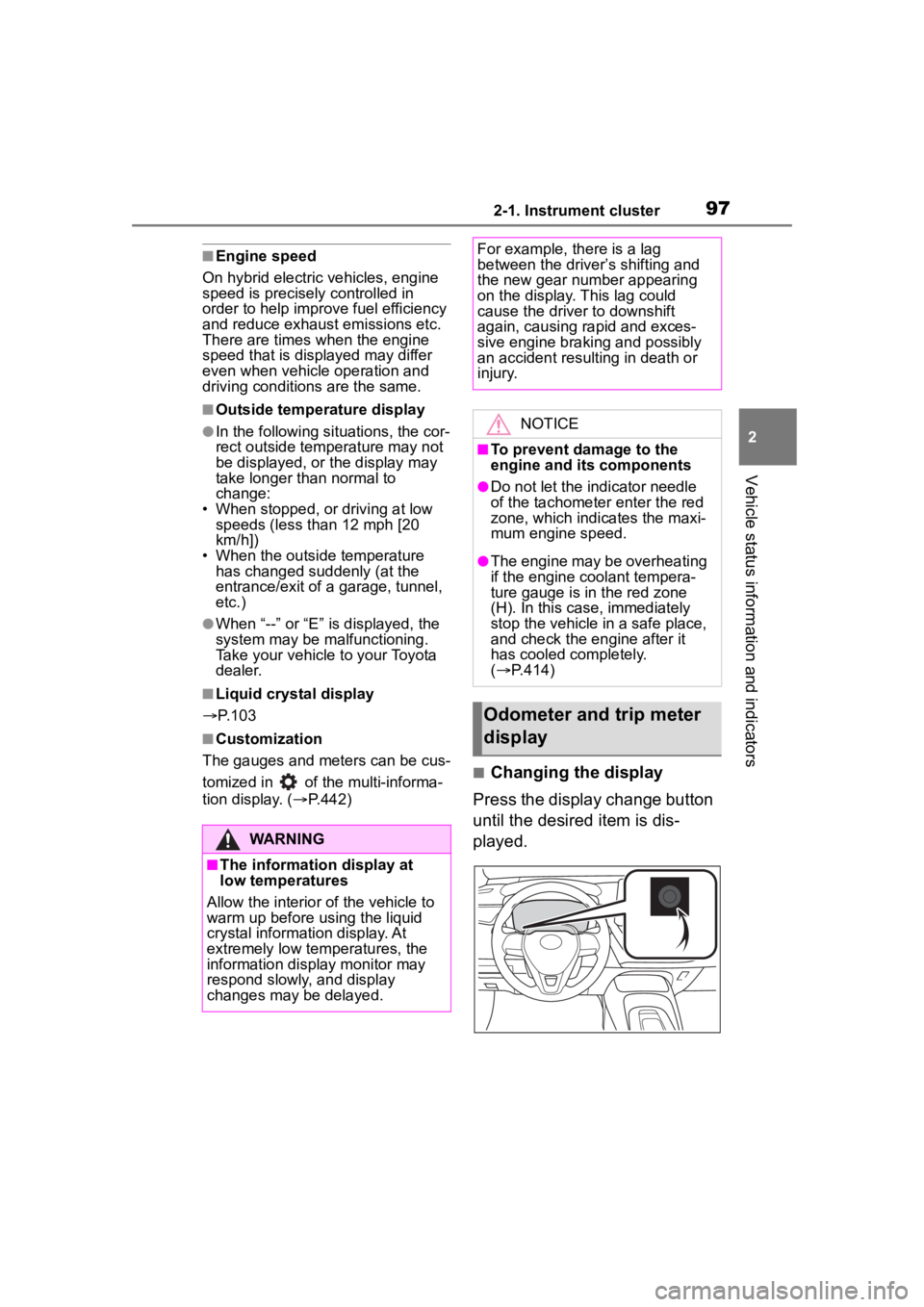
■Changing the display
Press the display change button
until the desired item is dis-
played.
WARNING
■The information display at
low temperatures
Allow the interior of the vehicle to
warm up before u sing the liquid
crystal informat ion display. At
extremely low temperatures, the
information display monitor may
respond slowly, and display
changes may be delayed.
For example, there is a lag
between the driver’s shifting and
the new gear number appearing
on the display. This lag could
cause the driver to downshift
again, causing rapid and exces-
sive engine braking and possibly
an accident resulting in death or
injury.
NOTICE
■To prevent damage to the
engine and its components
●Do not let the indicator needle
of the tachometer enter the red
zone, which indicates the maxi-
mum engine speed.
●The engine may be overheating
if the engine coolant tempera-
ture gauge is in the red zone
(H). In this case, immediately
stop the vehicle in a safe place,
and check the engine after it
has cooled completely.
( P.414)
Odometer and trip meter
display
Page 101 of 496
1012-1. Instrument cluster
2
Vehicle status information and indicators
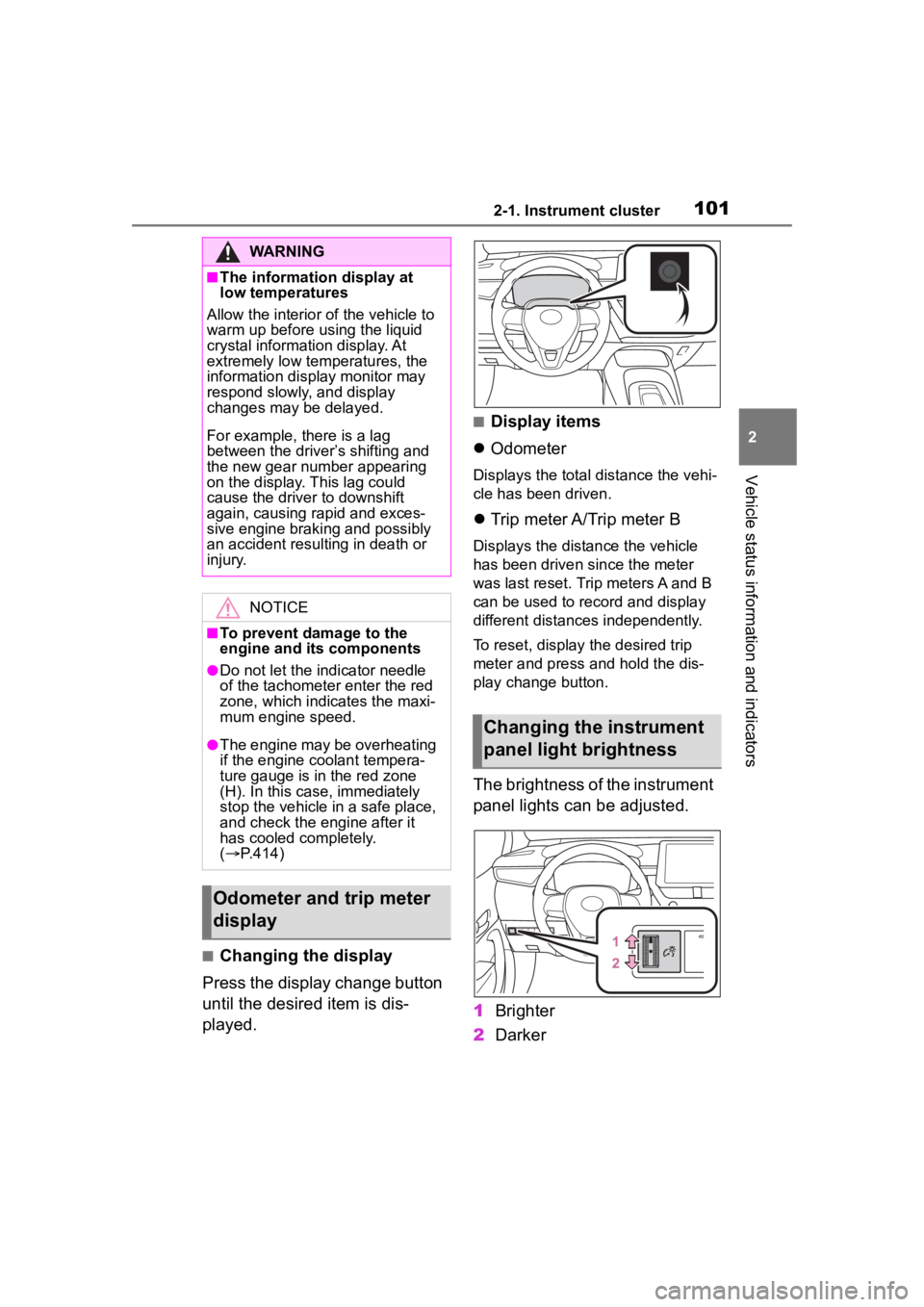
■Changing the display
Press the display change button
until the desired item is dis-
played.
■Display items
Odometer
Displays the total distance the vehi-
cle has been driven.
Trip meter A/Trip meter B
Displays the distance the vehicle
has been driven since the meter
was last reset. Trip meters A and B
can be used to record and display
different distances independently.
To reset, display the desired trip
meter and press and hold the dis-
play change button.
The brightness of the instrument
panel lights can be adjusted.
1 Brighter
2 Darker
WARNING
■The information display at
low temperatures
Allow the interior of the vehicle to
warm up before u sing the liquid
crystal informat ion display. At
extremely low temperatures, the
information display monitor may
respond slowly, and display
changes may be delayed.
For example, there is a lag
between the driver’s shifting and
the new gear number appearing
on the display. This lag could
cause the driver to downshift
again, causing rapid and exces-
sive engine braking and possibly
an accident resulting in death or
injury.
NOTICE
■To prevent damage to the
engine and its components
●Do not let the i ndicator needle
of the tachomete r enter the red
zone, which indicates the maxi-
mum engine speed.
●The engine may be overheating
if the engine coolant tempera-
ture gauge is in the red zone
(H). In this case, immediately
stop the vehicle in a safe place,
and check the engine after it
has cooled completely.
( P.414)
Odometer and trip meter
display
Changing the instrument
panel light brightness
Page 116 of 496
1162-1. Instrument cluster
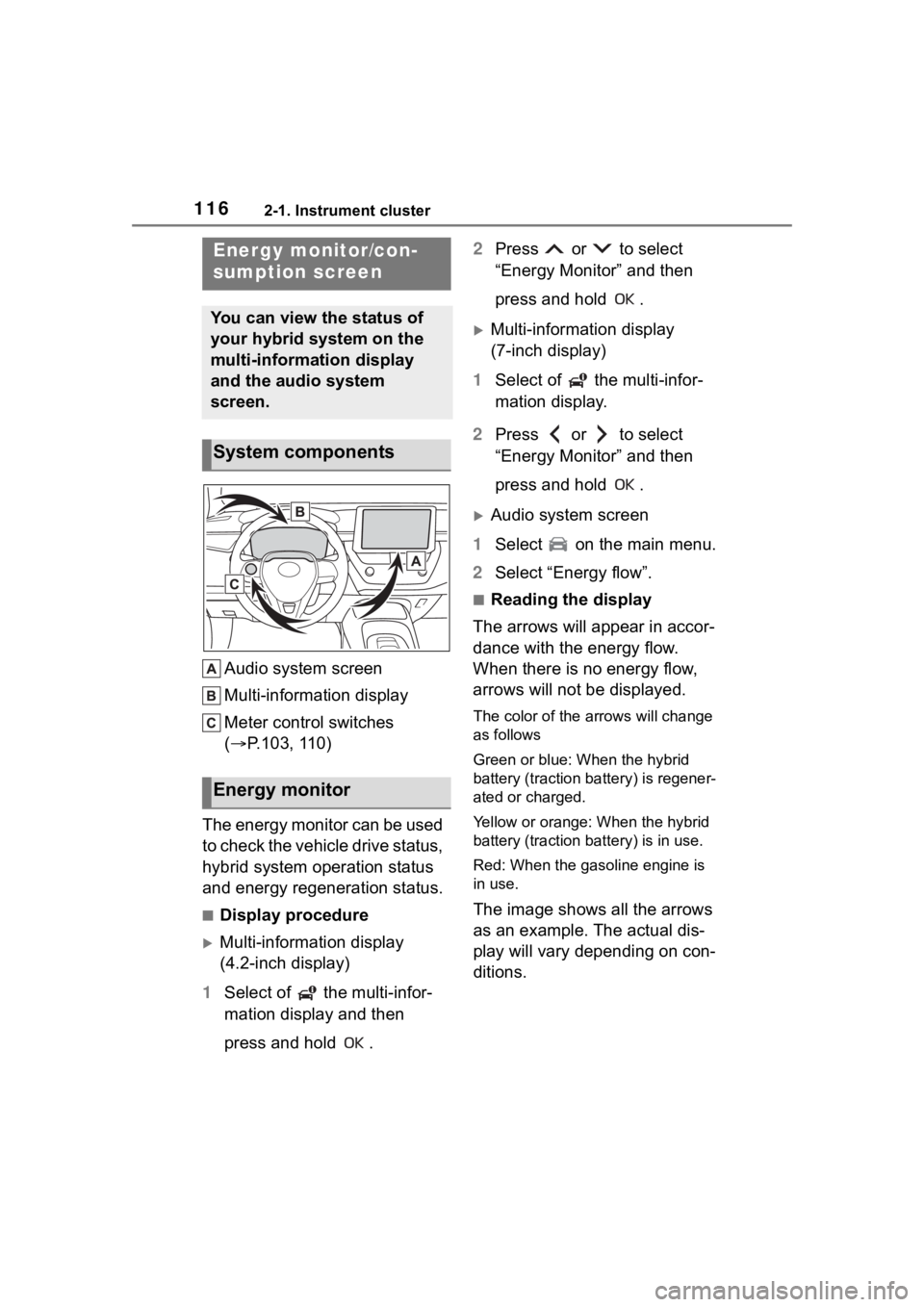
Audio system screen
Multi-information display
Meter control switches
(P.103, 110)
The energy monitor can be used
to check the vehicle drive status,
hybrid system operation status
and energy regeneration status.
■Display procedure
Multi-information display
(4.2-inch display)
1 Select of the multi-infor-
mation display and then
press and hold . 2
Press or to select
“Energy Monitor” and then
press and hold .
Multi-information display
(7-inch display)
1 Select of the multi-infor-
mation display.
2 Press or to select
“Energy Monitor” and then
press and hold .
Audio system screen
1 Select on the main menu.
2 Select “Energy flow”.
■Reading the display
The arrows will appear in accor-
dance with the energy flow.
When there is no energy flow,
arrows will not be displayed.
The color of the arrows will change
as follows
Green or blue: When the hybrid
battery (traction battery) is regener-
ated or charged.
Yellow or orange: When the hybrid
battery (traction battery) is in use.
Red: When the gasoline engine is
in use.
The image shows all the arrows
as an example. The actual dis-
play will vary depending on con-
ditions.
Energy monitor/con-
sumption screen
You can view the status of
your hybrid system on the
multi-information display
and the audio system
screen.
System components
Energy monitor
Page 162 of 496
1624-1. Before driving
WARNING
●After driving through a puddle,
lightly depress the brake pedal
to make sure that the brakes
are functioning properly. Wet
brake pads may prevent the
brakes from functioning prop-
erly. If the brakes on only one
side are wet and not functioning
properly, steering control may
be affected.
■When shifting the shift lever
●Do not let the vehicle roll back-
ward while a forward driving
position is selected, or roll for-
ward while the shift lever is in R.
Doing so may result in an acci-
dent or damage to the vehicle.
●Do not shift the shift lever to P
while the vehicle is moving.
Doing so can damage the trans-
mission and may result in a loss
of vehicle control.
●Do not shift the shift lever to R
while the vehicle is moving for-
ward.
Doing so can damage the trans-
mission and may result in a loss
of vehicle control.
●Do not shift the shift lever to a
driving position while the vehicle
is moving backward.
Doing so can damage the trans-
mission and may result in a loss
of vehicle control.
●Moving the shift lever to N while
the vehicle is moving will disen-
gage the hybrid system. Engine
braking is not available with the
hybrid system disengaged.
●Be careful not to shift the shift
lever with the accelerator pedal
depressed. Shifting the shift
lever to any positions other than
P or N may lead to unexpected
rapid acceleration of the vehicle
that may cause an accident and
result in death or serious injury.
■If you hear a squealing or
scraping noise (brake pad
wear indicators)
Have the brake pads checked and
replaced by your Toyota dealer as
soon as possible.
Rotor damage may result if the
pads are not replaced when
needed.
It is dangerous to drive the vehicle
when the wear limits of the brake
pads and/or those of the brake
discs are exceeded.
■When the vehicle is stopped
●Do not depress the accelerator
pedal unnecessarily.
If the shift lever is any position
other than P or N, the vehicle
may accelerate suddenly and
unexpectedly, causing an acci-
dent.
●In order to prevent accidents
due to the vehic le rolling away,
always keep depressing the
brake pedal while stopped with
the “READY” indicator is illumi-
nated, and apply the parking
brake as necessary.
●If the vehicle is stopped on an
incline, in order to prevent acci-
dents caused by the vehicle roll-
ing forward or backward, always
depress the brake pedal and
securely apply the parking
brake as needed.
Page 165 of 496

1654-1. Before driving
4
Driving
When the following unusual
operation is performed with the
accelerator pedal depressed,
the hybrid system output may be
restrained.
When the shift lever is shifted
to R
*.
When the shift lever is shifted
from P or R to forward drive
shift position such as D
*.
When the system op erates, a mes-
sage appears on the multi-informa-
tion display. Read the message and
follow the instruction.
*: Depending on the situation, the shift position may not be
changed.
■Drive-Start Control (DSC)
When the TRAC is turned off
( P.267), sudden start restraint
control also does not operate. If
your vehicle have trouble escaping
from the mud or fr esh snow due to
sudden start restraint control opera-
tion, deactivate TRAC ( P.267) so
that the vehicle may become able to
escape from the mud or fresh snow.NOTICE
●Engine damage caused by
water immersion
In the event that you drive on a
flooded road an d the vehicle
becomes flooded or stuck in mud
or sand, be sure to have your Toy-
ota dealer check the following:
●Brake function
●Changes in quantity and quality
of oil and fluid used for the
engine, hybrid transmission,
etc.
●Lubricant condition for the bear-
ings and suspension joints
(where possible), and the func-
tion of all joints , bearings, etc.
Sudden start restraint
control (Drive-Start Con-
trol [DSC])
Page 170 of 496
1704-2. Driving procedures
4-2.Driving procedures
1Check that the parking brake
is set. ( 183)
2 Check that the shift lever is in
P.
3 Firmly depress the brake
pedal.
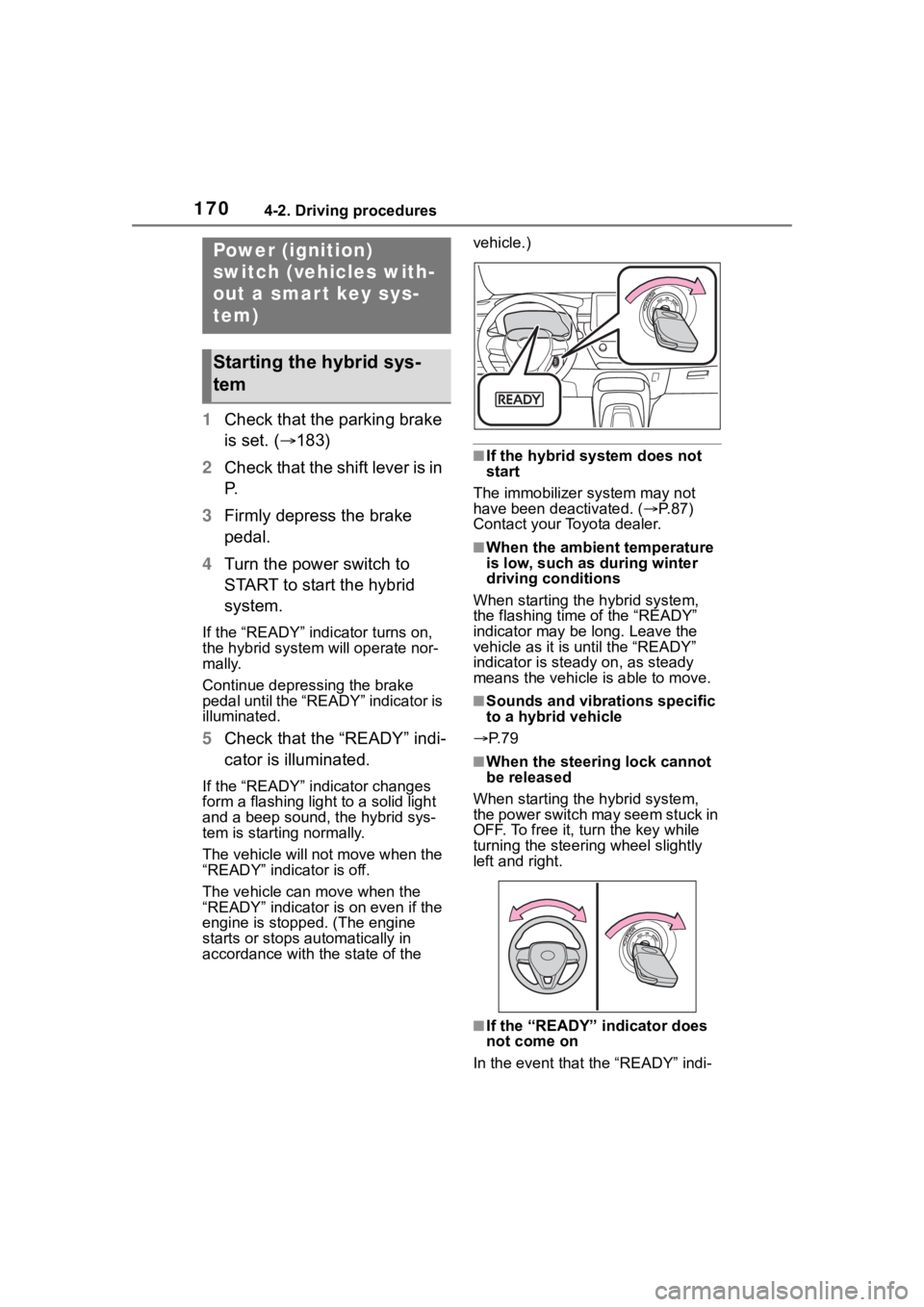
4 Turn the power switch to
START to start the hybrid
system.
If the “READY” indicator turns on,
the hybrid system will operate nor-
mally.
Continue depressing the brake
pedal until the “READY” indicator is
illuminated.
5Check that the “READY” indi-
cator is illuminated.
If the “READY” indicator changes
form a flashing light to a solid light
and a beep sound, the hybrid sys-
tem is starting normally.
The vehicle will not move when the
“READY” indicator is off.
The vehicle can move when the
“READY” indicator i s on even if the
engine is stopped. (The engine
starts or stops automatically in
accordance with the state of the vehicle.)
■If the hybrid system does not
start
The immobilizer system may not
have been deactivated. ( P. 8 7 )
Contact your Toyota dealer.
■When the ambient temperature
is low, such as during winter
driving conditions
When starting the hybrid system,
the flashing time of the “READY”
indicator may be long. Leave the
vehicle as it is until the “READY”
indicator is steady on, as steady
means the vehicle is able to move.
■Sounds and vibrations specific
to a hybrid vehicle
P. 7 9
■When the steering lock cannot
be released
When starting the hybrid system,
the power switch may seem stuck in
OFF. To free it, turn the key while
turning the steering wheel slightly
left and right.
■If the “READY” indicator does
not come on
In the event that the “READY” indi-
Power (ignition)
switch (vehicles with-
out a smart key sys-
tem)
Starting the hybrid sys-
tem