2023 TOYOTA COROLLA HYBRID ECO mode
[x] Cancel search: ECO modePage 24 of 496
241-1. For safe use
1-1.For safe use
Use only floor mats designed
specifically for vehicles of the
same model and model year as
your vehicle. Fix them securely
in place onto the carpet.
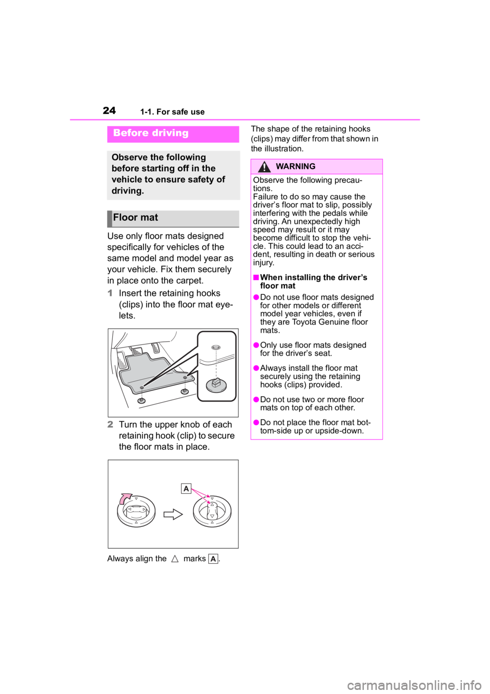
1Insert the retaining hooks
(clips) into the floor mat eye-
lets.
2 Turn the upper knob of each
retaining hook (clip) to secure
the floor mats in place.
Always align the marks . The shape of the retaining hooks
(clips) may differ from that shown in
the illustration.
Before driving
Observe the following
before starting off in the
vehicle to ensure safety of
driving.
Floor mat
WARNING
Observe the following precau-
tions.
Failure to do so may cause the
driver’s floor mat to slip, possibly
interfering with t
he pedals while
driving. An unexpectedly high
speed may result or it may
become difficult to stop the vehi-
cle. This could lead to an acci-
dent, resulting in death or serious
injury.
■When installing the driver’s
floor mat
●Do not use floor mats designed
for other models or different
model year vehicles, even if
they are Toyota Genuine floor
mats.
●Only use floor mats designed
for the driver’s seat.
●Always install the floor mat
securely using the retaining
hooks (clips) provided.
●Do not use two or more floor
mats on top of each other.
●Do not place the floor mat bot-
tom-side up or upside-down.
Page 64 of 496
641-2. Child safety
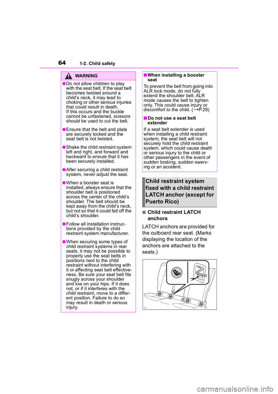
■Child restraint LATCH
anchors
LATCH anchors are provided for
the outboard rear seat. (Marks
displaying the location of the
anchors are attached to the
seats.)
WARNING
●Do not allow children to play
with the seat belt. If the seat belt
becomes twisted around a
child’s neck, it may lead to
choking or other serious injuries
that could result in death.
If this occurs and the buckle
cannot be unfastened, scissors
should be used to cut the belt.
●Ensure that the belt and plate
are securely locked and the
seat belt is not twisted.
●Shake the child restraint system
left and right, and forward and
backward to ensure that it has
been securely installed.
●After securing a child restraint
system, never adjust the seat.
●When a booster seat is
installed, always ensure that the
shoulder belt is positioned
across the center of the child’s
shoulder. The belt should be
kept away from the child’s neck,
but not so that it could fall off the
child’s shoulder.
●Follow all installation instruc-
tions provided by the child
restraint system manufacturer.
●When securing some types of
child restraint s ystems in rear
seats, it may not be possible to
properly use the seat belts in
positions next to the child
restraint without interfering with
it or affecting seat belt effective-
ness. Be sure your seat belt fits
snugly across your shoulder
and low on your hips. If it does
not, or if it interferes with the
child restraint, move to a differ-
ent position. Failure to do so
may result in death or serious
injury.
■When installing a booster
seat
To prevent the belt from going into
ALR lock mode, do not fully
extend the shoulder belt. ALR
mode causes the belt to tighten
only. This could cause injury or
discomfort to the child. (
P. 2 9 )
■Do not use a seat belt
extender
If a seat belt extender is used
when installing a child restraint
system, the seat belt will not
securely hold the child restraint
system, which could cause death
or serious injury to the child or
other passengers in the event of
sudden braking, sudden swerv-
ing or an accident.
Child restraint system
fixed with a child restraint
LATCH anchor (except for
Puerto Rico)
Page 82 of 496
821-4. Hybrid system
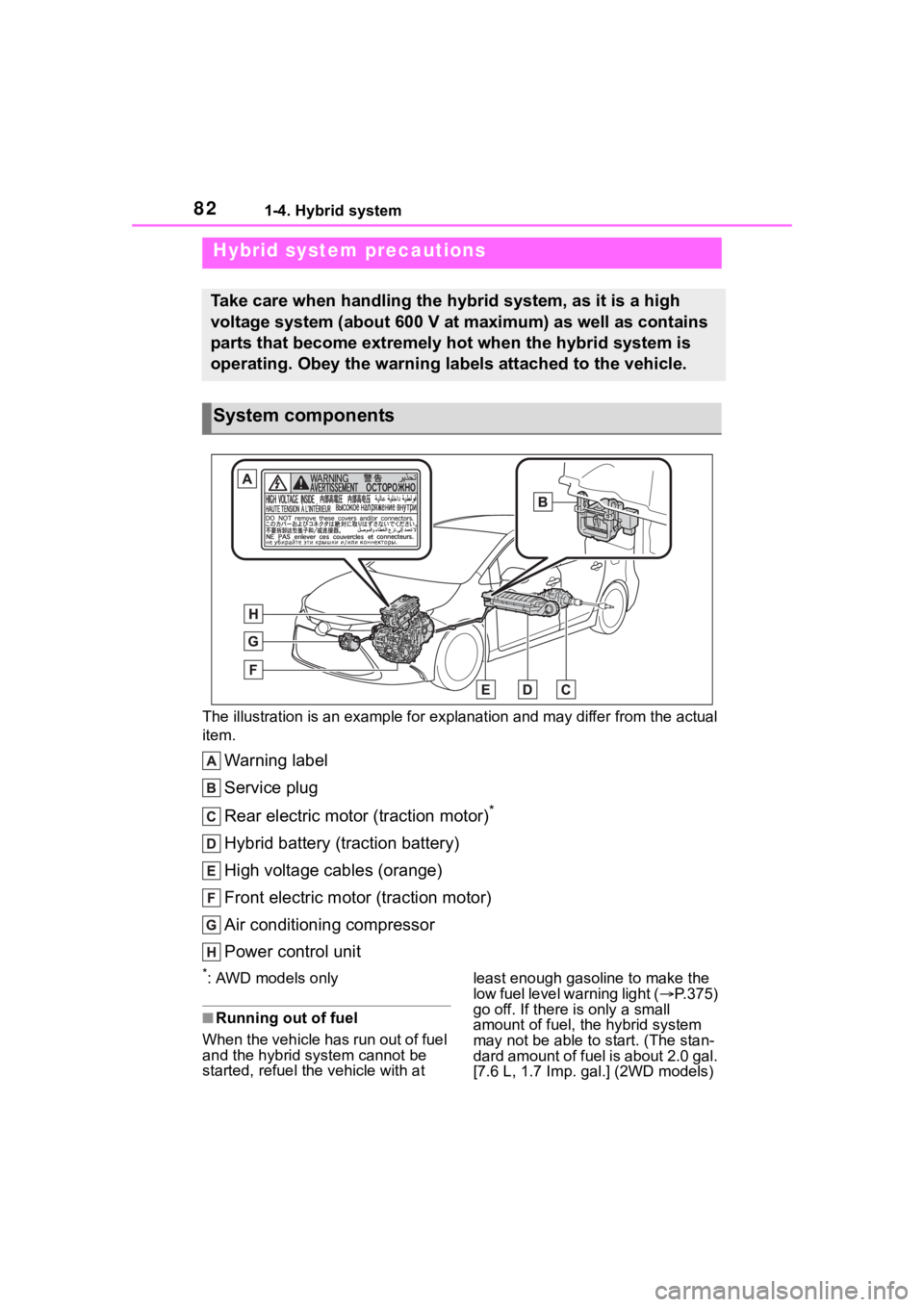
The illustration is an example for explanation and may differ from the actual
item.
Warning label
Service plug
Rear electric motor (traction motor)
*
Hybrid battery (traction battery)
High voltage cables (orange)
Front electric motor (traction motor)
Air conditioning compressor
Power control unit
*: AWD models only
■Running out of fuel
When the vehicle has run out of fuel
and the hybrid system cannot be
started, refuel th e vehicle with at least enough gasoline to make the
low fuel level warning light (
P.375)
go off. If there is only a small
amount of fuel, the hybrid system
may not be able to start. (The stan-
dard amount of fuel is about 2.0 gal.
[7.6 L, 1.7 I mp. gal.] (2WD models)
Hybrid system precautions
Take care when handling the hybrid system, as it is a high
voltage system (about 600 V at maximum) as well as contains
parts that become extremely hot when the hybrid system is
operating. Obey the warning labels attached to the vehicle.
System components
Page 83 of 496
![TOYOTA COROLLA HYBRID 2023 Owners Manual 831-4. Hybrid system
1
For safety and security
or 1.6 gal. [6.0 L, 1.3 Imp. gal.]
(AWD models) when the vehicle is
on a level surface. This value may
vary when the vehicle is on a slope.
Add extra](/manual-img/14/59253/w960_59253-82.png "TOYOTA COROLLA HYBRID 2023 Owners Manual 831-4. Hybrid system
1
For safety and security
or 1.6 gal. [6.0 L, 1.3 Imp. gal.]
(AWD models) when the vehicle is
on a level surface. This value may
vary when the vehicle is on a slope.
Add extra")
831-4. Hybrid system
1
For safety and security
or 1.6 gal. [6.0 L, 1.3 Imp. gal.]
(AWD models) when the vehicle is
on a level surface. This value may
vary when the vehicle is on a slope.
Add extra fuel when the vehicle is
inclined.)
■Electromagnetic waves
●High voltage parts and cables on
hybrid vehicles incorporate elec-
tromagnetic shielding, and there-
fore emit approximately the same
amount of electromagnetic waves
as conventional gasoline pow-
ered vehicles or home electronic
appliances.
●Your vehicle may cause sound
interference in some third
party-produced radio parts.
■Hybrid battery (traction battery)
The hybrid battery (traction battery)
has a limited service life. The lifes-
pan of the hybrid battery (traction
battery) can change in accordance
with driving style and driving condi-
tions.
■Starting the hybrid system in an
extremely cold environment
When the hybrid battery (traction
battery) is extremely cold (below
approximately -22°F [-30°C]) under
the influence of t he outside tem-
perature, it may no t be possible to
start the hybrid system. In this case,
try to start the hybrid system again
after the temperature of the hybrid
battery increases due to the outside
temperature increasing, etc.
WARNING
■High voltage precautions
This vehicle has high voltage DC
and AC systems as well as a
12-volt system. DC and AC high
voltage is very dangerous and
can cause severe burns and elec-
tric shock that may result in death
or serious injury.
●Never touch, disassemble,
remove or replace the high volt-
age parts, cables or their con-
nectors.
●The hybrid system will become
hot after starting as the system
uses high voltage. Be careful of
both the high voltage and the
high temperature, and always
obey the warning labels
attached to the vehicle.
●Never try to open the service
plug access hole located under
the right side o f the rear seat.
The service plug is used only
when the vehicle is serviced
and is subject to high voltage.
■Road accident cautions
Observe the following precautions
to reduce the risk of death or seri-
ous injury:
●Pull your vehicle off the road,
apply the parking brake, shift
the shift lever to P, and turn the
hybrid system off.
●Do not touch the high voltage
parts, cables and connectors.
●If electric wires are exposed
inside or outside your vehicle,
an electric shock may occur.
Never touch exposed electric
wires.
Page 95 of 496
952-1. Instrument cluster
2
Vehicle status information and indicators
*1: These lights come on when the power switch is turned to ON to
indicate that a system check is
being performed. They will turn
off after the hybrid system is on,
or after a few seconds. There
may be a malfunction in a sys-
tem if the lights do not come on,
or turn off. Have the vehicle inspected by your Toyota dealer.
*2: This light comes on when the
system is turned off.
*3: This light illuminates on the out-side rear view mirrors.
*4: This light illuminates on the multi-information display.
*5: When the outside temperature is approximately 37°F (3°C) or
lower, this indicator will flash for
approximately 10 seconds, then
stay on.
*6: This light illuminates on the cen-ter panel.
*7: This light illuminates on the over-head console.
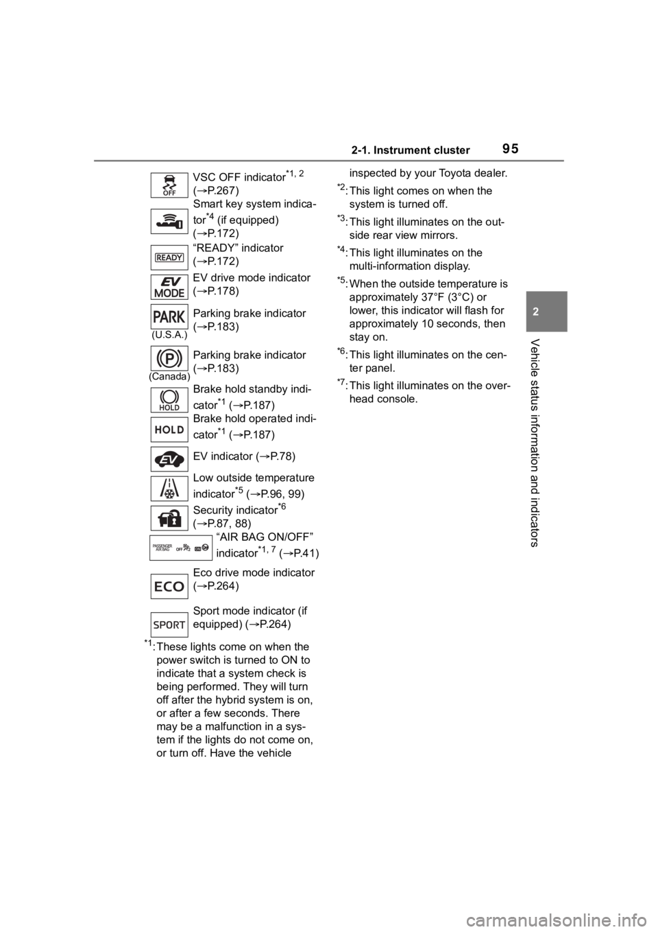
VSC OFF indicator
*1, 2
( P.267)
Smart key system indica-
tor
*4 (if equipped)
( P.172)
“READY” indicator
( P.172)
EV drive mode indicator
( P.178)
(U.S.A.)
Parking brake indicator
( P.183)
(Canada)
Parking brake indicator
( P.183)
Brake hold standby indi-
cator
*1 ( P.187)
Brake hold operated indi-
cator
*1 ( P.187)
EV indicator ( P. 7 8 )
Low outside temperature
indicator
*5 ( P.96, 99)
Security indicator
*6
( P.87, 88)
“AIR BAG ON/OFF”
indicator
*1, 7 ( P. 4 1 )
Eco drive mode indicator
( P.264)
Sport mode indicator (if
equipped) ( P.264)
Page 108 of 496

1082-1. Instrument cluster
• Average vehicle speed: Displays the average vehi cle speed since
the display was reset
*
*
: To reset, display the desired item
and press and hold the
meter control switch.
■AWD operation status dis-
play (AWD models)
The illustration used is intended as
an example, and may differ from the
image that is actually displayed on
the multi-information display.
Torque distribution display
Displays the drive status of each
wheel in 6 steps from 0 to 5.
■Meter display settings that
can be changed
Language
Select to change the language dis-
played.
Units
Select to change t he units of mea-
sure displayed.
EV indicator
Select to enable/disable the EV
indicator.
Select to change the displayed con-
tent of the following:
• Hybrid system indicator
Select to displa y/not display the
Eco Accelerator Guidance.
( P.104)
• Fuel economy display
Select to change the average fuel
consumption display between after
start/after reset. ( P.104)
Select to displa y/not display the
audio system linked display.
Select to change the displayed con-
tent of the following:
• Display contents
Select to displa y/not display the
energy monitor. (P. 1 1 6 )
• Drive information type
Select to change the drive informa-
tion type display between after
start/after reset.
• Drive information items
Select to set the first and second
items of the drive information dis-
play to any of the following: aver-
age vehicle
speed/distance/elapsed time.
Pop-up display
Select to enable/disable pop-up
displays for each relevant system.
Multi-information display off
Select to turn the multi-information
display off.
To turn the multi-information display
Settings display
Page 114 of 496

1142-1. Instrument cluster
reset*
• Elapsed time: Displays the elapsed time since the display
was reset
*
• Average vehicle speed: Displays the average vehi cle speed since
the display was reset
*
*
: To reset, display the desired item
and press and hold the
meter control switch.
■AWD operation status dis-
play (AWD models)
The illustration used is intended as
an example, and may differ from the
image that is actually displayed on
the multi-information display.
Torque distribution display
Displays the drive status of each
wheel in 6 steps from 0 to 5.
■Meter display settings that
can be changed
Language
Select to change the language dis-
played.
Units
Select to change t he units of mea- sure displayed.
Meter Type
Select to change the meter type.
Dial Type
Select to change the display of the
speedometer, tachometer or Hybrid
System Indicator.
EV indicator
Select to enable/disable the EV
indicator.
• Fuel economy display
Select to change the average fuel
consumption display to any of the
following: trip average/total aver-
age/tank average. ( P. 1 1 0 )
• Hybrid system display
Select to displa y/not display the
zone of Eco acceleration of the Eco
Accelerator Guidance. (P. 1 1 1 )
Select to displa y/not display the
audio system linked display.
Select to change the displayed con-
tent of the following:
• Display contents
Select to displa y/not display the
energy monitor. (P. 1 1 6 )
• Drive information type
Select to change the drive informa-
tion type display between trip infor-
mation/total information.
• Drive information items
Select to set the first and second
items of the drive information dis-
Settings display
Page 122 of 496
1223-1. Key information
3-1.Key information
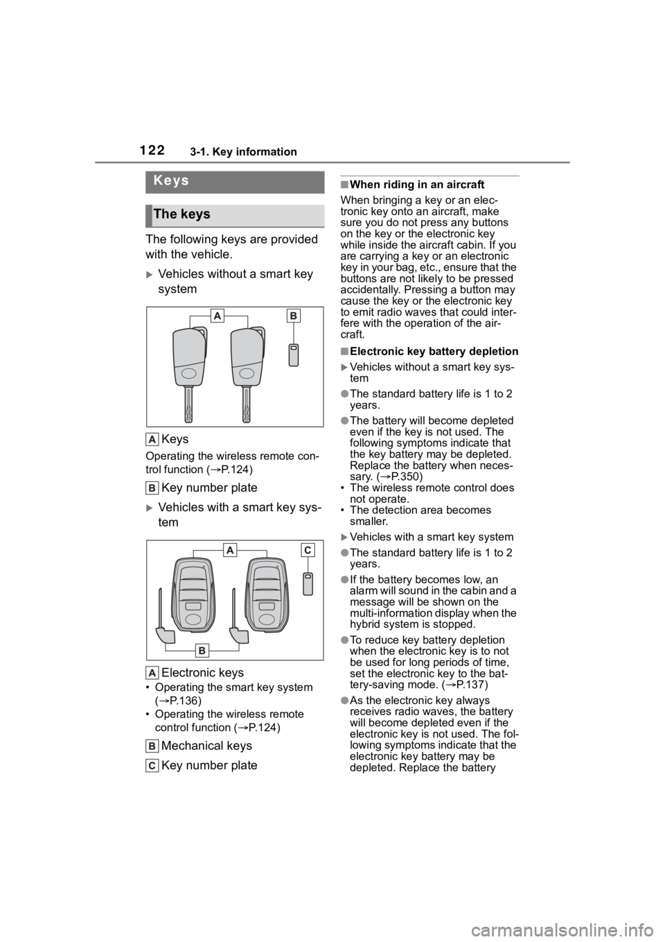
The following keys are provided
with the vehicle.
Vehicles without a smart key
systemKeys
Operating the wireless remote con-
trol function ( P.124)
Key number plate
Vehicles with a smart key sys-
tem
Electronic keys
• Operating the smart key system ( P.136)
• Operating the wireless remote control function ( P.124)
Mechanical keys
Key number plate
■When riding in an aircraft
When bringing a key or an elec-
tronic key onto an aircraft, make
sure you do not press any buttons
on the key or the electronic key
while inside the airc raft cabin. If you
are carrying a key or an electronic
key in your bag, etc., ensure that the
buttons are not likely to be pressed
accidentally. Pressing a button may
cause the key or the electronic key
to emit radio waves that could inter-
fere with the operation of the air-
craft.
■Electronic key battery depletion
Vehicles without a smart key sys-
tem
●The standard battery life is 1 to 2
years.
●The battery will be come depleted
even if the key is not used. The
following symptoms indicate that
the key battery may be depleted.
Replace the battery when neces-
sary. ( P.350)
• The wireless remote control does
not operate.
• The detection area becomes smaller.
Vehicles with a smart key system
●The standard battery life is 1 to 2
years.
●If the battery bec omes low, an
alarm will sound in the cabin and a
message will be shown on the
multi-information display when the
hybrid system is stopped.
●To reduce key battery depletion
when the electronic key is to not
be used for long periods of time,
set the electronic key to the bat-
tery-saving mode. ( P.137)
●As the electronic key always
receives radio waves, the battery
will become depleted even if the
electronic key is not used. The fol-
lowing symptoms indicate that the
electronic key battery may be
depleted. Replace the battery
Keys
The keys