Page 92 of 496
922-1. Instrument cluster
2-1.Instrument cluster
For the purpose of explanation, the following illustrations display all
warning lights and indicators illuminated.
4.2-inch display
7-inch display
War ning lights and indicators
The warning lights and indicators on the instrument cluster,
center panel, overhead console and outside rear view mirrors
inform the driver of the status of the vehicle’s various sys-
tems.
Warning lights and indicators displayed on the instru-
ment cluster
Page 93 of 496
932-1. Instrument cluster
2
Vehicle status information and indicators
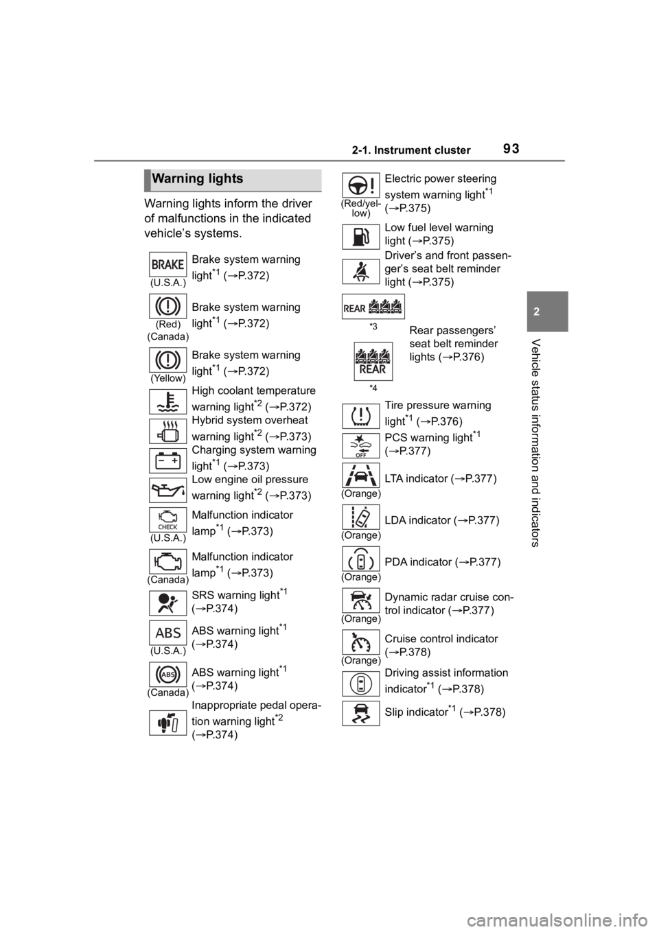
Warning lights inform the driver
of malfunctions in the indicated
vehicle’s systems.
Warning lights
(U.S.A.)
Brake system warning
light
*1 ( P.372)
(Red)
(Canada)
Brake system warning
light
*1 ( P.372)
(Yellow)
Brake system warning
light
*1 ( P.372)
High coolant temperature
warning light
*2 ( P.372)
Hybrid system overheat
warning light
*2 ( P.373)
Charging system warning
light
*1 ( P.373)
Low engine oil pressure
warning light
*2 ( P.373)
(U.S.A.)
Malfunction indicator
lamp
*1 ( P.373)
(Canada)
Malfunction indicator
lamp
*1 ( P.373)
SRS warning light
*1
( P.374)
(U.S.A.)
ABS warning light*1
( P.374)
(Canada)
ABS warning light*1
( P.374)
Inappropriate pedal opera-
tion warning light
*2
( P.374)
(Red/yel-
low)
Electric power steering
system warning light
*1
( P.375)
Low fuel leve l warning
light ( P.375)
Driver’s and front passen-
ger’s seat belt reminder
light ( P.375)
*3Rear passengers’
seat belt reminder
lights ( P.376)
*4
Tire pressure warning
light
*1 ( P.376)
PCS warning light
*1
( P.377)
(Orange)
LTA indicator ( P.377)
(Orange)
LDA indicator ( P.377)
(Orange)
PDA indicator ( P.377)
(Orange)
Dynamic radar cruise con-
trol indicator ( P.377)
(Orange)
Cruise control indicator
( P.378)
Driving assist information
indicator
*1 ( P.378)
Slip indicator
*1 ( P.378)
Page 94 of 496
942-1. Instrument cluster
*1: These lights come on when the power switch is turned to ON to
indicate that a system check is
being performed. They will turn
off after the hybrid system is on,
or after a few seconds. There
may be a malfunction in a sys-
tem if the lights do not come on,
or turn off. Have the vehicle
inspected by your Toyota dealer.
*2: This light illuminates on the multi-information display.
*3: 4.2-inch display.
*4: 7-inch display.
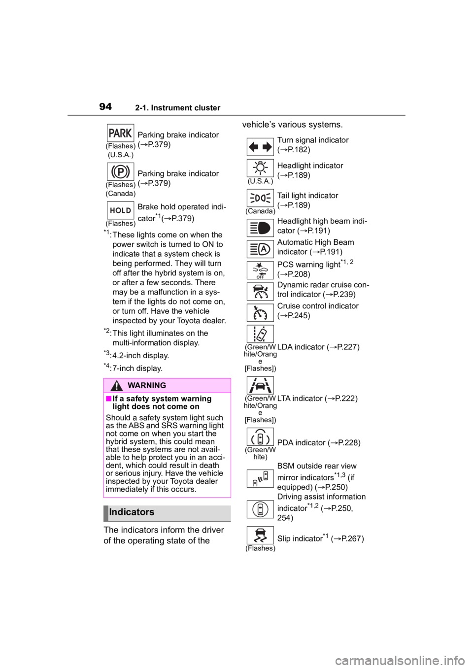
The indicators inform the driver
of the operating state of the vehicle’s various systems.
(Flashes)
(U.S.A.)
Parking brake indicator
( P.379)
(Flashes)
(Canada)
Parking brake indicator
( P.379)
(Flashes)
Brake hold operated indi-
cator
*1( P.379)
WARNING
■If a safety system warning
light does not come on
Should a safety system light such
as the ABS and SRS warning light
not come on when you start the
hybrid system, this could mean
that these systems are not avail-
able to help protect you in an acci-
dent, which could result in death
or serious injury. Have the vehicle
inspected by your Toyota dealer
immediately if this occurs.
Indicators
Turn signal indicator
( P.182)
(U.S.A.)
Headlight indicator
( P.189)
(Canada)
Tail light indicator
( P.189)
Headlight high beam indi-
cator ( P.191)
Automatic High Beam
indicator ( P.191)
PCS warning light
*1, 2
( P.208)
Dynamic radar cruise con-
trol indicator ( P.239)
Cruise control indicator
( P.245)
(Green/W
hite/Orang e
[Flashes])LDA indicator ( P.227)
(Green/W
hite/Orang e
[Flashes])LTA indicator ( P.222)
(Green/W
hite)PDA indicator ( P.228)
BSM outside rear view
mirror indicators
*1,3 (if
equipped) ( P.250)
Driving assist information
indicator
*1,2 ( P.250,
254)
(Flashes)
Slip indicator*1 ( P.267)
Page 101 of 496
1012-1. Instrument cluster
2
Vehicle status information and indicators
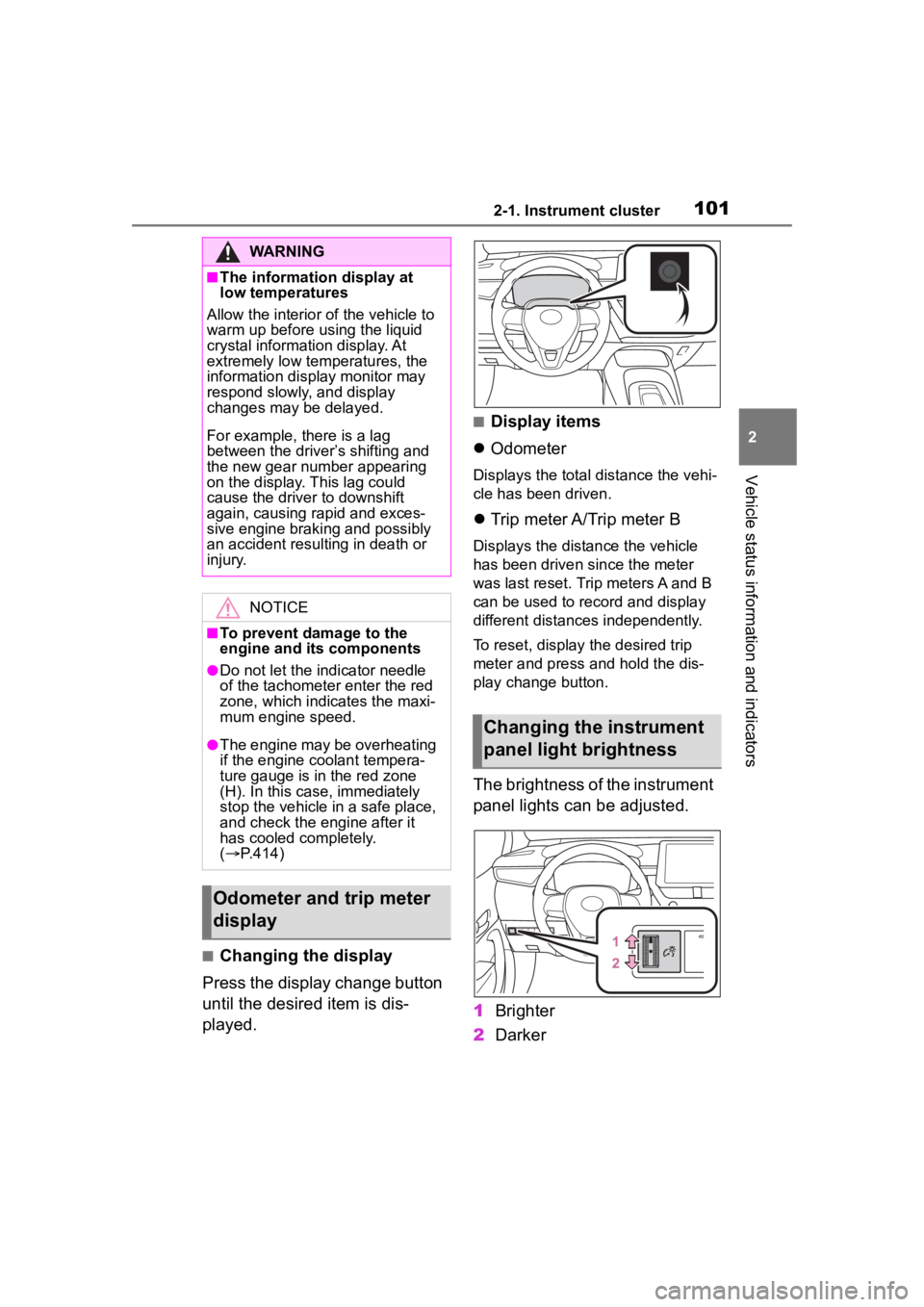
■Changing the display
Press the display change button
until the desired item is dis-
played.
■Display items
Odometer
Displays the total distance the vehi-
cle has been driven.
Trip meter A/Trip meter B
Displays the distance the vehicle
has been driven since the meter
was last reset. Trip meters A and B
can be used to record and display
different distances independently.
To reset, display the desired trip
meter and press and hold the dis-
play change button.
The brightness of the instrument
panel lights can be adjusted.
1 Brighter
2 Darker
WARNING
■The information display at
low temperatures
Allow the interior of the vehicle to
warm up before u sing the liquid
crystal informat ion display. At
extremely low temperatures, the
information display monitor may
respond slowly, and display
changes may be delayed.
For example, there is a lag
between the driver’s shifting and
the new gear number appearing
on the display. This lag could
cause the driver to downshift
again, causing rapid and exces-
sive engine braking and possibly
an accident resulting in death or
injury.
NOTICE
■To prevent damage to the
engine and its components
●Do not let the i ndicator needle
of the tachomete r enter the red
zone, which indicates the maxi-
mum engine speed.
●The engine may be overheating
if the engine coolant tempera-
ture gauge is in the red zone
(H). In this case, immediately
stop the vehicle in a safe place,
and check the engine after it
has cooled completely.
( P.414)
Odometer and trip meter
display
Changing the instrument
panel light brightness
Page 102 of 496
1022-1. Instrument cluster
■Instrument panel light bright-
ness adjustment
The brightness of the instrument
panel lights can be adjusted sepa-
rately for when the tail lights are on
and off.
■The clocks can be adjusted
on the audio system
screen.
Refer to “MULTIMEDIA
OWNER’S MANUAL”.
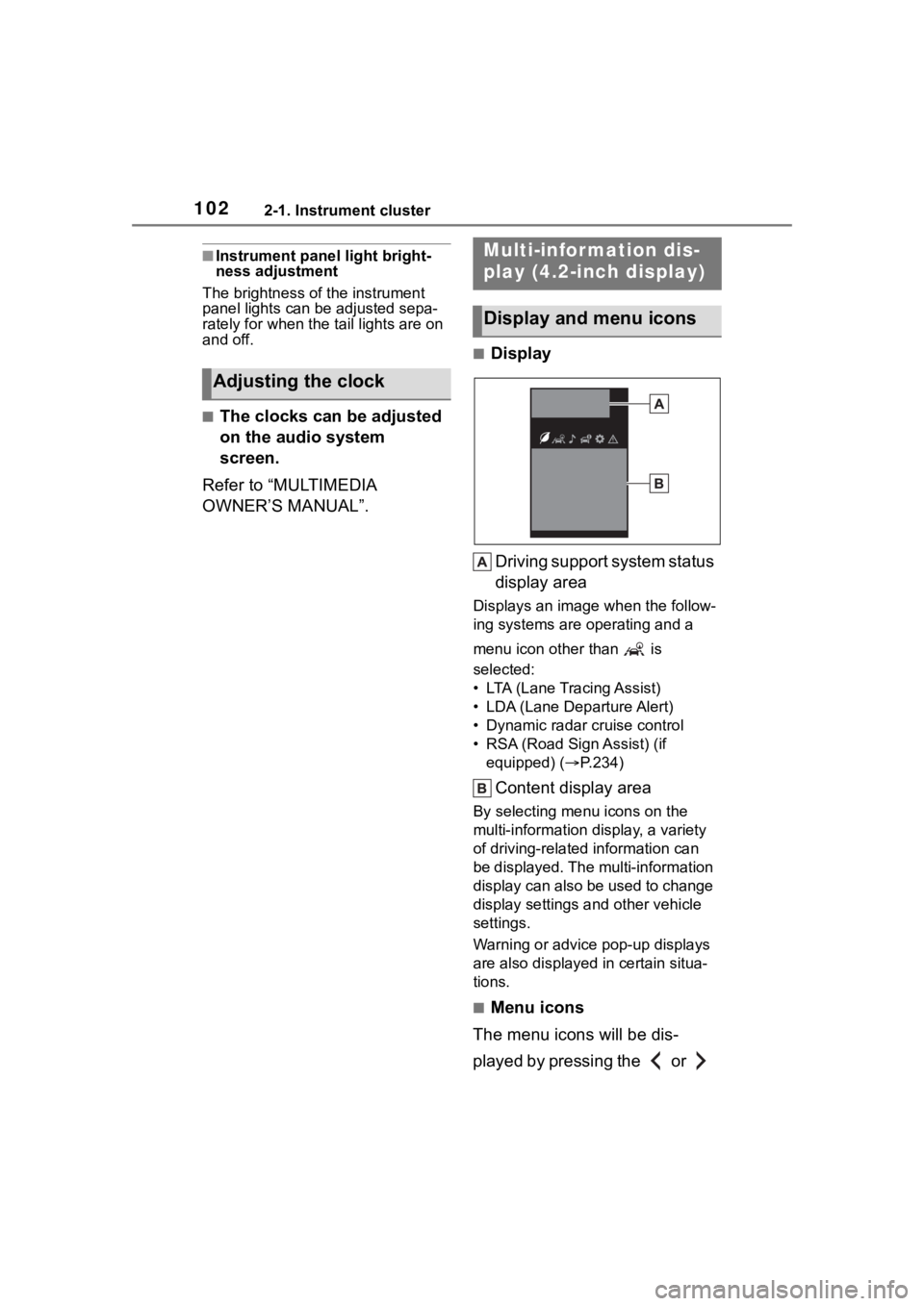
■Display
Driving support system status
display area
Displays an image when the follow-
ing systems are operating and a
menu icon other than is
selected:
• LTA (Lane Tracing Assist)
• LDA (Lane Departure Alert)
• Dynamic radar cruise control
• RSA (Road Sign Assist) (if equipped) ( P.234)
Content display area
By selecting menu icons on the
multi-information di splay, a variety
of driving-related information can
be displayed. The multi-information
display can also be used to change
display settings and other vehicle
settings.
Warning or advice pop-up displays
are also displayed in certain situa-
tions.
■Menu icons
The menu icons will be dis-
played by pressing the or
Adjusting the clock
Multi-infor mation dis-
play (4.2-inch display)
Display and menu icons
Page 147 of 496
1473-4. Adjusting the steering wheel and mirrors
3
Before driving
The height of the rear view mir-
ror can be adjusted to suit your
driving posture.
Adjust the height of the rear
view mirror by moving it up and
down.
Reflected light from the head-
lights of vehicles behind can be
reduced by operating the lever.Normal position
Anti-glare position
Inside rear view mirror
The rear view mirror’s posi-
tion can be adjusted to
enable sufficient confirma-
tion of the rear view.
Adjusting the height of
rear view mirror
WARNING
■Caution while driving
Do not adjust the position of the
mirror while driving.
Doing so may lead to mishandling
of the vehicle and cause an acci-
dent, resulting in death or serious
injury.
Anti-glare function
Page 182 of 496
1824-2. Driving procedures
P.264
1Right turn
2 Lane change to the right
(move the lever partway and
release it)
The right hand s ignals will flash 3
times.
3 Lane change to the left
(move the lever partway and
release it)
The left hand signals will flash 3
times.
4Left turn
■Turn signals can be operated
when
The power switch is in ON.
■If the indicator flashes faster
than usual
Check that a light bulb in the front or
rear turn signal lights has not
WARNING
■To prevent an accident when
releasing the shift lock
Before pressing the shift lock
override button, make sure to set
the parking brake and depress the
brake pedal.
If the accelerator pedal is acci-
dentally depressed instead of the
brake pedal when the shift lock
override button is pressed and the
shift lever is shifted out of P, the
vehicle may suddenly start, possi-
bly leading to an accident result-
ing in death or serious injury.
Selecting the driving
mode
Tur n signal lever
Operating instructions
Page 191 of 496
1914-3. Operating the lights and wipers
4
Driving
■Customization
Some functions can be customized.
( P.442)
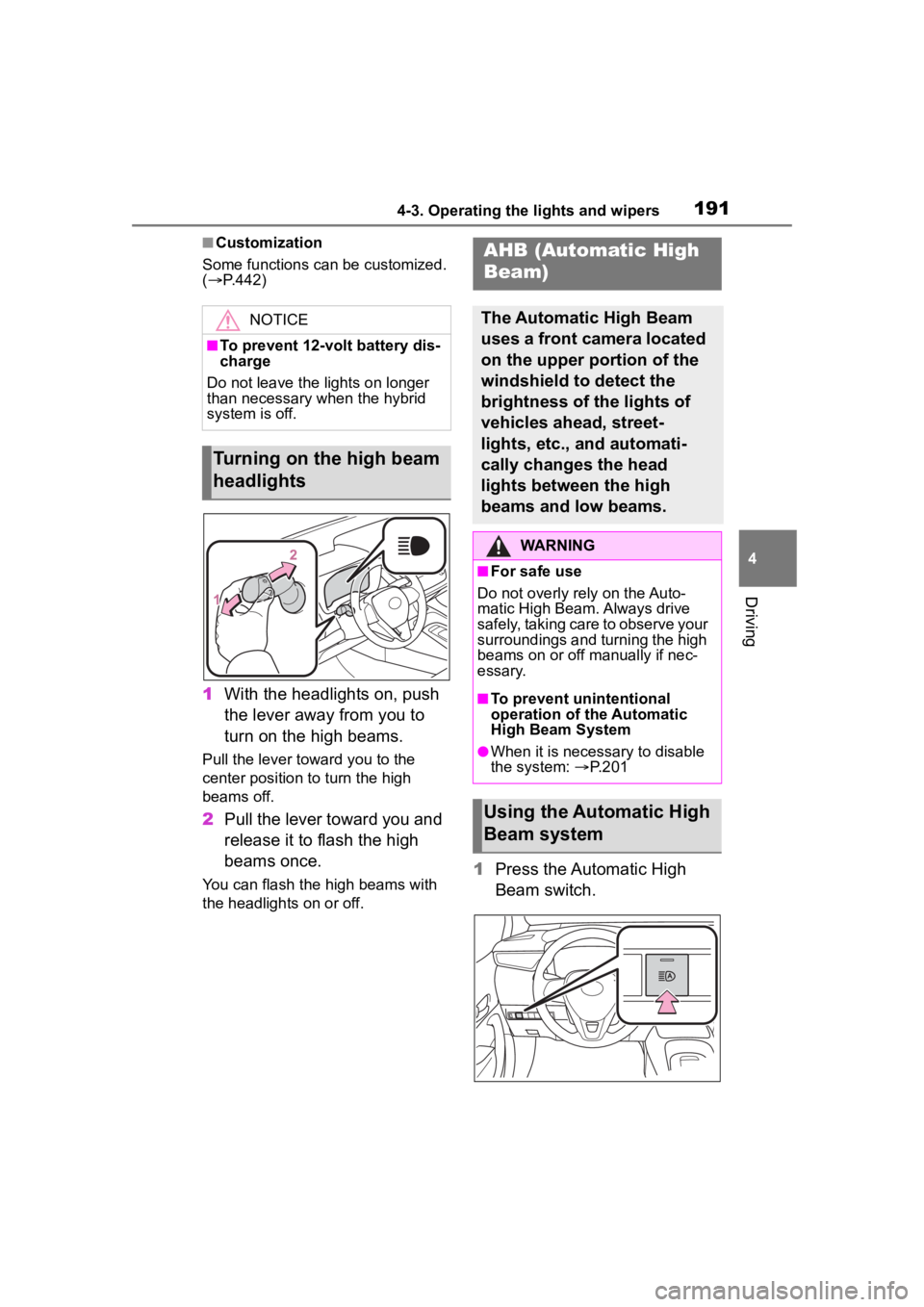
1 With the headlights on, push
the lever away from you to
turn on the high beams.
Pull the lever toward you to the
center position to turn the high
beams off.
2Pull the lever toward you and
release it to flash the high
beams once.
You can flash the high beams with
the headlights on or off.1Press the Automatic High
Beam switch.
NOTICE
■To prevent 12-volt battery dis-
charge
Do not leave the lights on longer
than necessary when the hybrid
system is off.
Turning on the high beam
headlights
AHB (Automatic High
Beam)
The Automatic High Beam
uses a front camera located
on the upper portion of the
windshield to detect the
brightness of the lights of
vehicles ahead, street-
lights, etc., and automati-
cally changes the head
lights between the high
beams and low beams.
WARNING
■For safe use
Do not overly rely on the Auto-
matic High Beam. Always drive
safely, taking care to observe your
surroundings and turning the high
beams on or off manually if nec-
essary.
■To prevent unintentional
operation of the Automatic
High Beam System
●When it is necessary to disable
the system: P.201
Using the Automatic High
Beam system