2023 TOYOTA COROLLA HYBRID height
[x] Cancel search: heightPage 147 of 496
1473-4. Adjusting the steering wheel and mirrors
3
Before driving
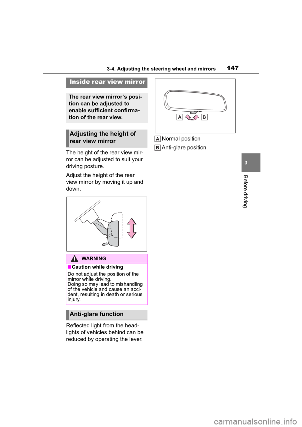
The height of the rear view mir-
ror can be adjusted to suit your
driving posture.
Adjust the height of the rear
view mirror by moving it up and
down.
Reflected light from the head-
lights of vehicles behind can be
reduced by operating the lever.Normal position
Anti-glare position
Inside rear view mirror
The rear view mirror’s posi-
tion can be adjusted to
enable sufficient confirma-
tion of the rear view.
Adjusting the height of
rear view mirror
WARNING
■Caution while driving
Do not adjust the position of the
mirror while driving.
Doing so may lead to mishandling
of the vehicle and cause an acci-
dent, resulting in death or serious
injury.
Anti-glare function
Page 205 of 496

2054-5. Using the driving support systems
4
Driving
■Situations in which the sensors
may not operate properly
●When the height or inclination of
the vehicle has been changed due
to modifications
●When the windshield is dirty,
fogged up, cracked or damaged
●When the ambient temperature is
high or low
●When mud, water, snow, dead
insects, foreign matter, etc., is
attached to the front of the sensor
●When in inclement weather such
as heavy rain, fog, snow, or a
sandstorm
●When water, snow, dust, etc. is
thrown up in front of the vehicle, or
when driving through mist or
smoke
●When the headlig hts are not illu-
minated while driving in the dark,
such as at night o r when in a tun-
nel
●When the lens of a headlight is
dirty and illumination is weak
●When the headlights are mis-
aligned
●When a headlight is malfunction-
ing
●When the headlights of another
vehicle, sunlight, or reflected light
shines directly into the front cam-
era
●When the brightness of the sur-
rounding area changes suddenly
●When driving near a TV tower,
broadcasting station, electric
power plant, radar equipped vehi-
cles, etc., or other location where
strong radio waves or electrical
noise may be present
●When a wiper blade is blocking
the front camera
●When in a location or near objects
which strongly reflect radio waves,
such as the following:
• Tunnels
• Truss bridges
• Gravel roads
• Rutted, snow-covered roads
• Walls
• Large trucks
• Manhole covers
• Guardrail
• Metal plates
●When near a step or protrusion
●When a detectable vehicle is nar-
row, such as a small mobility vehi-
cle
●When a detectable vehicle has a
small front or rear end, such as an
unloaded truck
●When a detectable vehicle has a
low front or rear end, such as a
low bed trailer
●When a detectable vehicle has
extremely high ground clearance
WARNING
■Front camera installation area
on the windshield
If the system determines that the
windshield may be fogged up, it
will automatically operate the
heater to defog the part of the
windshield around the front cam-
era. When cleaning, etc., be care-
ful not to touch the area around
the front camera until the wind-
shield has cooled sufficiently, as
touching it may cause burns.
Page 253 of 496

2534-5. Using the driving support systems
4
Driving
tional when all of the following con-
ditions are met:
●The power switch is in ON.
●The Blind Spot Monitor is on.
●The shift lever is in a position
other than R.
●The vehicle speed is approxi-
mately 7 mph (10 km/h) or more.
■The Blind Spot Monitor will
detect a vehicle when
The Blind Spot Mon itor will detect a
vehicle present in the detection area
in the followin g situations:
●A vehicle in an adjacent lane over-
takes your vehicle.
●You overtake a vehicle in an adja-
cent lane slowly.
●Another vehicle enters the detec-
tion area when it changes lanes.
■Situations in which the blind
spot monitor cannot detect
vehicles.
The blind spot monitor cannot
detect the following vehicles and
other objects:
●Small motorcycles, bicycles,
pedestrians, etc.*
●Vehicles traveling in the opposite
direction
●Guardrails, walls, signs, parked
vehicles and similar stationary
objects
*
●Following vehicles that are in the
same lane*
●Vehicles traveling 2 lanes away
from your vehicle*
●Vehicles which are being over-
taken rapidly by your vehicle*
*
: Depending on the conditions, detection of a vehicle and/or
object may occur.
■Conditions under which the
System may not function cor-
rectly
●The Blind Spot Monitor may not
detect vehicles corr ectly in the fol-
lowing situations:
• When the sensor is misaligned due to a strong impact to the sen-
sor or its surrounding area
• When mud, snow, ice, a sticker, etc. is covering the sensor or sur-
rounding area on the rear bumper
• When driving on a road surface that is wet with standing water
during bad weather, such as
heavy rain, snow, or fog
• When multiple vehicles are
approaching with only a small gap
between each vehicle
• When the distance between your
vehicle and a following vehicle is
short
• When there is a significant differ-
ence in speed between your vehi-
cle and the vehicle that enters the
detection area
• When the difference in speed between your vehicle and another
vehicle is changing
• When a vehicle enters a detection area traveling at about the same
speed as your vehicle
• As your vehicle starts from a stop, a vehicle remains in the detection
area
• When driving up and down con- secutive steep inclines, such as
hills, dips in the road, etc.
• When driving on r oads with sharp
bends, consecutive curves, or
uneven surfaces
• When vehicle lanes are wide, or when driving on the edge of a
lane, and the vehicle in an adja-
cent lane is far away from your
vehicle
• When an accessory (such as a bicycle carrier) is installed to the
rear of the vehicle
• When there is a significant differ- ence in height between your vehi-
cle and the vehicle that enters the
detection area
• Immediately after the Blind Spot
Page 258 of 496
2584-5. Using the driving support systems
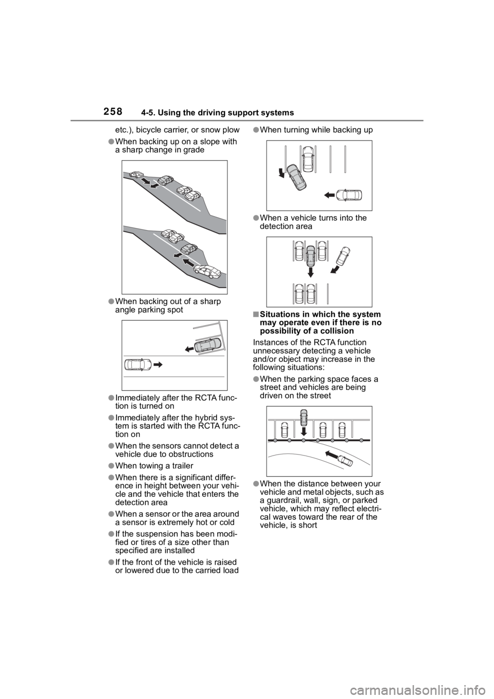
etc.), bicycle carrier, or snow plow
●When backing up on a slope with
a sharp change in grade
●When backing out of a sharp
angle parking spot
●Immediately after the RCTA func-
tion is turned on
●Immediately after the hybrid sys-
tem is started with the RCTA func-
tion on
●When the sensors cannot detect a
vehicle due to obstructions
●When towing a trailer
●When there is a significant differ-
ence in height between your vehi-
cle and the vehicle that enters the
detection area
●When a sensor or the area around
a sensor is extremely hot or cold
●If the suspension has been modi-
fied or tires of a size other than
specified are installed
●If the front of the vehicle is raised
or lowered due to the carried load
●When turning while backing up
●When a vehicle tu rns into the
detection area
■Situations in which the system
may operate even if there is no
possibility of a collision
Instances of the RCTA function
unnecessary detec ting a vehicle
and/or object may increase in the
following situations:
●When the parking space faces a
street and vehicles are being
driven on the street
●When the distance between your
vehicle and metal objects, such as
a guardrail, wall, sign, or parked
vehicle, which may reflect electri-
cal waves toward the rear of the
vehicle, is short
Page 365 of 496
3657-1. Essential information
7
When trouble arises
outside water level exceeds
half the height of the door, the
door cannot be opened from
the inside due to water pres-
sure.
■Water level exceeds the floor
When the water level exceeds the
floor and time has passed, the elec-
trical equipment will get damaged,
the power windows will not operate,
the engine and motor stop, and the
vehicle may not be able to get mov-
ing.
■Using an emergency escape
hammer*
Laminated glass is used in the wind-
shield on this vehicle.
Laminated glass cannot be shat-
tered with an emergency hammer
*.
Tempered glass is used in the win-
dows on this vehicle.
*: Contact your Toyota dealer or
aftermarket accessory manufac-
turer for further information about
an emergency hammer.
WARNING
■Caution while driving
Do not drive on roads where the
roads may be submerged or the
water may be rising. Otherwise
the vehicle may be damaged and
cannot move, as well as become
flooded and set a drift, which may
lead to death.
Page 400 of 496
4007-2. Steps to take in an emergency
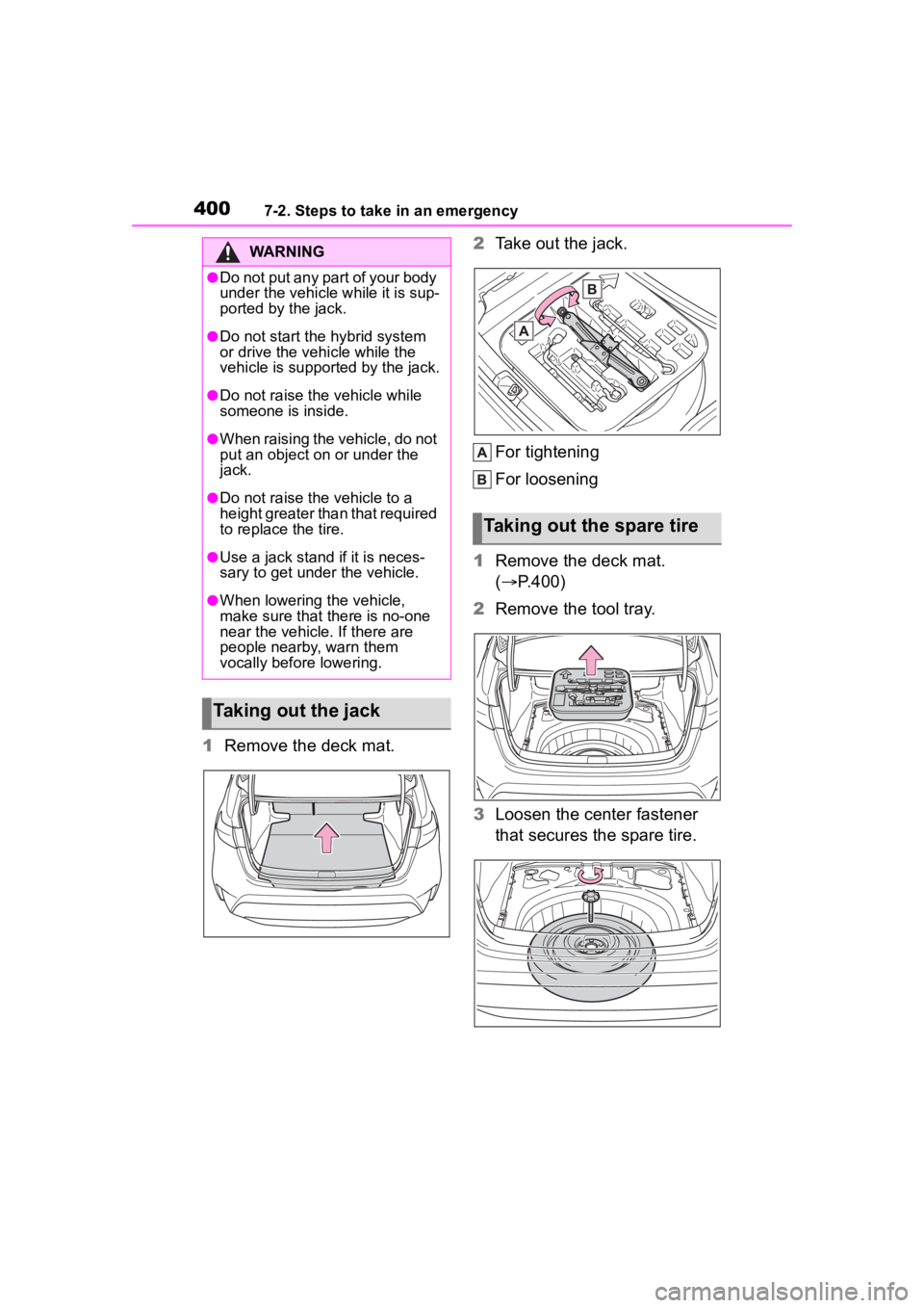
1Remove the deck mat. 2
Take out the jack.
For tightening
For loosening
1 Remove the deck mat.
( P.400)
2 Remove the tool tray.
3 Loosen the center fastener
that secures the spare tire.
WARNING
●Do not put any part of your body
under the vehicle while it is sup-
ported by the jack.
●Do not start the hybrid system
or drive the vehicle while the
vehicle is suppor ted by the jack.
●Do not raise the vehicle while
someone is inside.
●When raising the vehicle, do not
put an object on or under the
jack.
●Do not raise the vehicle to a
height greater than that required
to replace the tire.
●Use a jack stand if it is neces-
sary to get under the vehicle.
●When lowering the vehicle,
make sure that there is no-one
near the vehicle. If there are
people nearby, warn them
vocally before lowering.
Taking out the jack
Taking out the spare tire
Page 420 of 496
4208-1. Specifications
8-1.Specifications
*1: Unladen vehicles
*2: Vehicles without 225/40R18 tires
*3: Vehicles with 225/40R18 tires
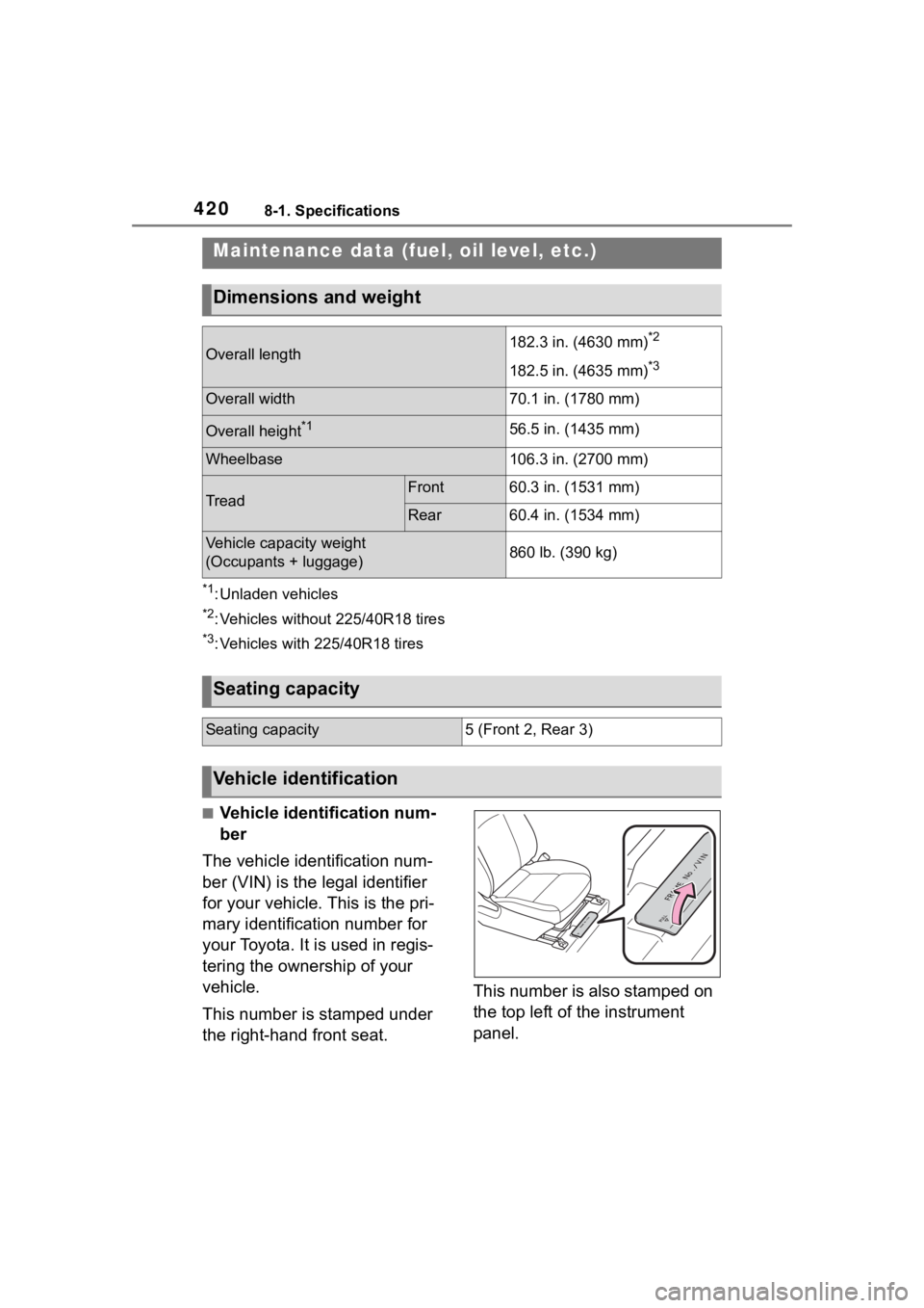
■Vehicle identification num-
ber
The vehicle identification num-
ber (VIN) is the legal identifier
for your vehicle. This is the pri-
mary identification number for
your Toyota. It is used in regis-
tering the ownership of your
vehicle.
This number is stamped under
the right-hand front seat. This number is also stamped on
the top left of the instrument
panel.
Maintenance data (fuel, oil level, etc.)
Dimensions and weight
Overall length182.3 in. (4630 mm)*2
182.5 in. (4635 mm)*3
Overall width70.1 in. (1780 mm)
Overall height*156.5 in. (1435 mm)
Wheelbase106.3 in. (2700 mm)
TreadFront60.3 in. (1531 mm)
Rear60.4 in. (1534 mm)
Vehicle capacity weight
(Occupants + luggage)860 lb. (390 kg)
Seating capacity
Seating capacity5 (Front 2, Rear 3)
Vehicle identification
Page 433 of 496
4338-1. Specifications
8
Vehicle specifications
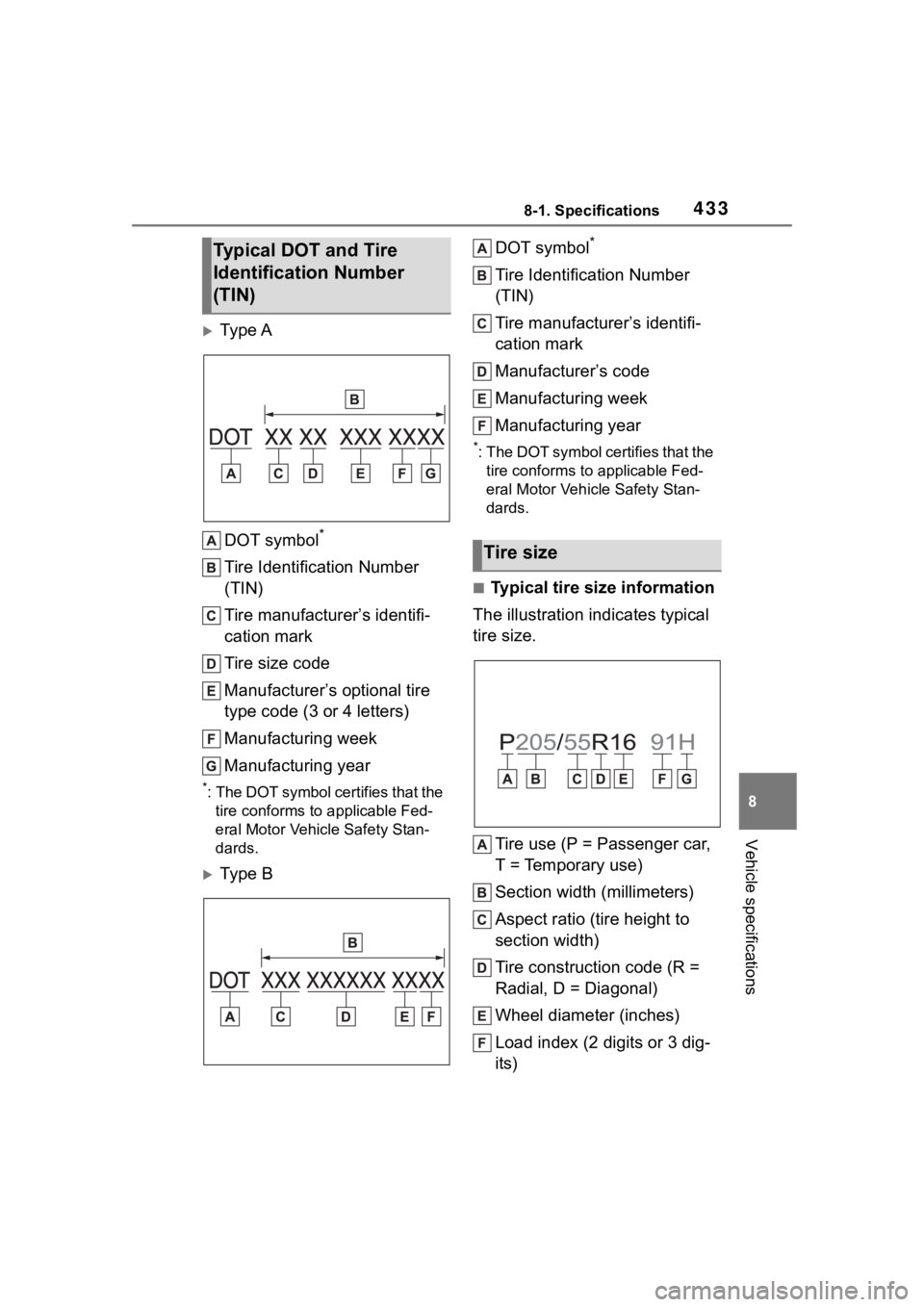
Ty p e ADOT symbol
*
Tire Identification Number
(TIN)
Tire manufacturer’s identifi-
cation mark
Tire size code
Manufacturer’s optional tire
type code (3 or 4 letters)
Manufacturing week
Manufacturing year
*: The DOT symbol certifies that the tire conforms to applicable Fed-
eral Motor Vehicle Safety Stan-
dards.
Ty p e B DOT symbol
*
Tire Identification Number
(TIN)
Tire manufacturer’s identifi-
cation mark
Manufacturer’s code
Manufacturing week
Manufacturing year
*: The DOT symbol ce
rtifies that the
tire conforms to applicable Fed-
eral Motor Vehicle Safety Stan-
dards.
■Typical tire size information
The illustration indicates typical
tire size.
Tire use (P = Passenger car,
T = Temporary use)
Section width (millimeters)
Aspect ratio (tire height to
section width)
Tire construction code (R =
Radial, D = Diagonal)
Wheel diameter (inches)
Load index (2 digits or 3 dig-
its)
Typical DOT and Tire
Identification Number
(TIN)
Tire size