2023 TOYOTA COROLLA CROSS tires
[x] Cancel search: tiresPage 408 of 500

4087-2. Steps to take in an emergency
When replacing tires on a vehi-
cle with wheel lock nuts, use the
following procedures to remove
and install the wheel lock nuts.
The wheel lock key is stored in
the tray inside the luggage com-
partment. Always return the
wheel lock key to its original
position after use, so that it does
not get lost. (P.406)
■Removal
For ease of removal, the wheel
lock nut should always be the
first one loosened.
1 Place the wheel lock key on
top of the wheel lock nut,
turning until the wheel lock
key and wheel lock nut pat-
terns engage.
2 Place the wheel nut wrench
on the wheel lock key, and
while applying pressure on
the wheel lock key, loosen
the wheel lock nut.
■Installation
For ease of installation, the
wheel lock nut should always be
the last one tightened.
1 By hand, install a wheel lock
nut on the wheel to be
installed.
2 Place the wheel lock key on
top of the wheel lock nut,
turning until the wheel lock
key and wheel lock nut pat-
terns engage.
3 Place the wheel nut wrench
on the wheel lock key, and
while applying pressure on
the wheel lock key, tighten
the wheel lock nut to the rec-
ommended torque.
WARNING
●Do not raise the vehicle while
someone is inside.
●When raising the vehicle, do not
put an object on or under the
jack.
●Do not raise the vehicle to a
height greater than that required
to replace the tire.
●Use a jack stand if it is neces-
sary to get under the vehicle.
●When lowering the vehicle,
make sure that there is no-one
near the vehicle. If there are
people nearby, warn them
vocally before lowering.
Wheel lock nut (if
equipped)
NOTICE
■When using a wheel lock key
(if equipped)
Do not use an impact wrench.
Using an impact wrench may
cause permanent damage to
wheel lock nut and wheel lock
key. If in doubt about wheel lock
application, contact your Toyota
dealer.
Page 410 of 500
4107-2. Steps to take in an emergency
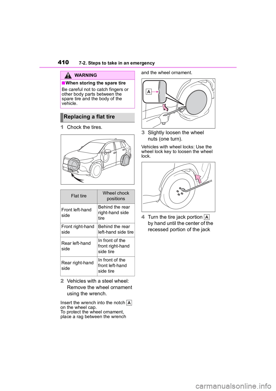
1Chock the tires.
2 Vehicles with a steel wheel:
Remove the wheel ornament
using the wrench.
Insert the wrench into the notch
on the wheel cap.
To protect the wheel ornament,
place a rag between the wrench and the wheel ornament.
3
Slightly loosen the wheel
nuts (one turn).
Vehicles with wheel locks: Use the
wheel lock key to loosen the wheel
lock.
4 Turn the tire jack portion
by hand until the center of the
recessed portion of the jack
WARNING
■When storing the spare tire
Be careful not to catch fingers or
other body parts between the
spare tire and the body of the
vehicle.
Replacing a flat tire
Flat tireWheel chock positions
Front left-hand
sideBehind the rear
right-hand side
tire
Front right-hand
sideBehind the rear
left-hand side tire
Rear left-hand
sideIn front of the
front right-hand
side tire
Rear right-hand
sideIn front of the
front left-hand
side tire
Page 413 of 500
4137-2. Steps to take in an emergency
7
When trouble arises
3Lower the vehicle.
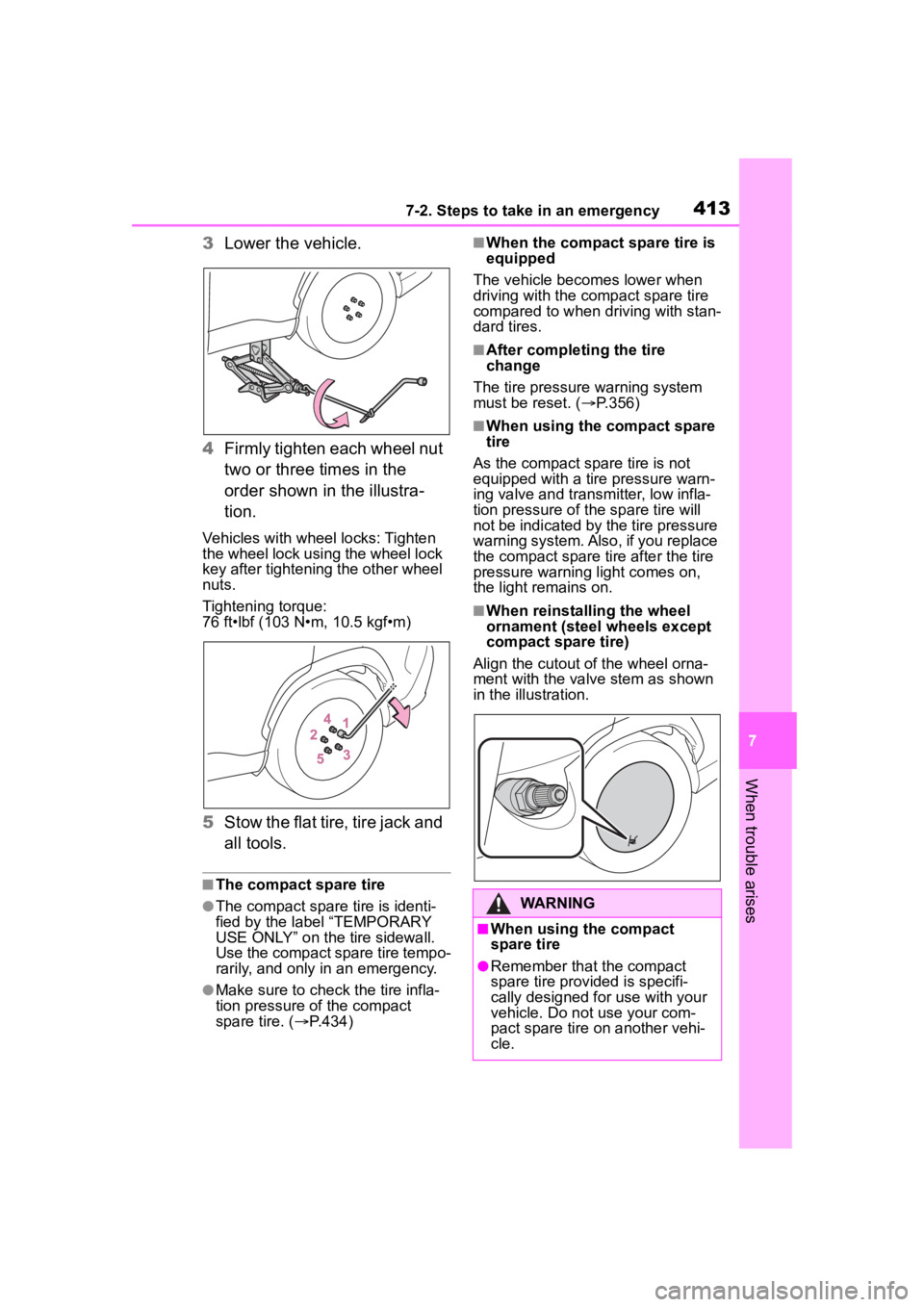
4 Firmly tighten each wheel nut
two or three times in the
order shown in the illustra-
tion.
Vehicles with wheel locks: Tighten
the wheel lock using the wheel lock
key after tightening the other wheel
nuts.
Tightening torque:
76 ft•lbf (103 N•m, 10.5 kgf•m)
5Stow the flat tire, tire jack and
all tools.
■The compact spare tire
●The compact spare tire is identi-
fied by the label “TEMPORARY
USE ONLY” on the tire sidewall.
Use the compact spare tire tempo-
rarily, and only in an emergency.
●Make sure to check the tire infla-
tion pressure of the compact
spare tire. ( P.434)
■When the compact spare tire is
equipped
The vehicle becomes lower when
driving with the compact spare tire
compared to when driving with stan-
dard tires.
■After completing the tire
change
The tire pressure warning system
must be reset. ( P.356)
■When using the compact spare
tire
As the compact spare tire is not
equipped with a tire pressure warn-
ing valve and transm itter, low infla-
tion pressure of the spare tire will
not be indicated by the tire pressure
warning system. Also , if you replace
the compact spare ti re after the tire
pressure warning light comes on,
the light remains on.
■When reinstalling the wheel
ornament (steel wheels except
compact spare tire)
Align the cutout of the wheel orna-
ment with the valve stem as shown
in the illustration.
WARNING
■When using the compact
spare tire
●Remember that the compact
spare tire provided is specifi-
cally designed for use with your
vehicle. Do not use your com-
pact spare tire on another vehi-
cle.
Page 414 of 500

4147-2. Steps to take in an emergency
WARNING
●Do not use more than one com-
pact spare tires simultaneously.
●Replace the compact spare tire
with a standard tire as soon as
possible.
●Avoid sudden acceleration,
abrupt steering, sudden brak-
ing and shifting operations that
cause sudden engine braking.
■When the compact spare tire
is attached
The vehicle speed may not be
correctly detecte d, and the follow-
ing systems may not operate cor-
rectly:
• ABS & Brake assist
• VSC
• TRAC
• Automatic High Beam
• AFS (Adaptive Front-lighting System) (if equipped)
• Dynamic radar cruise control with full-speed range
• EPS
• PCS (Pre-Collision System)
• LTA (Lane Tracing Assist)
• Tire pressure warning system
• Intuitive parking assist (if equipped)
• PKSB (Parking Support Brake) (if equipped)
• BSM (Blind Spot Monitor) (if equipped)
• RCTA (Rear Cross Traffic Alert) function (if equipped)
• SEA (Safe Exit Assist) (if equipped)
• Rear view monitor system
Also, not only c an the following
system not be utilized fully, but it
may even negatively affect the
drive-train components:
• AWD system (AWD models)
■Speed limit when using the
compact spare tire
Do not drive at speeds in excess
of 50 mph (80 km /h) when a com-
pact spare tire is installed on the
vehicle.
The compact spare tire is not
designed for driving at high
speeds. Failure to observe this
precaution may lead to an acci-
dent causing death or serious
injury.
■After using the tools and jack
Before driving, ma ke sure all the
tools and jack are securely in
place in their storage location to
reduce the possibility of personal
injury during a collision or sudden
braking.
NOTICE
■Be careful when driving over
bumps with the compact
spare tire installed on the
vehicle.
The vehicle becomes lower when
driving with the compact spare tire
compared to when driving with
standard tires. Be careful when
driving over uneven road sur-
faces.
■Driving with tire chains and
the compact spare tire
Do not fit tire chains to the com-
pact spare tire. Tire chains may
damage the vehicle body and
adversely affect d riving perfor-
mance.
Page 415 of 500
4157-2. Steps to take in an emergency
7
When trouble arises
One of the following may be the
cause of the problem:
There may not be sufficient
fuel in the vehicle’s tank.
Refuel the vehicle.
The engine may be flooded.
Try to restart the engine again
following correct starting pro-
cedures. ( P.162, 163)
There may be a malfunction
in the engine immobilizer sys-
tem. ( P.68)
One of the following may be the
cause of the problem:
The battery may be dis-
charged. ( P.419)
NOTICE
■When replacing the tires
When removing or fitting the
wheels, tires or the tire pressure
warning valve and transmitter,
contact your Toyota dealer as the
tire pressure warning valve and
transmitter may be damaged if not
handled correctly.
■To avoid damage to the tire
pressure warning valves and
transmitters
When a tire is repaired with liquid
sealants, the tire pressure warn-
ing valve and transmitter may not
operate properly. If a liquid seal-
ant is used, contact your Toyota
dealer or other qualified service
shop as soon as possible. Make
sure to replace the tire pressure
warning valve and transmitter
when replacing the tire.
If the engine will not
star t
If the engine will not start
even though correct starting
procedures are being fol-
lowed ( P.162, 163), con-
sider each of the following
points:
The engine will not start
even though the starter
motor operates normally.
The starter motor turns
over slowly, the interior
lights and headlights are
dim, or the horn does not
sound or sounds at a low
volume.
Page 425 of 500
4257-2. Steps to take in an emergency
7
When trouble arises
1Stop the engine. Set the
parking brake and shift the
shift lever to P.
Do not press the shift lever button
after shifting the shit position to P.
2Remove the mud, snow or
sand from around the front
wheels.
3 Place wood, stones or some
other material under the front
wheels to help provide trac-
tion.
4 Restart the engine.
5 Shift the shift lever to D or R
and release the parking
brake. Then, while exercising
caution, depress the acceler-
ator pedal.
■When it is difficult to free the
vehicle
Press the switch to turn off
TRAC.
WARNING
●If steam is seen coming from
under the hood, do not open the
hood until the steam has sub-
sided. The engine compart-
ment may be very hot.
●Keep hands and clothing (espe-
cially a tie, a scarf or a muffler)
away from the fan and belts.
Failure to do so m ay cause the
hands or clothing to be caught,
resulting in serious injury.
●Do not loosen the coolant reser-
voir cap while the engine and
radiator are hot.
High temperature steam or
coolant could spray out.
NOTICE
■When adding engine coolant
Add coolant slowly after the
engine has cooled down suffi-
ciently. Adding cool coolant to a
hot engine too quickly can cause
damage to the engine.
■To prevent damage to the
cooling system
Observe the following precau-
tions:
●Avoid contaminating the coolant
with foreign matter (such as
sand or dust etc.).
●Do not use any coolant additive.
If the vehicle becomes
stuck
Carry out the following pro-
cedures if the tires spin or
the vehicle becomes stuck
in mud, dirt or snow:
Recovering procedure
Page 428 of 500

4288-1. Specifications
8-1.Specifications
*1: Unladen vehicles
*2: Vehicles with 215/65R17 tires
*3: Vehicles with 225/55R18 tires
Maintenance data (fuel, oil level, etc.)
Dimensions and weight
Overall length175.6 in. (4460 mm)
Overall width71.9 in. (1825 mm)
Overall height*164.8 in. (1645 mm)
Wheelbase103.9 in. (2640 mm)
Tread*1
Front
2WD models
61.6 in. (1565 mm)
*2
61.2 in. (1555 mm)*3
AWD models
61.7 in. (1566 mm)
*2
61.3 in. (1556 mm)*3
Rear
2WD models
62.2 in. (1580 mm)
*2
61.8 in. (1569 mm)*3
AWD models
61.6 in. (1564 mm)
*2
61.2 in. (1554 mm)*3
Vehicle capacity weight
(Occupants + luggage)940 lb. (425 kg)
Trailer Weight Rating
(Trailer weight + cargo weight)1500 lb. (680 kg)
Seating capacity
Seating capacity5 (Front 2, Rear 3)
Page 434 of 500
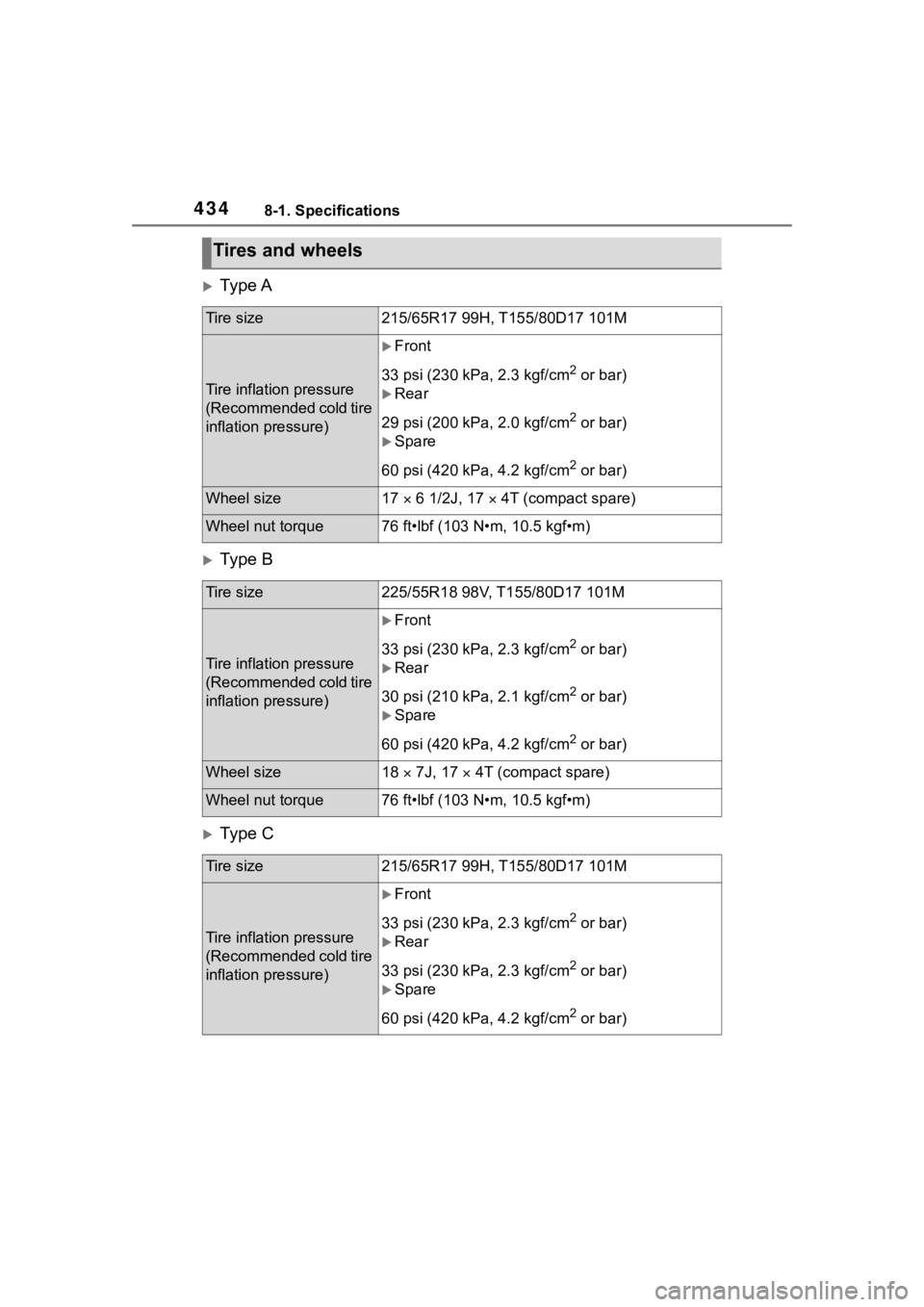
4348-1. Specifications
Ty p e A
Ty p e B
Ty p e C
Tires and wheels
Tire size215/65R17 99H, T155/80D17 101M
Tire inflation pressure
(Recommended cold tire
inflation pressure)
Front
33 psi (230 kPa, 2.3 kgf/cm
2 or bar)
Rear
29 psi (200 kPa, 2.0 kgf/cm
2 or bar)
Spare
60 psi (420 kPa, 4.2 kgf/cm
2 or bar)
Wheel size17 6 1/2J, 17 4T (compact spare)
Wheel nut torque76 ft•lbf (103 N•m, 10.5 kgf•m)
Tire size225/55R18 98V, T155/80D17 101M
Tire inflation pressure
(Recommended cold tire
inflation pressure)
Front
33 psi (230 kPa, 2.3 kgf/cm
2 or bar)
Rear
30 psi (210 kPa, 2.1 kgf/cm
2 or bar)
Spare
60 psi (420 kPa, 4.2 kgf/cm
2 or bar)
Wheel size18 7J, 17 4T (compact spare)
Wheel nut torque76 ft•lbf (103 N•m, 10.5 kgf•m)
Tire size215/65R17 99H, T155/80D17 101M
Tire inflation pressure
(Recommended cold tire
inflation pressure)
Front
33 psi (230 kPa, 2.3 kgf/cm
2 or bar)
Rear
33 psi (230 kPa, 2.3 kgf/cm
2 or bar)
Spare
60 psi (420 kPa, 4.2 kgf/cm
2 or bar)