Page 34 of 500
341-1. For safe use
WARNING
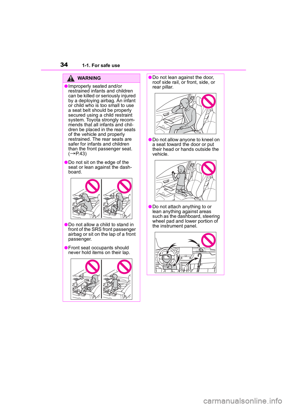
●Improperly seated and/or
restrained infants and children
can be killed or seriously injured
by a deploying airbag. An infant
or child who is too small to use
a seat belt should be properly
secured using a child restraint
system. Toyota strongly recom-
mends that all infants and chil-
dren be placed in the rear seats
of the vehicle and properly
restrained. The rear seats are
safer for infants and children
than the front passenger seat.
(
P. 4 3 )
●Do not sit on the edge of the
seat or lean against the dash-
board.
●Do not allow a child to stand in
front of the SRS front passenger
airbag or sit on the lap of a front
passenger.
●Front seat occupants should
never hold items on their lap.
●Do not lean against the door,
roof side rail, or front, side, or
rear pillar.
●Do not allow anyone to kneel on
a seat toward the door or put
their head or han ds outside the
vehicle.
●Do not attach anything to or
lean anything against areas
such as the dashboard, steering
wheel pad and lower portion of
the instrument panel.
Page 35 of 500
351-1. For safe use
1
For safety and security
WARNING
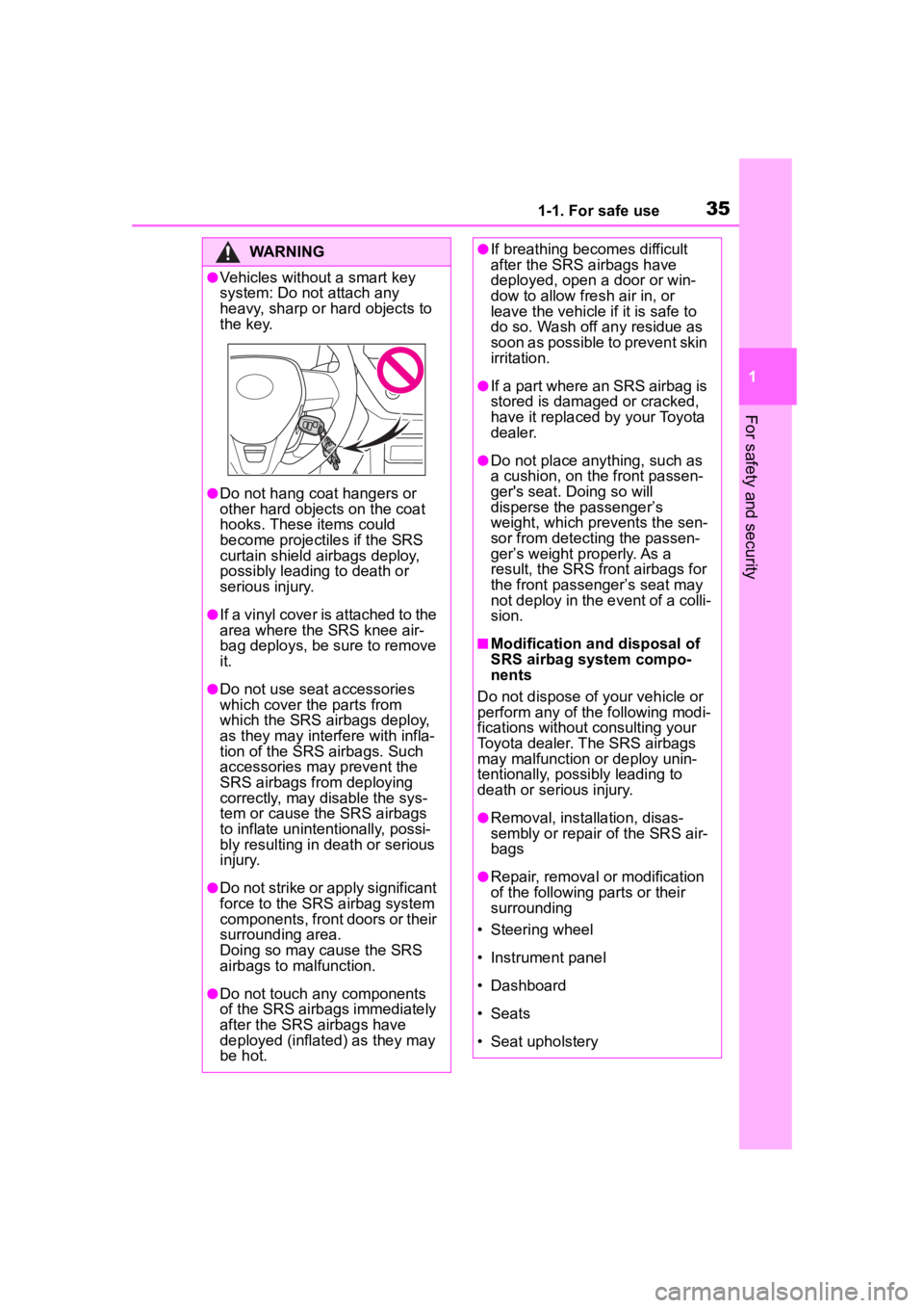
●Vehicles without a smart key
system: Do not attach any
heavy, sharp or hard objects to
the key.
●Do not hang coat hangers or
other hard objects on the coat
hooks. These items could
become projectiles if the SRS
curtain shield airbags deploy,
possibly leading to death or
serious injury.
●If a vinyl cover is attached to the
area where the SRS knee air-
bag deploys, be sure to remove
it.
●Do not use seat accessories
which cover the parts from
which the SRS airbags deploy,
as they may interfere with infla-
tion of the SRS airbags. Such
accessories may prevent the
SRS airbags from deploying
correctly, may disable the sys-
tem or cause the SRS airbags
to inflate unintentionally, possi-
bly resulting in death or serious
injury.
●Do not strike or apply significant
force to the SRS airbag system
components, front doors or their
surrounding area.
Doing so may cause the SRS
airbags to malfunction.
●Do not touch any components
of the SRS airbags immediately
after the SRS airbags have
deployed (inflated) as they may
be hot.
●If breathing becomes difficult
after the SRS airbags have
deployed, open a door or win-
dow to allow fresh air in, or
leave the vehicle if it is safe to
do so. Wash off any residue as
soon as possible to prevent skin
irritation.
●If a part where an SRS airbag is
stored is damaged or cracked,
have it replaced by your Toyota
dealer.
●Do not place anything, such as
a cushion, on the front passen-
ger's seat. Doing so will
disperse the passenger’s
weight, which prevents the sen-
sor from detecting the passen-
ger’s weight properly. As a
result, the SRS front airbags for
the front passenger’s seat may
not deploy in the event of a colli-
sion.
■Modification and disposal of
SRS airbag system compo-
nents
Do not dispose of your vehicle or
perform any of the following modi-
fications without consulting your
Toyota dealer. The SRS airbags
may malfunction or deploy unin-
tentionally, possi bly leading to
death or serious injury.
●Removal, installation, disas-
sembly or repair of the SRS air-
bags
●Repair, removal or modification
of the following parts or their
surrounding
• Steering wheel
• Instrument panel
• Dashboard
• Seats
• Seat upholstery
Page 86 of 500

862-1. Instrument cluster
type and drive information items
were selected in . (P.86)
After start
• Distance: Displays the distance
driven since e ngine start
• Elapsed time: Displays the elapsed time since engine start
• Average vehicle speed: Displays the average vehi cle speed since
engine start
After reset
• Distance: Displays the distance
driven since the display was
reset
*
• Elapsed time: Displays the elapsed time since the display
was reset
*
• Average vehicle speed: Displays the average vehi cle speed since
the display was reset
*
*
: To reset, display the desired item
and press and hold the
meter control switch.
■Tire pressure
P. 3 5 3
■AWD operation status dis-
play (if equipped)
The illustration used is intended as an example, and may differ from the
image that is actually displayed on
the multi-information display.
Torque distribution display
Displays the drive status of each
wheel in 6 steps from 0 to 5.
■Meter display settings that
can be changed
Language
Select to change the language dis-
played.
Units
Select to change the units of mea-
sure displayed.
Eco Driving Indicator Light
Select to enable/disable the Eco
Driving Indi cator Light.
Fuel economy display
Select to change the average fuel
consumption display between after
start/after reset. ( P. 8 3 )
Select to displa y/not display the
audio system linked display.
Select to change the displayed con-
tent of the following:
• Drive information type
Select to change the drive informa-
tion type display between after
start/after reset.
• Drive information items
Settings display
Page 92 of 500
922-1. Instrument cluster
Route guidance to destination
Compass display (head-
ing-up display)
Select to enable selection of an
audio source or track on the
meter using the meter control
switches.
This menu icon can be set to be
displayed/not displayed in .
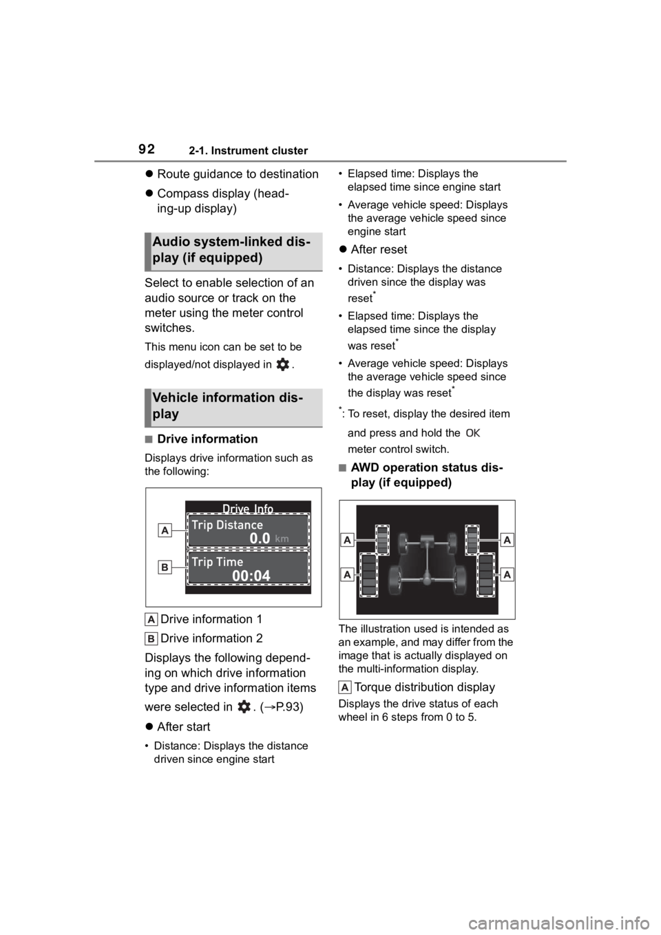
■Drive information
Displays drive information such as
the following:
Drive information 1
Drive information 2
Displays the following depend-
ing on which drive information
type and drive information items
were selected in . ( P.93)
After start
• Distance: Displays the distance
driven since e ngine start • Elapsed time: Displays the
elapsed time since engine start
• Average vehicle speed: Displays the average vehicle speed since
engine start
After reset
• Distance: Displays the distance
driven since the display was
reset
*
• Elapsed time: Displays the elapsed time since the display
was reset
*
• Average vehicle speed: Displays the average vehicle speed since
the display was reset
*
*
: To reset, display the desired item and press and hold the
meter control switch.
■AWD operation status dis-
play (if equipped)
The illustration used is intended as
an example, and may differ from the
image that is actually displayed on
the multi-information display.
Torque distribution display
Displays the drive status of each
wheel in 6 steps from 0 to 5.
Audio system-linked dis-
play (if equipped)
Vehicle information dis-
play
Page 97 of 500
97
3
3
Before driving
Before driving
.3-1. Key informationKeys ............................... 98
3-2. Opening, closing and locking the doors
Side doors ................... 103
Back door .................... 108
Smart key system ....... 118
3-3. Adjusting the seats Front seats .................. 123
Rear seats................... 124
Head restraints............ 126
3-4. Adjusting the steering wheel and mirrors
Steering wheel ............ 128
Inside rear view mirror .................................. 129
Outside rear view mirrors .................................. 130
3-5. Opening and closing the windows
Power windows ........... 132
Moon roof .................... 135
3-6. Favorite settings My Settings ................. 138
Page 128 of 500
1283-4. Adjusting the steering wheel and mirrors
3-4.Adjusting the steering wheel and mirrors
1Hold the steering wheel and
push the lever down.
2 Adjust to the ideal position by
moving the steering wheel
horizontally and vertically.
After adjustment, pull the lever up
to secure the steering wheel.
To sound the horn, press on or
close to the mark.
Steering wheel
Adjustment procedure
WARNING
■Caution while driving
Do not adjust the steering wheel
while driving.
Doing so may cause the driver to
mishandle the vehicle and cause
an accident, resul ting in death or
serious injury.
■After adjusting the steering
wheel
Make sure that the steering wheel
is securely locked.
Otherwise, the steering wheel
may move suddenly, possibly
causing an accident, and resulting
in death or serious injury. Also,
the horn may not sound if the
steering wheel is not securely
locked.
Horn
Page 129 of 500
1293-4. Adjusting the steering wheel and mirrors
3
Before driving
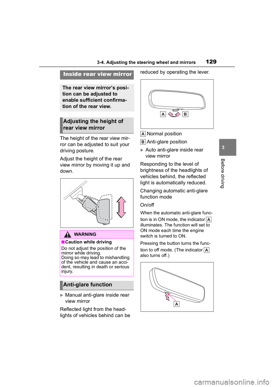
The height of the rear view mir-
ror can be adjusted to suit your
driving posture.
Adjust the height of the rear
view mirror by moving it up and
down.
Manual anti-glare inside rear
view mirror
Reflected light from the head-
lights of vehicles behind can be reduced by operating the lever.
Normal position
Anti-glare position
Auto anti-glare inside rear
view mirror
Responding to the level of
brightness of the headlights of
vehicles behind, the reflected
light is automatically reduced.
Changing automatic anti-glare
function mode
On/off
When the automatic anti-glare func-
tion is in ON mode, the indicator
illuminates. The func tion will set to
ON mode each time the engine
switch is turned to ON.
Pressing the button turns the func-
tion to off mode. (The indicator
also turns off.)
Inside rear view mirror
The rear view mirror’s posi-
tion can be adjusted to
enable sufficient confirma-
tion of the rear view.
Adjusting the height of
rear view mirror
WARNING
■Caution while driving
Do not adjust the position of the
mirror while driving.
Doing so may lead to mishandling
of the vehicle and cause an acci-
dent, resulting in death or serious
injury.
Anti-glare function
Page 130 of 500
1303-4. Adjusting the steering wheel and mirrors
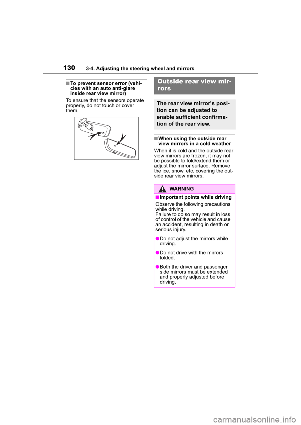
■To prevent sensor error (vehi-
cles with an auto anti-glare
inside rear view mirror)
To ensure that the sensors operate
properly, do not touch or cover
them.
■When using the outside rear
view mirrors in a cold weather
When it is cold and the outside rear
view mirrors are fr ozen, it may not
be possible to fold/extend them or
adjust the mirror s urface. Remove
the ice, snow, etc. covering the out-
side rear view mirrors.
Outside rear view mir-
rors
The rear view mirror’s posi-
tion can be adjusted to
enable sufficient confirma-
tion of the rear view.
WARNING
■Important points while driving
Observe the following precautions
while driving.
Failure to do so may result in loss
of control of the vehicle and cause
an accident, resulting in death or
serious injury.
●Do not adjust the mirrors while
driving.
●Do not drive wit h the mirrors
folded.
●Both the driver and passenger
side mirrors must be extended
and properly adjusted before
driving.