2023 TOYOTA 86 light
[x] Cancel search: lightPage 84 of 449

842-1. Instrument cluster
2-1.Instrument cluster
For the purpose of explanation, the following illustrations display all
warning lights and indicators illuminated.
Warning lights inform the driver
of malfunctions in the indicated
vehicle systems.
War ning lights and indicators
The warning lights and indicators on the instrument cluster
and overhead console inform the driver of the status of the
vehicle’s various systems.
Warning lights and indicators displayed on the instru-
ment cluster
Warning lights
(U.S.A.)
Brake system warning
light
*1 ( P.348)
(Canada)
Brake system warning
light
*1 ( P.348)
(red)
High coolant temperature
warning light
*1 ( P.348)
Charging system warning
light
*1 ( P.348)
Low engine oil pressure
warning light
*1 ( P.349)
(U.S.A.)
Malfunction indicator
lamp
*1 ( P.349)
(Canada)
Malfunction indicator
lamp
*1 ( P.349)
SRS warning light
*1
( P.54, 349)
(U.S.A.)
ABS warning light*1
( P.349)
Page 85 of 449
852-1. Instrument cluster
2
Vehicle status information and indicators
*1: These lights turn on when the
engine switch is turned to ON to
indicate that a system check is
being performed. They will turn
off after the engine is started, or
after a few seconds. There may
be a malfunction in a system if a
light does not come on, or turn
off. Have the vehicle inspected
by your Toyota dealer.
*2: The front passenger’s seat belt reminder light is located on the
overhead console.
*3: This light illuminates on the over-head console.
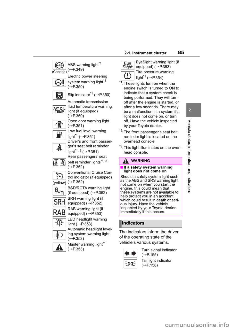
The indicators inform the driver
of the operating state of the
vehicle’s various systems.
(Canada)
ABS warning light*1
( P.349)
Electric power steering
system warning light
*1
( P.350)
Slip indicator
*1 ( P.350)
Automatic transmission
fluid temperature warning
light (if equipped)
( P.350)
Open door warning light
( P.351)
Low fuel level warning
light
*1 ( P.351)
Driver’s and front passen-
ger’s seat belt reminder
light
*1, 2 ( P.351)
Rear passengers’ seat
belt reminder lights
*1, 3
( P.352)
(yellow) Conventional Cruise Con-
trol indicator (if equipped)
(
P.352)
BSD/RCTA warning light
(if equipped) ( P.352)
SRH warning light (if
equipped) ( P.352)
RAB warning light (if
equipped) ( P.353)
LED headlight warning
light ( P.353)
Automatic headlight level-
ing system warning light
( P.353)
Master warning light
*1
( P.353)
EyeSight warning light (if
equipped) ( P.353)
Tire pressure warning
light
*1 ( P.354)
WARNING
■If a safety system warning
light does not come on
Should a safety system light such
as the ABS and SRS warning light
not come on when you start the
engine, this could mean that
these systems are not available to
help protect you in an accident,
which could result in death or seri-
ous injury. Have the vehicle
inspected by you r Toyota dealer
immediately if this occurs.
Indicators
Turn signal indicator
( P.155)
Tail light indicator
( P.158)
Page 86 of 449
862-1. Instrument cluster
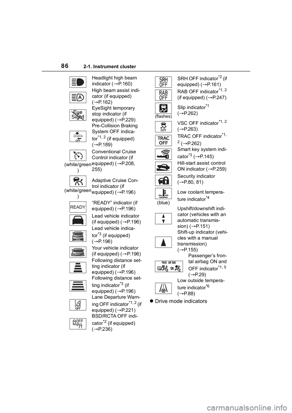
Drive mode indicators
Headlight high beam
indicator ( P.160)
High beam assist indi-
cator (if equipped)
( P.162)
EyeSight temporary
stop indicator (if
equipped) (P.229)
Pre-Collision Braking
System OFF indica-
tor
*1, 2 (if equipped)
( P.189)
(white/green ) Conventional Cruise
Control indicator (if
equipped) (P.208,
255)
(white/green ) Adaptive Cruise Con-
trol indicator (if
equipped) (P.196)
“READY” indicator (if
equipped) (P.196)
Lead vehicle indicator
(if equipped) (
P.196)
Lead vehicle indica-
tor
*3 (if equipped)
( P.196)
Your vehicle indicator
(if equipped) ( P.196)
Following distance set-
ting indicator (if
equipped) (P.196)
Following distance set-
ting indicator
*3 (if
equipped) (P.196)
Lane Departure Warn-
ing OFF indicator
*1, 2 ( i f
equipped) (P.221)
BSD/RCTA OFF indi-
cator
*2 (if equipped)
( P.236)
SRH OFF indicator*2 ( i f
equipped) ( P.161)
RAB OFF indicator
*1, 2
(if equipped) ( P.247)
(flashes)
Slip indicator*1
( P.262)
VSC OFF indicator
*1, 2
( P.263)
TRAC OFF indicator
*1,
2
( P.262)
Smart key system indi-
cator
*3 ( P.145)
Hill-start assist control
ON indicator ( P.259)
Security indicator
( P.80, 81)
(blue) Low coolant tempera-
ture indicator
*4
Upshift/downshift indi-
cator (vehicles with an
automatic transmis-
sion) (
P.151)
Shift-up indicator (vehi-
cles with a manual
transmission)
( P.155)
Passenger’s fron-
tal airbag ON and
OFF indicator
*1, 5
( P. 2 9 )
Low outside tempera-
ture indicator
*6
( P. 8 8 )
Page 87 of 449

872-1. Instrument cluster
2
Vehicle status information and indicators
Normal mode
TRACK mode
*1: These lights turn on when the engine switch is turned to ON to
indicate that a system check is
being performed. They will turn
off after the engine is started, or
after a few seconds. There may
be a malfunction in a system if a
light does not co me on, or turn
off. Have the vehicle inspected
by your Toyota dealer.
*2: The light comes on when the system is turned off.
*3: This light illuminates on the multi-information display.
*4: This indicator turns on when the engine coolant temperature is
low.
*5: This light illuminates on the over-head console.
*6: When the outside temperature is approximately 37°F (3°C) or
lower, this indicator will illumi-
nate. Snow mode indicator (if
equipped) (P.258)
“SPORT” indicator (if
equipped) (P.258)
Snow mode indicator (if
equipped) ( P.258)
“SPORT” indicator (if
equipped) ( P.258)
“TRACK” indicator
( P.263)
SNOW
SPORT
Page 91 of 449
912-1. Instrument cluster
2
Vehicle status information and indicators
played.
■Display items
Odometer
Displays the total distance the vehi-
cle has been driven.
Trip meter A/Trip meter B
Displays the distan ce the vehicle
has been driven si nce the meter
was last reset. Trip meters A and B
can be used to record and display
different distances independently.
To reset, display the desired trip
meter and press and hold the dis-
play change button.
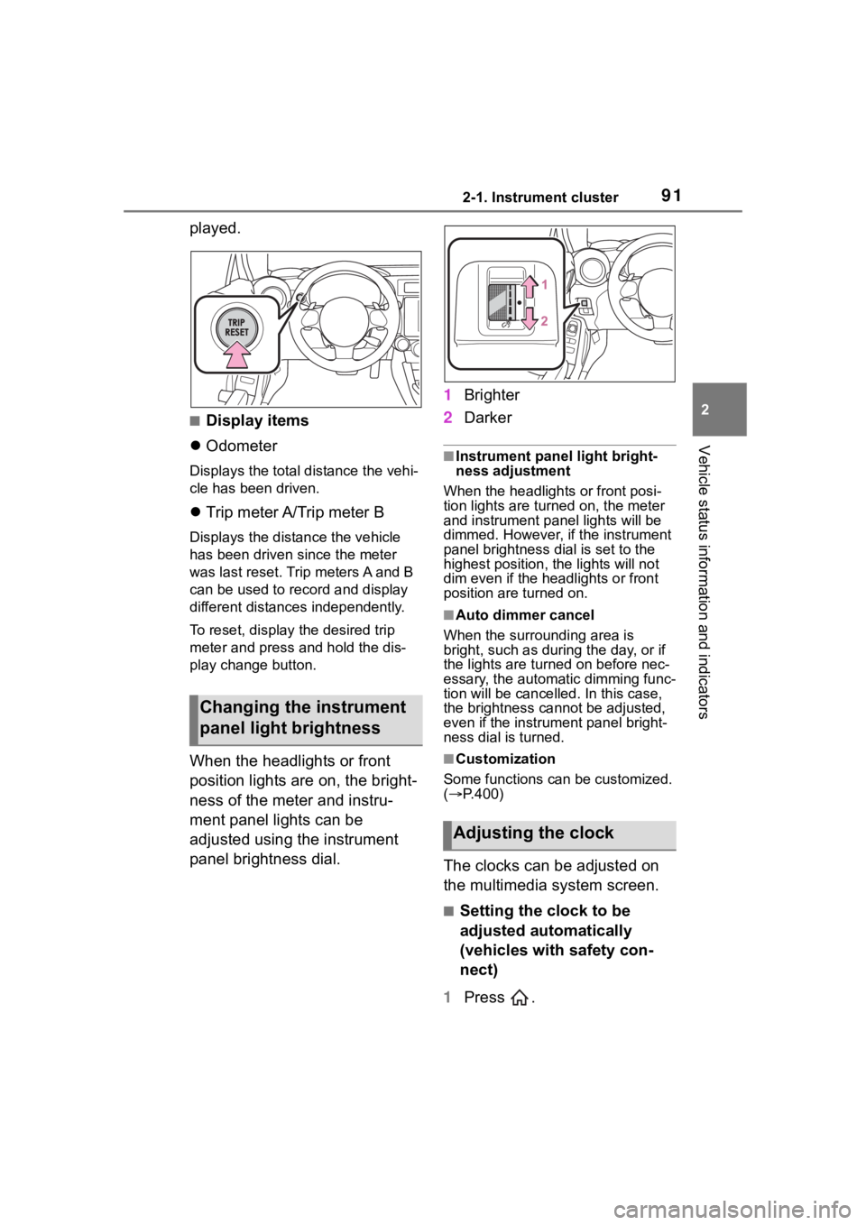
When the headlights or front
position lights are on, the bright-
ness of the meter and instru-
ment panel lights can be
adjusted using the instrument
panel brightness dial. 1
Brighter
2 Darker
■Instrument panel light bright-
ness adjustment
When the headlights or front posi-
tion lights are turned on, the meter
and instrument pa nel lights will be
dimmed. However, if the instrument
panel brightness dial is set to the
highest position, the lights will not
dim even if the headlights or front
position are turned on.
■Auto dimmer cancel
When the surrounding area is
bright, such as during the day, or if
the lights are turned on before nec-
essary, the automatic dimming func-
tion will be cancelled . In this case,
the brightness cannot be adjusted,
even if the instrument panel bright-
ness dial is turned.
■Customization
Some functions can be customized.
( P.400)
The clocks can be adjusted on
the multimedia system screen.
■Setting the clock to be
adjusted automatically
(vehicles with safety con-
nect)
1 Press .
Changing the instrument
panel light brightness
Adjusting the clock
Page 94 of 449
942-1. Instrument cluster
*: Displayed when the navigation system of Apple CarPlay or
Android Auto is operating. For
details, refer to the “MULTIMEDIA
OWNER’S MANUAL”.
■Liquid crystal display
Small spots or light spots may
appear on the display. This phenom-
enon is characteristi c of liquid crys-
tal displays, and there is no problem
continuing to use the display.
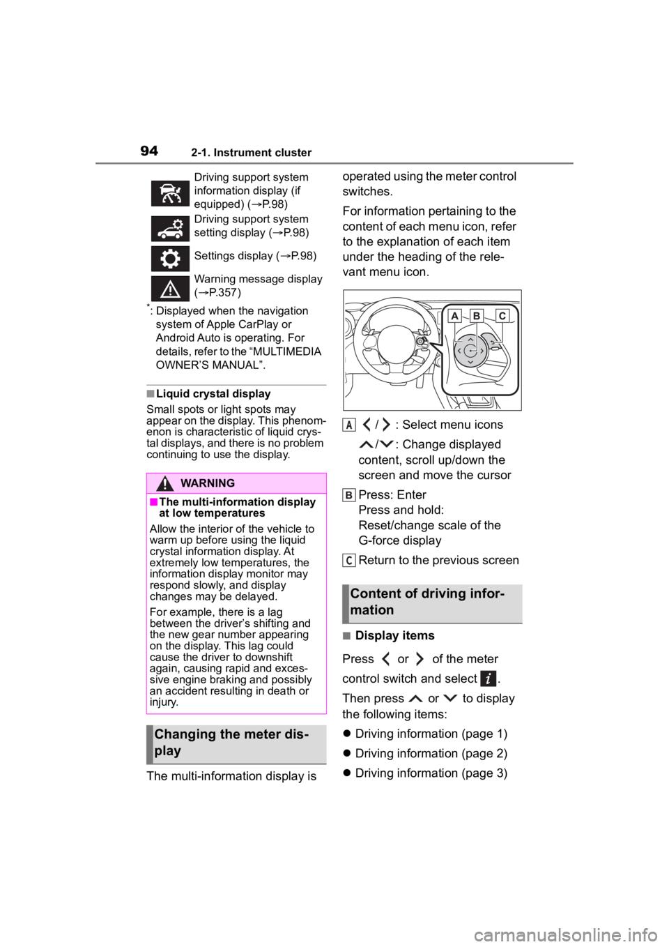
The multi-information display is operated using the meter control
switches.
For information pertaining to the
content of each menu icon, refer
to the explanation of each item
under the heading of the rele-
vant menu icon.
/ : Select menu icons
/ : Change displayed
content, scroll up/down the
screen and move the cursor
Press: Enter
Press and hold:
Reset/change scale of the
G-force display
Return to the previous screen
■Display items
Press or of the meter
control switch and select .
Then press or to display
the following items:
Driving information (page 1)
Driving information (page 2)
Driving information (page 3)
Driving support system
information display (if
equipped) ( P. 9 8 )
Driving support system
setting display ( P. 9 8 )
Settings display ( P. 9 8 )
Warning message display
( P.357)
WARNING
■The multi-information display
at low temperatures
Allow the interior of the vehicle to
warm up before u sing the liquid
crystal informat ion display. At
extremely low temperatures, the
information display monitor may
respond slowly, and display
changes may be delayed.
For example, there is a lag
between the driver’s shifting and
the new gear number appearing
on the display. This lag could
cause the driver to downshift
again, causing rapid and exces-
sive engine braking and possibly
an accident resulting in death or
injury.
Changing the meter dis-
play
Content of driving infor-
mation
A
C
Page 98 of 449
982-1. Instrument cluster
screen: Press .
To change to the top screen: Press .
Operating the measurement
screen
: Start/stop measurement
: Mark off one lap
: Reset measured lap times
: Scroll through the lap
times
Resetting measured lap times
After stopping the measurement,
press .
To display other content while
the stopwatch is operating
If the measurement screen is dis-
played, press to display the top
screen.
Then operate the meter control
switches to display other content.
While other items are displayed,
the measurement will continue but
the stopwatch cannot be operated.
Select to display the route guid-
ance information.
Select to enable selection of an
audio source or track on the dis-
play using the meter control switches.
Select to display the operational
status of the Adaptive Cruise
Control system (
P.190, 207)
The settings of the following
systems can be changed.
LDW (Lane Departure Warn-
ing) (if equipped)
PCB (Pre-Colli sion Braking)
(if equipped)
BSD/RCTA (if equipped)
RAB (Reverse Automatic
Braking system) (if equipped)
(Sonar Audible Alarm) (if
equipped)
SRH (Steering Responsive
Headlight) (if equipped)■Meter display settings that
can be changed
Units
Select to change the units of mea-
sure displayed.
Startup Scrn
Navigation system-linked
display
Audio system-linked dis-
play
Driving support system
information display (if
equipped)
Driving support system
setting display
Settings display
Page 103 of 449
1033-1. Key information
3
Before driving
The electronic keys are
equipped with the following
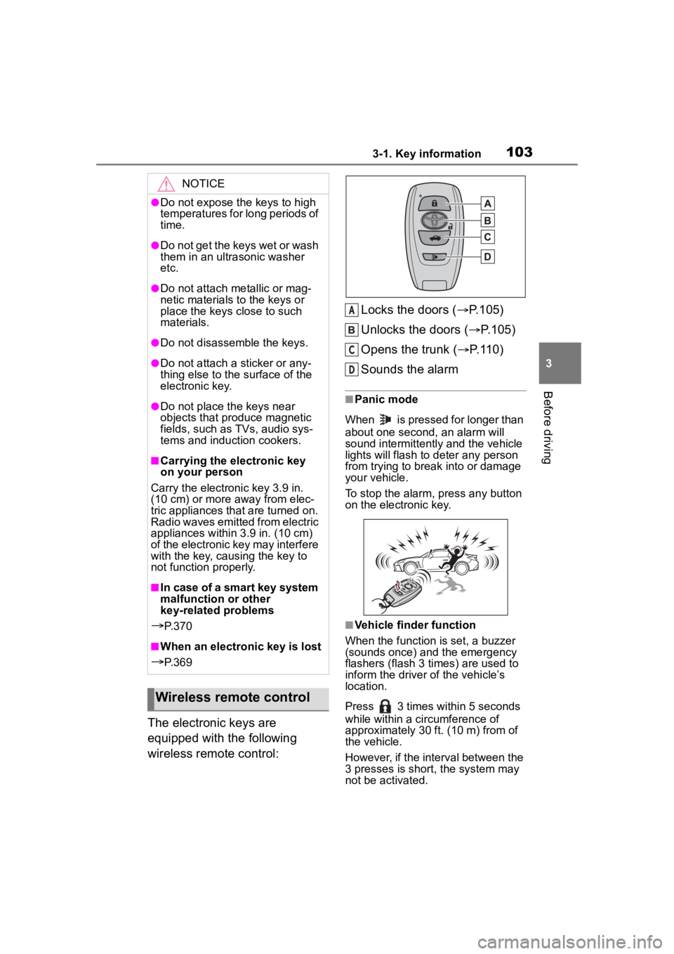
wireless remote control:Locks the doors (
P.105)
Unlocks the doors ( P.105)
Opens the trunk ( P.110)
Sounds the alarm
■Panic mode
When is pressed for longer than
about one second, an alarm will
sound intermittently and the vehicle
lights will flash to deter any person
from trying to break into or damage
your vehicle.
To stop the alarm, press any button
on the electronic key.
■Vehicle finder function
When the function is set, a buzzer
(sounds once) and the emergency
flashers (flash 3 times) are used to
inform the driver of the vehicle’s
location.
Press 3 times within 5 seconds
while within a ci rcumference of
approximately 30 ft. (10 m) from of
the vehicle.
However, if the interval between the
3 presses is short, the system may
not be activated.
NOTICE
●Do not expose the keys to high
temperatures for long periods of
time.
●Do not get the keys wet or wash
them in an ultrasonic washer
etc.
●Do not attach metallic or mag-
netic materials to the keys or
place the keys close to such
materials.
●Do not disassemble the keys.
●Do not attach a sticker or any-
thing else to the surface of the
electronic key.
●Do not place th e keys near
objects that produce magnetic
fields, such as TVs, audio sys-
tems and induction cookers.
■Carrying the electronic key
on your person
Carry the electronic key 3.9 in.
(10 cm) or more away from elec-
tric appliances that are turned on.
Radio waves emitted from electric
appliances within 3.9 in. (10 cm)
of the electronic key may interfere
with the key, causing the key to
not function properly.
■In case of a smart key system
malfunction or other
key-related problems
P. 3 7 0
■When an electronic key is lost
P. 3 6 9
Wireless remote control
A
C
D