Page 70 of 449

701-2. Child safety
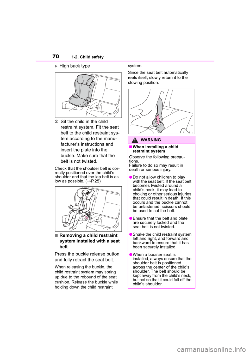
High back type
2 Sit the child in the child
restraint system. Fit the seat
belt to the child restraint sys-
tem according to the manu-
facturer’s instructions and
insert the plate into the
buckle. Make sure that the
belt is not twisted.
Check that the shoulder belt is cor-
rectly positioned over the child’s
shoulder and that the lap belt is as
low as possible. ( P.25)
■Removing a child restraint
system installed with a seat
belt
Press the buckle release button
and fully retract the seat belt.
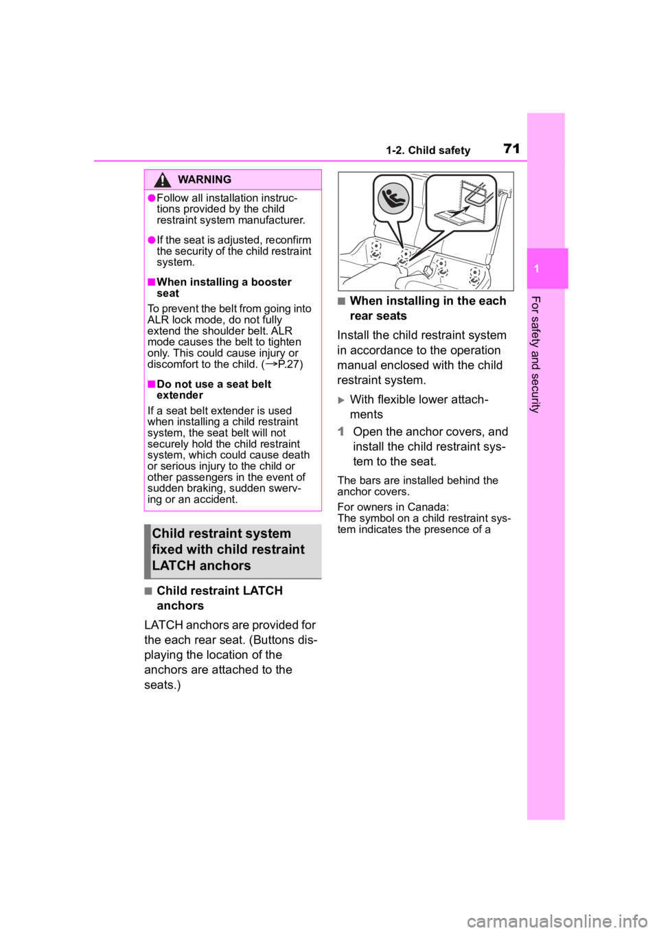
When releasing the buckle, the
child restraint system may spring
up due to the rebound of the seat
cushion. Release the buckle while
holding down the child restraint system.
Since the seat belt automatically
reels itself, slowly return it to the
stowing position.
WARNING
■When installing a child
restraint system
Observe the following precau-
tions.
Failure to do so may result in
death or serious injury.
●Do not allow children to play
with the seat belt. If the seat belt
becomes twisted around a
child’s neck, it may lead to
choking or other serious injuries
that could result in death. If this
occurs and the buckle cannot
be unfastened, scissors should
be used to cut the belt.
●Ensure that the belt and plate
are securely locked and the
seat belt is not twisted.
●Shake the child restraint system
left and right, and forward and
backward to ensure that it has
been securely installed.
●When a booster seat is
installed, always ensure that the
shoulder belt is positioned
across the center of the child’s
shoulder. The belt should be
kept away from the child’s neck,
but not so that it could fall off the
child’s shoulder.
Page 71 of 449

711-2. Child safety
1
For safety and security
■Child restraint LATCH
anchors
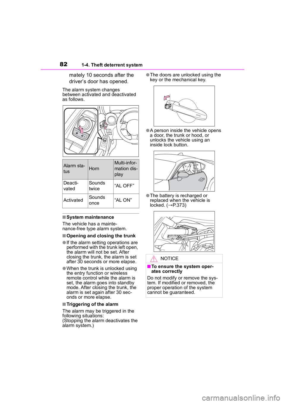
LATCH anchors are provided for
the each rear seat. (Buttons dis-
playing the location of the
anchors are attached to the
seats.)
■When installing in the each
rear seats
Install the child restraint system
in accordance to the operation
manual enclosed with the child
restraint system.
With flexible lower attach-
ments
1 Open the anchor covers, and
install the child restraint sys-
tem to the seat.
The bars are installed behind the
anchor covers.
For owners in Canada:
The symbol on a child restraint sys-
tem indicates the presence of a
WARNING
●Follow all installation instruc-
tions provided by the child
restraint system manufacturer.
●If the seat is adjusted, reconfirm
the security of the child restraint
system.
■When installing a booster
seat
To prevent the belt from going into
ALR lock mode, do not fully
extend the shoulder belt. ALR
mode causes the belt to tighten
only. This could cause injury or
discomfort to the child. (
P. 2 7 )
■Do not use a seat belt
extender
If a seat belt extender is used
when installing a child restraint
system, the seat belt will not
securely hold the child restraint
system, which could cause death
or serious injury to the child or
other passengers in the event of
sudden braking, sudden swerv-
ing or an accident.
Child restraint system
fixed with child restraint
LATCH anchors
Page 81 of 449

811-4. Theft deterrent system
1
For safety and security
■Items to check before lock-
ing the vehicle
To prevent unexpected trigger-
ing of the alarm and vehicle
theft, make sure of the following:
Nobody is in the vehicle.
The windows are closed
before the alarm is set.
No valuables or other per-
sonal items are left in the
vehicle.
■Setting
Close the doors, trunk and hood, and lock both side doors
using the entry function or wire-
less remote control. The system
will set automatically after 30
seconds.
The indicator light changes from
being on to flashing when the sys-
tem is set.
■Canceling or stopping
Do one of the following to deac-
tivate or stop the alarms:
Unlock the doors or open the
trunk using the entry function
or wireless remote control.
Turn the engine switch to
ACC or ON, or start the
engine.
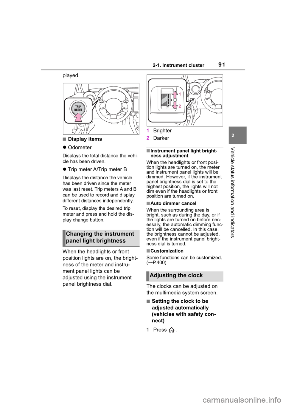
1 Check that both side doors
and the trunk are closed.
2 Turn the engine switch to
ON.
3 Open the driver’s door while
pressing and holding on
the door lock switch and con-
tinue to press for approxi-
Alarm
The alarm’s default setting
is set to off. To use the
alarm, perform the activat-
ing the alarm system proce-
dures.
The alarm uses light and
sound to give an alert when
an intrusion is detected.
The alarm is triggered in the
following situations when
the alarm is set:
A locked door or trunk is
unlocked or opened in any
way other than using the
entry function or wireless
remote control.
The hood is opened.
Setting/canceling/stop-
ping the alarm system
Activating/deactivating
the alarm system
Page 82 of 449

821-4. Theft deterrent system
mately 10 seconds after the
driver’s door has opened.
The alarm system changes
between activated and deactivated
as follows.
■System maintenance
The vehicle has a mainte-
nance-free type alarm system.
■Opening and closing the trunk
●If the alarm setting operations are
performed with the trunk left open,
the alarm will not be set. After
closing the trunk, the alarm is set
after 30 seconds or more elapse.
●When the trunk is unlocked using
the entry function or wireless
remote control while the alarm is
set, the alarm goes into standby
mode. After closing the trunk, the
alarm is set again after 30 sec-
onds or more elapse.
■Triggering of the alarm
The alarm may be triggered in the
following situations:
(Stopping the alarm deactivates the
alarm system.)
●The doors are unlocked using the
key or the mechanical key.
●A person inside the vehicle opens
a door, the trunk or hood, or
unlocks the vehicle using an
inside lock button.
●The battery is recharged or
replaced when the vehicle is
locked. ( P.373)
Alarm sta-
tusHorn
Multi-infor-
mation dis-
play
Deacti-
vatedSounds
twice“AL OFF”
ActivatedSounds
once“AL ON”
NOTICE
■To ensure the system oper-
ates correctly
Do not modify or remove the sys-
tem. If modified or removed, the
proper operation of the system
cannot be guaranteed.
Page 88 of 449
882-1. Instrument cluster
■Locations of gauges and meters
Normal modeMulti-information display
Presents the driver with a variety of vehicle data (P.93)
Displays warning messages in case of a malfunction (P.357)
Tachometer
Displays the engine speed in revolutions per minute
The red zone will be lower than n ormal, when the engine is cold
Outside temperature
Displays the outside temperature within the range of -40°F (-40 °C) to 122°F
(50°C). Low outside temperature indicator comes on when the amb ient
temperature is 37°F (3°C) or lower.
Clock
Engine coolant temperature gauge
Displays the engine c oolant temperature
Fuel gauge
Speedometer
Shift position and gear position ( P.149, 154)
Odometer and trip meter display ( P.90)
Gauges and meters
Meter display
A
C
D
Page 89 of 449

892-1. Instrument cluster
2
Vehicle status information and indicators
TRACK modeMulti-information display
Presents the driver with a variety of vehicle data (P.93)
Displays warning messages in case of a malfunction (P.357)
Tachometer
Displays the engine speed in revolutions per minute
The red zone will be lower than n ormal, when the engine is cold
Outside temperature
Displays the outside temperature within the range of -40°F (-40 °C) to 122°F
(50°C). Low outside temperature indicator comes on when the amb ient
temperature is 37°F (3°C) or lower.
Clock
Engine coolant temperature gauge
Displays the engine c oolant temperature
Fuel gauge
Speedometer
Shift position and gear position ( P.149, 154)
Odometer and trip meter display ( P.90)
■REV indicator
When the engine speed reaches
a set speed, the shift position
and shift range indicator will illu-
minate in orange and a buzzer
will sound. If the engine speed enters the red zone, the shift
position and shift range indicator
will illuminate in red.
The default setting for the REV indi-
cator is disabled. The setting can
be enabled/disabled on of the
A
C
D
Page 91 of 449

912-1. Instrument cluster
2
Vehicle status information and indicators
played.
■Display items
Odometer
Displays the total distance the vehi-
cle has been driven.
Trip meter A/Trip meter B
Displays the distan ce the vehicle
has been driven si nce the meter
was last reset. Trip meters A and B
can be used to record and display
different distances independently.
To reset, display the desired trip
meter and press and hold the dis-
play change button.
When the headlights or front
position lights are on, the bright-
ness of the meter and instru-
ment panel lights can be
adjusted using the instrument
panel brightness dial. 1
Brighter
2 Darker
■Instrument panel light bright-
ness adjustment
When the headlights or front posi-
tion lights are turned on, the meter
and instrument pa nel lights will be
dimmed. However, if the instrument
panel brightness dial is set to the
highest position, the lights will not
dim even if the headlights or front
position are turned on.
■Auto dimmer cancel
When the surrounding area is
bright, such as during the day, or if
the lights are turned on before nec-
essary, the automatic dimming func-
tion will be cancelled . In this case,
the brightness cannot be adjusted,
even if the instrument panel bright-
ness dial is turned.
■Customization
Some functions can be customized.
( P.400)
The clocks can be adjusted on
the multimedia system screen.
■Setting the clock to be
adjusted automatically
(vehicles with safety con-
nect)
1 Press .
Changing the instrument
panel light brightness
Adjusting the clock
Page 92 of 449
922-1. Instrument cluster
2Select .
3 Select “General”.
4 Select “Clock”.
5 Select “Time Setting”.
6 Select “AUTO”.
The clock will be set automati-
cally where a GPS signal is
available.
■Setting the clock to be
adjusted automatically
(vehicles without safety
connect)
1 Press .
2 Select .
3 Select “General”.
4 Select “Clock”.
5 Select “Time Setting”.
6 Select “Sync With Phone”.
The clock will be set and
adjusted automatically when a
smartphone is connected via
Bluetooth
®for transferring
phonebook data. For details,
refer to the “MULTIMEDIA
OWNER’S MANUAL”.
■Adjusting the clock manu-
ally
1 Press .
2 Select .
3 Select “General”.
4 Select “Clock”.
5 Select “Time Setting”. 6
Select “Manual” then adjust
the clock.
7 Select “OK”.
■Changing the clock
between 12H/24H format
1 Press .
2 Select .
3 Select “General”.
4 Select “Clock”.
5 Select “12H” or “24H”.
■Clock settings screen
The clock setting screen can also be
displayed by touch ing the clock on
the status bar.