2023 TOYOTA 86 warning
[x] Cancel search: warningPage 249 of 449

2494-6. Using other driving systems
4
Driving
When the settings cannot be
changed, the ON/OFF setting key
will be grayed out.
Also, the following settings can be
changed by operating the multime-
dia system screen. (P.400)
●Warning Volume
●Sonar Audible Alarm
●Automatic Braking
If the Reverse Automatic Brak-
ing (RAB) system malfunctions,
the above indicator illuminates
on the meter. Contact the near-
est Toyota dealer for details.
The 4 sonar sensors are located
in the rear bumper. To ensure
the proper operation of the
Reverse Automatic Braking
(RAB) system, observe the fol-
lowing precautions.
Do not affix any stickers or
other items on the sonar sen-
sor or the bumper surface
near the sonar sensors.
Always keep the sonar sensor and the rear bumper surface
near the sonar sensors clean.
Do not modify rear bumper.
Do not paint the bumper near
the sonar sensors.
Do not apply high pressure
water to the sonar sensors
with a high pressure
car-washing machine.
Do not apply strong impacts
to the rear bumper near the
sonar sensors. If a sensor
becomes misaligned, a sys-
tem malfunction may occur,
including inability to detect
objects in the reversing direc-
tion. If any strong impact is
applied to the rear bumper,
contact a Toyota dealer to
have the system inspected.
Do not disassemble the sonar
sensors.
If the sonar sensors require repair or
replacement, or if the area of the
rear bumper near the sonar sensors
requires repair, paintwork or
replacement, contact your Toyota
dealer for assistance.
RAB warning light
Handling of the Sonar
Sensors
Page 250 of 449
2504-6. Using other driving systems
●Do not wipe the camera with alco-
hol, benzine or paint thinner.
Otherwise, discoloration may
occur. To remove contamination,
wipe the camera with a cloth
moistened with a diluted neutral
detergent. Then wipe it with a soft,
dry cloth.
●When waxing the vehicle, be care-
ful not to apply the wax to the
camera. If it comes in contact with
the camera, moisten a clean cloth
with a diluted neutral detergent to
remove the wax.
●The camera lens has a hard coat-
ing to help prevent scratches.
However, when washing the vehi-
cle or cleaning the camera lens,
be careful not to scratch the cam-
era lens. Do not use a washing
brush directly on the camera lens.
The image quality of the rear view
camera may deteriorate.
●Strong light shined on the camera lens may develop vertical lines
around the light source. This is not
a malfunction.
●Under the fluore
scent light, the
display may flicker. However, this
is not a malfunction.
●The image of the rear view cam-
era may be slightly different from
the actual color of the objects.
●If there is a mal function on the
multimedia system screen, refer to
“MULTIMEDIA OWNER'S MAN-
UAL”.
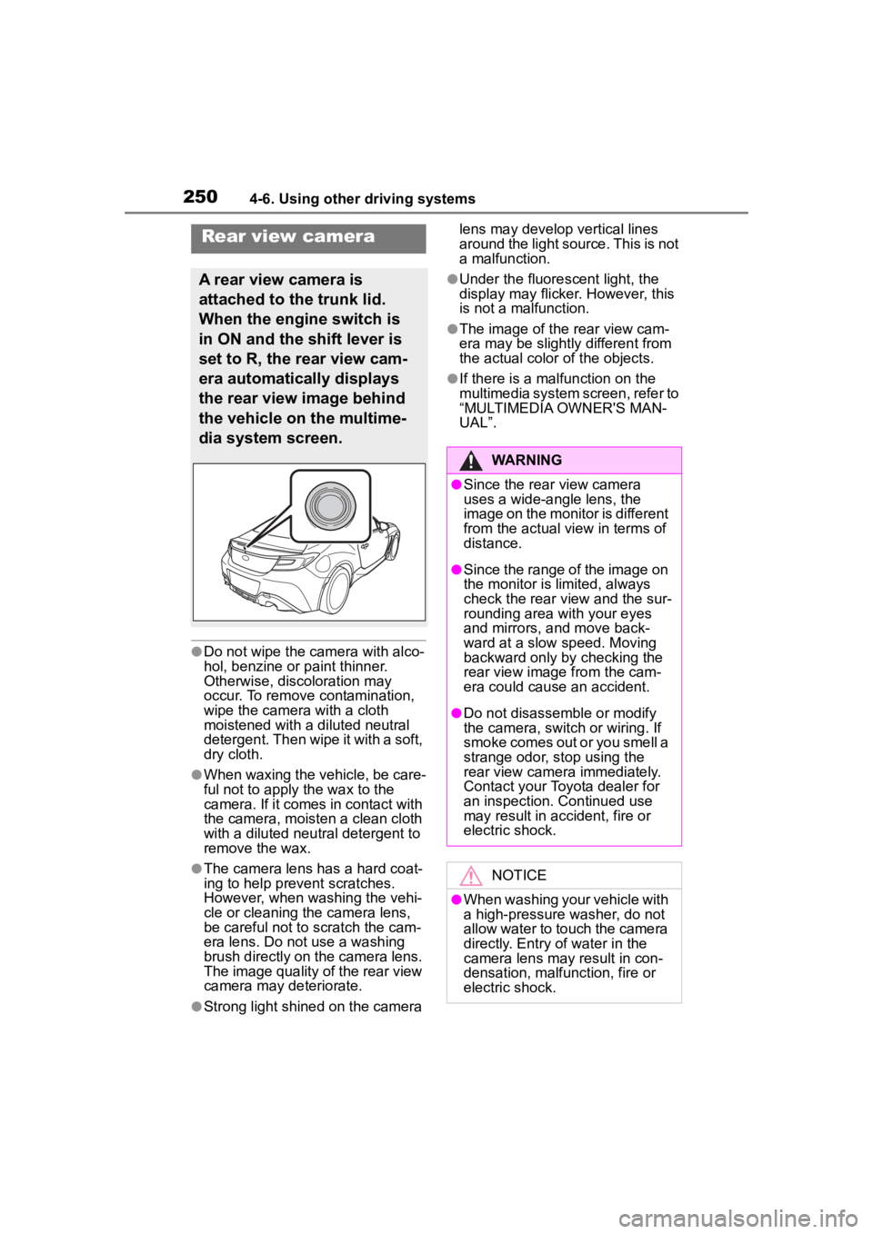
Rear view camera
A rear view camera is
attached to the trunk lid.
When the engine switch is
in ON and the shift lever is
set to R, the rear view cam-
era automatically displays
the rear view image behind
the vehicle on the multime-
dia system screen.
WARNING
●Since the rear view camera
uses a wide-angle lens, the
image on the monitor is different
from the actual view in terms of
distance.
●Since the range of the image on
the monitor is limited, always
check the rear view and the sur-
rounding area with your eyes
and mirrors, and move back-
ward at a slow speed. Moving
backward only by checking the
rear view image from the cam-
era could cause an accident.
●Do not disassemble or modify
the camera, switch or wiring. If
smoke comes out or you smell a
strange odor, stop using the
rear view camera immediately.
Contact your Toyota dealer for
an inspection. Continued use
may result in accident, fire or
electric shock.
NOTICE
●When washing your vehicle with
a high-pressure washer, do not
allow water to touch the camera
directly. Entry of water in the
camera lens may result in con-
densation, malfunction, fire or
electric shock.
Page 252 of 449
2524-6. Using other driving systems
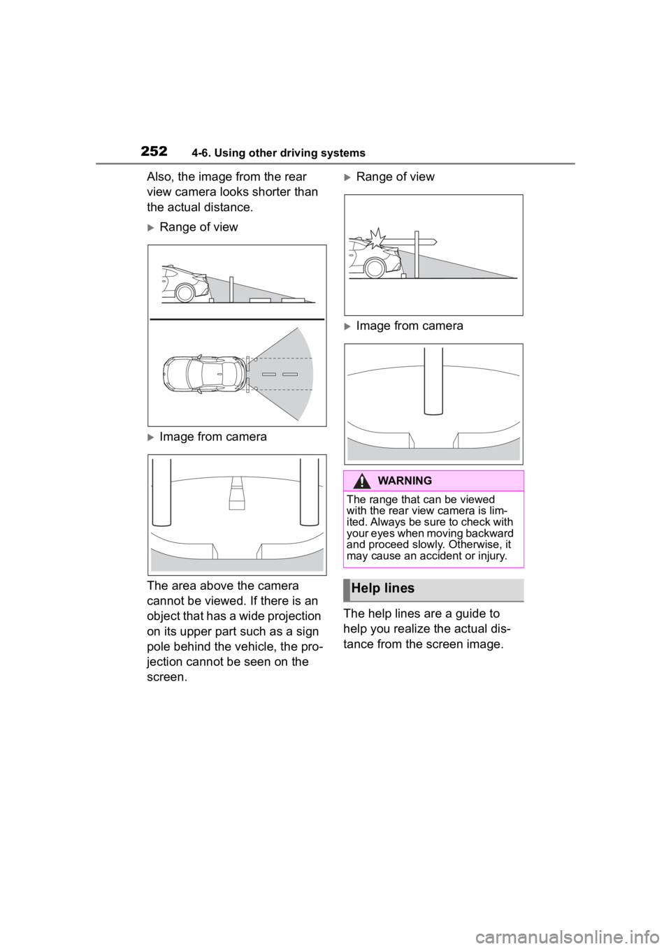
Also, the image from the rear
view camera looks shorter than
the actual distance.
Range of view
Image from camera
The area above the camera
cannot be viewed. If there is an
object that has a wide projection
on its upper part such as a sign
pole behind the vehicle, the pro-
jection cannot be seen on the
screen.
Range of view
Image from camera
The help lines are a guide to
help you realize the actual dis-
tance from the screen image.
WARNING
The range that can be viewed
with the rear vie w camera is lim-
ited. Always be sure to check with
your eyes when moving backward
and proceed slowly. Otherwise, it
may cause an accident or injury.
Help lines
Page 253 of 449
2534-6. Using other driving systems
4
Driving
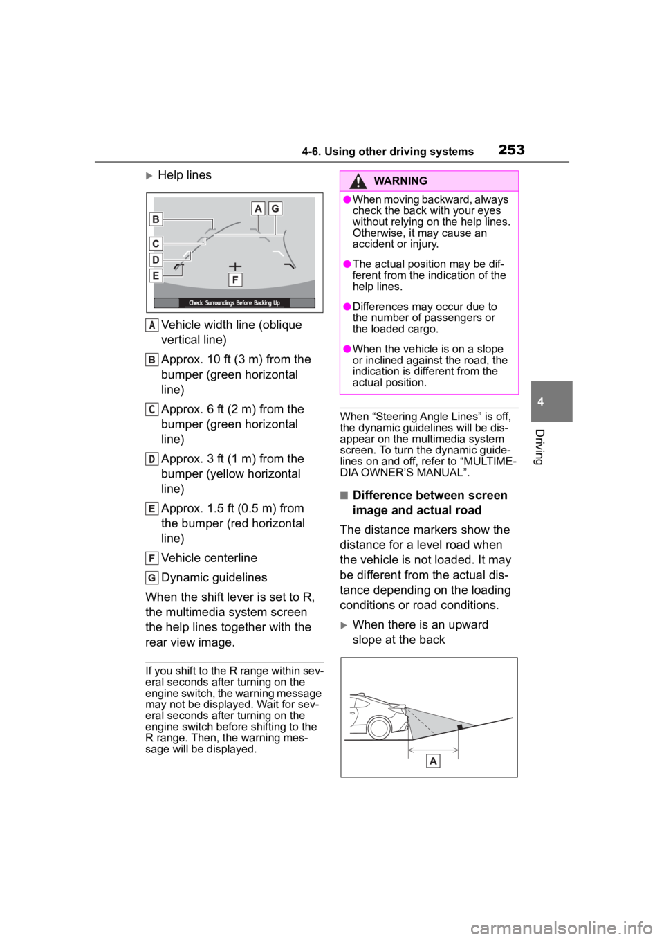
Help linesVehicle width line (oblique
vertical line)
Approx. 10 ft (3 m) from the
bumper (green horizontal
line)
Approx. 6 ft (2 m) from the
bumper (green horizontal
line)
Approx. 3 ft (1 m) from the
bumper (yellow horizontal
line)
Approx. 1.5 ft (0.5 m) from
the bumper (red horizontal
line)
Vehicle centerline
Dynamic guidelines
When the shift lever is set to R,
the multimedia system screen
the help lines together with the
rear view image.
If you shift to the R range within sev-
eral seconds after turning on the
engine switch, the warning message
may not be displayed. Wait for sev-
eral seconds after turning on the
engine switch before shifting to the
R range. Then, the warning mes-
sage will be displayed.
When “Steering Angle Lines” is off,
the dynamic guidelines will be dis-
appear on the multimedia system
screen. To turn the dynamic guide-
lines on and off, refer to “MULTIME-
DIA OWNER’S MANUAL”.
■Difference between screen
image and actual road
The distance markers show the
distance for a level road when
the vehicle is not loaded. It may
be different from the actual dis-
tance depending on the loading
conditions or road conditions.
When there is an upward
slope at the back
A
C
D
WARNING
●When moving backward, always
check the back with your eyes
without relying on the help lines.
Otherwise, it may cause an
accident or injury.
●The actual position may be dif-
ferent from the in dication of the
help lines.
●Differences may occur due to
the number of passengers or
the loaded cargo.
●When the vehicle is on a slope
or inclined against the road, the
indication is dif ferent from the
actual position.
Page 255 of 449
2554-6. Using other driving systems
4
Driving
●Conventional Cruise Control
enables you to maintain a con-
stant vehicle speed without hold-
ing your foot on the accelerator
pedal and it is operative when the
vehicle speed is 20 mph (30 km/h)
or more.
●Make sure the Conventional
Cruise Control system is turned
off when the Conventional Cruise
Control is not in use to avoid unin-
tentionally setting of the Conven-
tional Cruise Control.
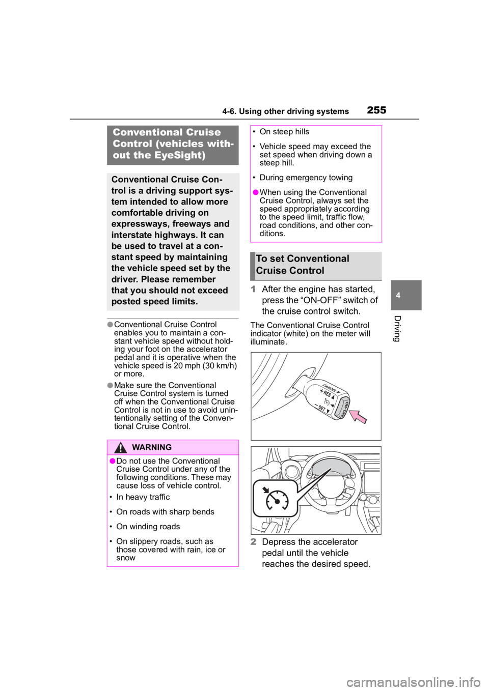
1After the engine has started,
press the “ON-OFF” switch of
the cruise control switch.
The Conventional Cruise Control
indicator (white) on the meter will
illuminate.
2Depress the accelerator
pedal until the vehicle
reaches the desired speed.
Conventional Cruise
Control (vehicles with-
out the EyeSight)
Conventional Cruise Con-
trol is a driving support sys-
tem intended to allow more
comfortable driving on
expressways, freeways and
interstate highways. It can
be used to travel at a con-
stant speed by maintaining
the vehicle speed set by the
driver. Please remember
that you should not exceed
posted speed limits.
WARNING
●Do not use the Conventional
Cruise Control under any of the
following conditions. These may
cause loss of vehicle control.
• In heavy traffic
• On roads with sharp bends
• On winding roads
• On slippery roads, such as those covered with rain, ice or
snow
• On steep hills
• Vehicle speed may exceed the set speed when d riving down a
steep hill.
• During emergency towing
●When using the Conventional
Cruise Control, always set the
speed appropriately according
to the speed limit, traffic flow,
road conditions, and other con-
ditions.
To set Conventional
Cruise Control
Page 260 of 449
2604-6. Using other driving systems
3Start the engine and check
that the ABS warning light
and slip indicator are off.
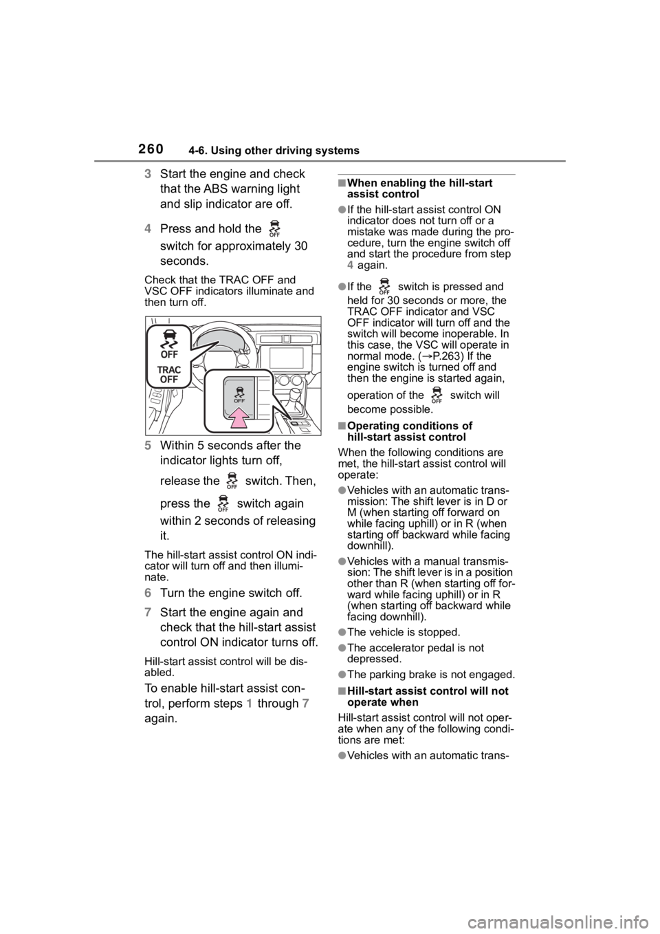
4 Press and hold the
switch for approximately 30
seconds.
Check that the TRAC OFF and
VSC OFF indicators illuminate and
then turn off.
5 Within 5 seconds after the
indicator lights turn off,
release the switch. Then,
press the switch again
within 2 seconds of releasing
it.
The hill-start assis t control ON indi-
cator will turn off and then illumi-
nate.
6 Turn the engine switch off.
7 Start the engine again and
check that the hill-start assist
control ON indicator turns off.
Hill-start assist control will be dis-
abled.
To enable hill-start assist con-
trol, perform steps 1 through 7
again.
■When enabling the hill-start
assist control
●If the hill-start assist control ON
indicator does n ot turn off or a
mistake was made during the pro-
cedure, turn the e ngine switch off
and start the procedure from step
4 again.
●If the switch is pressed and
held for 30 seconds or more, the
TRAC OFF indicator and VSC
OFF indicator will tu rn off and the
switch will become inoperable. In
this case, the VSC will operate in
normal mode. ( P.263) If the
engine switch is turned off and
then the engine is started again,
operation of the switch will
become possible.
■Operating conditions of
hill-start assist control
When the following conditions are
met, the hill-start assist control will
operate:
●Vehicles with an automatic trans-
mission: The shift lever is in D or
M (when starting off forward on
while facing uphill) or in R (when
starting off backward while facing
downhill).
●Vehicles with a manual transmis-
sion: The shift lever is in a position
other than R (when starting off for-
ward while facing uphill) or in R
(when starting off backward while
facing downhill).
●The vehicle is stopped.
●The accelerator pedal is not
depressed.
●The parking brake is not engaged.
■Hill-start assist control will not
operate when
Hill-start assist cont rol will not oper-
ate when any of the following condi-
tions are met:
●Vehicles with an automatic trans-
Page 261 of 449
2614-6. Using other driving systems
4
Driving
mission: The shift lever is in a
position other than D or M (when
facing uphill) or in a position other
than R (when facing downhill).
●Vehicles with a manual transmis-
sion: The shift lever is in R (when
facing uphill) or in a position other
than R (when facing downhill).
●Vehicles with an automatic trans-
mission: The accelerator pedal is
depressed.
●The parking brake is applied.
●Vehicles with a manual transmis-
sion: The clutch is engaged.
●Approximately 2 seconds have
elapsed since the brake pedal
was released.
●The hill-start assist control ON
indicator is not illuminated.
●The engine switch is turned to
ACC or OFF.
■Notes for hill-start assist con-
trol
●A slight jolt may be felt when start-
ing off backward with the shift
lever in R and then moving for-
ward.
●If the braking po wer of hill-start
assist control is insufficient,
depress the brake pedal.
●While the vehicle is stopped,
make sure to depress the brake
pedal.
■The system may be malfunc-
tioning when
In the following si tuations, the sys-
tem may be malfunctioning. Have
the vehicle inspected by your Toyota
dealer.
●The slip indicat or is illuminated.
●The hill-start assist control ON
indicator turns off and a buzzer
sounds.
WARNING
■Hill-start assist control pre-
cautions
●Do not overly rely on hill-start
assist control. Hill-start assist
control may not operate effec-
tively on steep inclines and
roads covered with ice.
●Unlike the parking brake,
hill-start assist control is not
intended to hold the vehicle sta-
tionary for an extended period
of time. Do not attempt to use
hill-start assist control to hold
the vehicle on an incline, as
doing so may lead to an acci-
dent.
●Do not stop the engine while
hill-start assist control is operat-
ing, as hill-start assist control
will stop operating, possibly
leading to an accident.
Page 265 of 449
2654-6. Using other driving systems
4
Driving
WARNING
■The ABS does not operate
effectively when
●The limits of tire gripping perfor-
mance have been exceeded
(such as excessively worn tires
on a snow covered road).
●The vehicle hydroplanes while
driving at high speed on wet or
slick roads.
■Stopping distance when the
ABS is operating may exceed
that of normal conditions
The ABS is not designed to
shorten the vehicle’s stopping dis-
tance. Always maintain a safe dis-
tance from the vehicle in front of
you, especially in the following sit-
uations:
●When driving on d irt, gravel or
snow-covered roads
●When driving with tire chains
●When driving over bumps in the
road
●When driving over roads with
potholes or uneven surfaces
■TRAC may not operate effec-
tively when
Directional control and power may
not be achievable while driving on
slippery road surfaces, even if the
TRAC system is operating. Do not
drive the vehicle in conditions
where stability and power may be
lost.
■When the VSC and/or brake
LSD function is activated
The slip indicator flashes. Always
drive carefully. Reckless driving
may cause an accident. Exercise
particular care wh en the indicator
flashes.
■When the TRAC/VSC systems
are turned off
Be especially careful and drive at
a speed appropriate to the road
conditions. As these are the sys-
tems to help ensure vehicle stabil-
ity and driving force, do not turn
the TRAC/VSC systems off
unless necessary.
■Replacing tires
Make sure that all tires are of the
specified size, brand, tread pat-
tern and total load capacity. In
addition, make sure that the tires
are inflated to the recommended
tire inflation p ressure level.
The ABS, TRAC and VSC sys-
tems will not functi on correctly if
different tires are installed on the
vehicle.
Contact your Toyota dealer for fur-
ther information when replacing
tires or wheels.
■Handling of tires and the sus-
pension
Using tires with any kind of prob-
lem or modifying the suspension
will affect the driving assist sys-
tems, and may cause a system to
malfunction.