Page 493 of 608
4937-2. Steps to take in an emergency
7
When trouble arises
4RUNNER (U)
●Phillips screwdriver
● Stop the vehicle in a safe place on a hard, flat surface.
● Set the parking brake.
● Shift the shift lever to P.
● Stop the engine.
● Turn on the emergency flashers. ( P. 466)
If you have a flat tire
Your vehicle is equipped with a spare tire. The flat tire can be
replaced with the spare tire.
For details about tires: P. 4 2 7
WARNING
■If you have a flat tire
Do not continue driving with a flat tire.
Driving even a short distance wit h a flat tire can damage the tire and the
wheel beyond repair, which cou ld result in an accident.
You will need the following item:
Before jacking up the vehicle
Page 504 of 608

5047-2. Steps to take in an emergency
4RUNNER (U)
WARNING
■Replacing a flat tire
●Observe the following precautions.
Failure to do so may result in serious injury:
• Lower the spare tire completely to the ground before removing it
from under the vehicle.
• Do not try to remove the wheel ornament by hand. Take due care in
handling the ornament to avoi d unexpected personal injury.
• Do not attach a heavily damaged wheel ornament, as it may fly off
the wheel while the vehicle is moving.
• Do not touch the disc wheels or the area around the brakes imm edi-
ately after the vehicle has been driven.
After the vehicle has been driven the disc wheels and the area
around the brakes will be extremely hot. Touching these areas w ith
hands, feet or other body parts while changing a tire, etc. may result
in burns.
●Failure to follow these precautions could cause the wheel nuts to
loosen and the t ire to fall off, resulting in death or serious injury.
• Have the wheel nuts tightened with a torque wrench to 83 ft•lb f (112
N•m, 11.4 kgf•m) steel wheels, 7 6 ft•lbf (103 N•m, 10.5 kgf•m) alumi-
num wheels, as soon as possible after changing wheels.
• When installing a tire, only use wheel nuts that have been spe cifi-
cally designed for that wheel.
• If there are any cracks or deformations in the bolt screws, nu t
threads or bolt holes of the wheel, have the vehicle inspected by
your Toyota dealer.
• When installing the wheel nuts, be sure to install them with t he
tapered ends facing inward.
Page 510 of 608
5107-2. Steps to take in an emergency
4RUNNER (U)
One of the following may be the cause of the problem:
● One or both of the battery t erminals may be disconnected.
● The battery may be discharged. ( P. 515)
Contact your Toyota dealer if the problem cannot be repaired, o r if repair
procedures are unknown.
When the engine does not start, the following steps can be used as an
interim measure to start the engine if the engine switch is fun ctioning
normally:
Set the parking brake.
Shift the shift lever to P.
Turn the engine switch to ACCESSORY mode.
Press and hold the engine switch for about 15 seconds while
depressing the brake pedal firmly.
Even if the engine can be start ed using the above steps, the sy stem
may be malfunctioning. Have the vehicle inspected by your Toyot a
dealer.
The starter motor does not turn over, the interior lights and h ead-
lights do not turn on, o r the horn does not sound.
Emergency start function
1
2
3
4
Page 513 of 608

5137-2. Steps to take in an emergency
7
When trouble arises
4RUNNER (U)
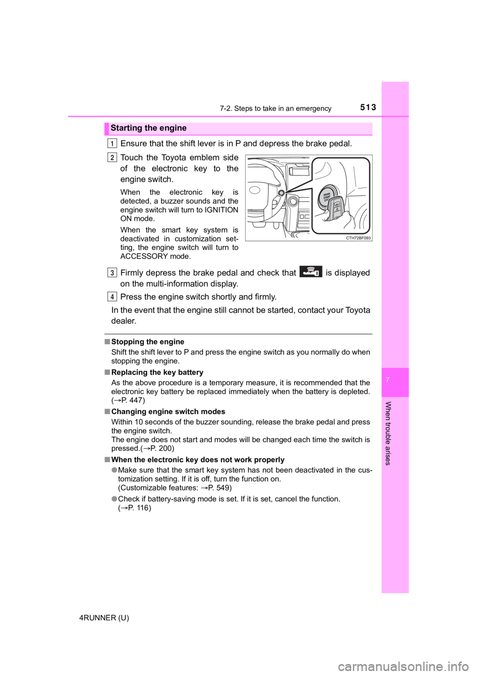
Ensure that the shift lever is in P and depress the brake pedal.
Touch the Toyota emblem side
of the electronic key to the
engine switch.
When the electronic key is
detected, a buzzer sounds and the
engine switch will turn to IGNITION
ON mode.
When the smart key system is
deactivated in customization set-
ting, the engine switch will turn to
ACCESSORY mode.
Firmly depress the brake pedal and check that is displayed
on the multi-information display.
Press the engine switch shortly and firmly.
In the event that the engine still cannot be started, contact your Toyota
dealer.
■ Stopping the engine
Shift the shift lever to P and press the engine switch as you normally do when
stopping the engine.
■ Replacing the key battery
As the above procedure is a temporary measure, it is recommende d that the
electronic key battery be replaced immediately when the battery is depleted.
( P. 447)
■ Changing engine switch modes
Within 10 seconds of the buzzer sounding, release the brake ped al and press
the engine switch.
The engine does not start and modes will be changed each time t he switch is
pressed.( P. 200)
■ When the electronic key does not work properly
●Make sure that the smart key system has not been deactivated in the cus-
tomization setting. If it is off, turn the function on.
(Customizable features: P. 549)
● Check if battery-saving mode is set. If it is set, cancel the f unction.
( P. 116)
Starting the engine
1
2
3
4
Page 522 of 608

5227-2. Steps to take in an emergency
4RUNNER (U)
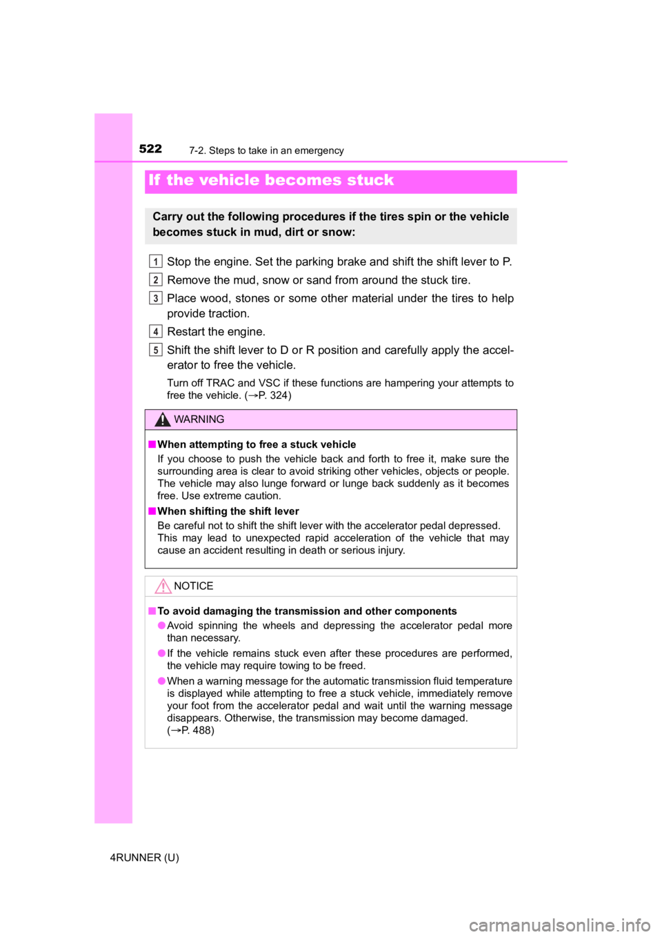
Stop the engine. Set the parking brake and shift the shift lever to P.
Remove the mud, snow or sand from around the stuck tire.
Place wood, stones or some other material under the tires to help
provide traction.
Restart the engine.
Shift the shift lever to D or R position and carefully apply th e accel-
erator to free the vehicle.
Turn off TRAC and VSC if these functions are hampering your attempts to
free the vehicle. ( P. 324)
If the vehicle becomes stuck
Carry out the following procedures if the tires spin or the vehicle
becomes stuck in mud, dirt or snow:
WARNING
■When attempting to f ree a stuck vehicle
If you choose to push the vehicle back and forth to free it, make sure the
surrounding area is clear to avoid striking other vehicles, obj ects or people.
The vehicle may also lunge forward or lunge back suddenly as it becomes
free. Use extreme caution.
■ When shifting the shift lever
Be careful not to shift the shift lever with the accelerator pedal depressed.
This may lead to unexpected rapid acceleration of the vehicle t hat may
cause an accident resulting in death or serious injury.
NOTICE
■ To avoid damaging the transmission and other components
● Avoid spinning the wheels and depressing the accelerator pedal more
than necessary.
● If the vehicle remains stuck even after these procedures are pe rformed,
the vehicle may require towing to be freed.
● When a warning message for the automatic transmission fluid tem perature
is displayed while attempting to free a stuck vehicle, immediat ely remove
your foot from the accelerator pedal and wait until the warning message
disappears. Otherwise, the transmission may become damaged.
(
P. 488)
1
2
3
4
5
Page 531 of 608
5318-1. Specifications
8
Vehicle specifications
4RUNNER (U)
*: The fluid capacity is a reference quantity. If replacement is necessary, con-
tact your Toyota dealer.
*1: Minimum pedal clearance when depressed with a force of 110 lbf (490 N, 50 kgf) while the engine is running.
*2: Parking brake pedal travel when depressed with a force of 67 lbf (300 N,30 kgf).
Automatic transmission
Fluid capacity*11.3 qt. (10.7 L, 9.4 Imp. qt.)
Fluid typeToyota Genuine ATF WS
NOTICE
■ Transmission fluid type
Using transmission fluid other than the above type may cause abnormal
noise or vibration, or damage the transmission of your vehicle.
Brakes
Pedal clearance*1
2WD models
3.36 in. (86 mm) Min.
4WD models
3.54 in. (90 mm) Min.
Pedal free playLess than 0.04 0.24 in. (1 6 mm)
Brake pad wear limit0.04 in. (1.0 mm)
Parking brake lining wear limit0.04 in. (1.0 mm)
Parking brake pedal travel*25 7 clicks
Fluid typeSAE J1703 or FMVSS No.116 DOT 3
Page 543 of 608

5438-1. Specifications
8
Vehicle specifications
4RUNNER (U)
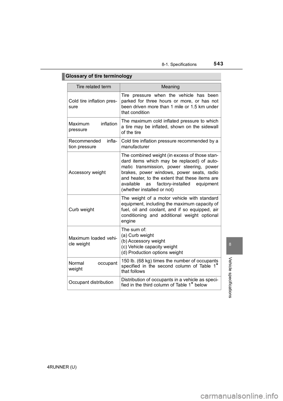
Glossary of tire terminology
Tire related termMeaning
Cold tire inflation pres-
sure
Tire pressure when the vehicle has been
parked for three hours or more, or has not
been driven more than 1 mile or 1.5 km under
that condition
Maximum inflation
pressureThe maximum cold inflated pressure to which
a tire may be inflated, shown on the sidewall
of the tire
Recommended infla-
tion pressureCold tire inflation pressure recommended by a
manufacturer
Accessory weight
The combined weight (in excess of those stan-
dard items which may be replaced) of auto-
matic transmission, power steering, power
brakes, power windows, power seats, radio
and heater, to the extent that these items are
available as factory-installed equipment
(whether installed or not)
Curb weight
The weight of a motor vehicle with standard
equipment, including the maximum capacity of
fuel, oil and coolant, and if so equipped, air
conditioning and additional weight optional
engine
Maximum loaded vehi-
cle weight
The sum of:
(a) Curb weight
(b) Accessory weight
(c) Vehicle capacity weight
(d) Production options weight
Normal occupant
weight150 lb. (68 kg) times the number of occupants
specified in the second column of Table 1
*
that follows
Occupant distributionDistribution of occupants in a vehicle as speci-
fied in the third column of Table 1
* below
Page 544 of 608

5448-1. Specifications
4RUNNER (U)
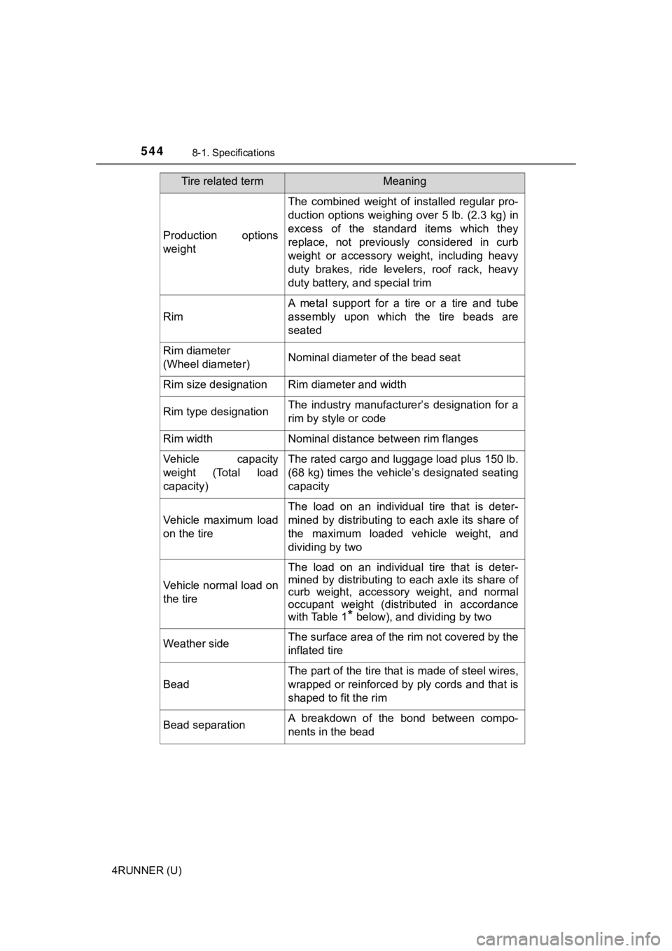
Production options
weight
The combined weight of installed regular pro-
duction options weighing over 5 lb. (2.3 kg) in
excess of the standard items which they
replace, not previously considered in curb
weight or accessory weight, including heavy
duty brakes, ride levelers, roof rack, heavy
duty battery, and special trim
Rim
A metal support for a tire or a tire and tube
assembly upon which the tire beads are
seated
Rim diameter
(Wheel diameter)Nominal diameter of the bead seat
Rim size designationRim diameter and width
Rim type designationThe industry manufacturer’s designation for a
rim by style or code
Rim widthNominal distance between rim flanges
Vehicle capacity
weight (Total load
capacity)The rated cargo and l uggage load plus 150 lb.
(68 kg) times the vehicle’s designated seating
capacity
Vehicle maximum load
on the tire
The load on an individual tire that is deter-
mined by distributing to each axle its share of
the maximum loaded vehicle weight, and
dividing by two
Vehicle normal load on
the tire
The load on an individual tire that is deter-
mined by distributing to each axle its share of
curb weight, accessory weight, and normal
occupant weight (distributed in accordance
with Table 1
* below), and dividing by two
Weather sideThe surface area of the rim not covered by the
inflated tire
Bead
The part of the tire that is made of steel wires,
wrapped or reinforced by ply cords and that is
shaped to fit the rim
Bead separationA breakdown of the bond between compo-
nents in the bead
Tire related termMeaning