2023 SUBARU SOLTERRA change time
[x] Cancel search: change timePage 279 of 628

2795-4. Using the driving support systems
Owners Manual_USA_M42C01_en
5
Driving
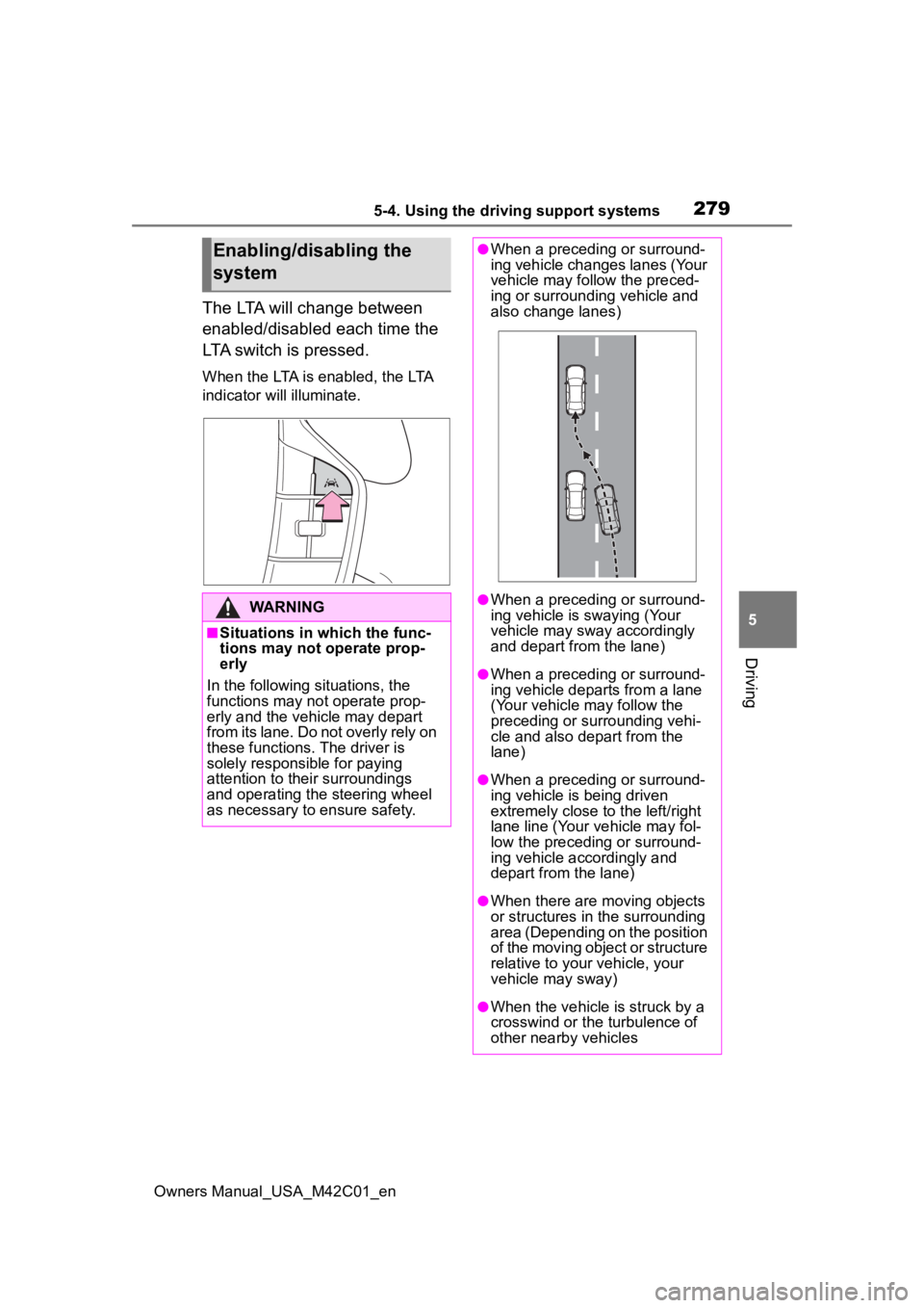
The LTA will change between
enabled/disabled each time the
LTA switch is pressed.
When the LTA is enabled, the LTA
indicator will illuminate.
Enabling/disabling the
system
WARNING
■Situations in which the func-
tions may not operate prop-
erly
In the following situations, the
functions may not operate prop-
erly and the vehicle may depart
from its lane. Do not overly rely on
these functions. The driver is
solely responsible for paying
attention to their surroundings
and operating the steering wheel
as necessary to ensure safety.
●When a preceding or surround-
ing vehicle changes lanes (Your
vehicle may follow the preced-
ing or surrounding vehicle and
also change lanes)
●When a preceding or surround-
ing vehicle is swaying (Your
vehicle may sway accordingly
and depart from the lane)
●When a preceding or surround-
ing vehicle departs from a lane
(Your vehicle may follow the
preceding or surrounding vehi-
cle and also depart from the
lane)
●When a preceding or surround-
ing vehicle is being driven
extremely close to the left/right
lane line (Your vehicle may fol-
low the preceding or surround-
ing vehicle accordingly and
depart from the lane)
●When there are moving objects
or structures in the surrounding
area (Depending on the position
of the moving object or structure
relative to your vehicle, your
vehicle may sway)
●When the vehicle is struck by a
crosswind or the turbulence of
other nearby vehicles
Page 284 of 628

2845-4. Using the driving support systems
Owners Manual_USA_M42C01_en
●When the system determines that
the driver is not securely holding
the steering wheel, or the steering
wheel is not being operated when
the steering assist operation of the
lane departure prevention function
is operating
The length of time that the warning
buzzer operates will become longer
as the frequency o f the steering
assist operating i ncreases. Even if
the system judges that the steering
wheel has been operated, the warn-
ing buzzer will sound for a certain
amount of time.
■Break suggestion function
If the vehicle is swaying, a message
will be displayed and a warning
buzzer will sound to u rge the driver
to take a break.
Depending on the condition of the
vehicle and road surface, the break
suggestion functi on may not oper-
ate.
The LDA system can be
enabled/disabled through a
customize setting. ( P.572)
The settings of the LDA can be changed through on the
customize settings. (
P.572)
Changing LDA settings
WARNING
■Situations in which the LDA
should not be used
In the following situations, disable
the LDA system. Failure to do so
may lead to an accident.
●When it is necessary to disable
the system: P.259
■Situations in which the sys-
tem may not ope rate properly
In the following situations, the
system may not operate properly
and the vehicle may depart from
its lane. Do not overly rely on
these functions. The driver is
solely responsible for paying
attention to their surroundings
and operating the steering wheel
as necessary to ensure safety.
●When the boundary between
the asphalt and grass, soil, etc.,
or structures, such as a curb,
guardrail, etc. is not clear or
straight
●When the vehicle is struck by a
crosswind or the turbulence of
other nearby vehicles
●Situations in which the lane may
not be detected: P.264
●Situations in which the sensors
may not operate properly:
P.263
●Situations in which some or all
of the functions of the system
cannot operate: P.264
Page 286 of 628

2865-4. Using the driving support systems
Owners Manual_USA_M42C01_en
When the front camera
detects a sign or information of a sign is available from the
navigation system (if
equipped), the sign will be
displayed on the display.
Multiple signs can be dis-
played.
Depending on the specifications of
the vehicle, the number of dis-
played signs may be limited.
■Operating conditions of sign
display
Signs will be displayed when the fol-
lowing conditions are met:
●The system has detected a sign
In the following si tuations, a dis-
played sign may stop being dis-
played:
●When a new sign has not been
detected for a certain distance
●When the system determines that
the road being driven on has
changed, such as after a left or
right turn
■Situations in which the display
function may not operate prop-
erly
In the following situ ations, the RSA
system may not operate properly
and may not detect signs or may
display the incorrect sign. However,
this does not indicate a malfunction.
●When a sign is dirty, faded, tilted
or bent
●When the contrast of an electronic
sign is low
●When all or part of a sign is hidden
by a tree, utility pole, etc.
●When a sign is d etected by the
front camera for a short amount of
time
●When the driving state (turning,
changing lanes, etc.) is judged
incorrectly
●When a sign is immediately after a
RSA (Road Sign
Assist)
The RSA system detects
specific road signs using
the front camera and/or
navigation system (if
equipped) (when speed limit
information is available)
and warns the driver via dis-
plays and buzzers.
WARNING
■For safe use
●Driving safely is solely the
responsibility of the driver. Pay
careful attention to the sur-
rounding conditions in order to
ensure safe driving.
●Do not rely solely upon the
RSA. The RSA assists the
driver by providing road sign
information, but it is not a
replacement for the driver’s own
vision and awareness. Driving
safely is solely the responsibility
of the driver. Pay careful atten-
tion to the surrounding condi-
tions in order to ensure safe
driving.
■Situations in which the RSA
should not be used
When it is necessary to disable
the system: P. 2 5 9
■Situations in which the sys-
tem may not operate properly
Situations in which the sensors
may not operate properly: P. 2 6 3
Display Function
Page 290 of 628

2905-4. Using the driving support systems
Owners Manual_USA_M42C01_en
Constant speed cruising:
When there are no vehicles ahead
The vehicle drives at the speed set by the driver.
If the set vehicle speed is exceeded while driving down a hill, the set vehicle
speed display will blin k and a buzzer will sound.
Deceleration and follow-up cruising
When a preceding vehicle driving slower than the set vehicle
speed is detected
When a vehicle is detected driving ahead of your vehicle, the v ehicle auto-
matically decelerates and if a greater reduction in vehicle spe ed is neces-
sary, the brakes are applied (the stop lights will come on at t his time). The
vehicle is controlled to maintai n the vehicle-to-vehicle distance set by the
driver, in accordance with changes in the speed of the precedin g vehicle. If
vehicle deceleration is not sufficient and the vehicle approaches the vehicle
ahead, the approach wa rning will sound.
Acceleration
When there are no longer any preceding vehicles driving slower
than the set vehicle speed
The vehicle accelerates until th e set vehicle speed is reached and then
resumes constant speed cruising.
Starting off: If a preceding vehi cle stops, the vehicle will also stop
(controlled stop). After the preceding vehicle starts off, pressing
the “RES” switch or depressing the accelerator pedal will resum e
follow-up cruising (start off operation). If a start off operat ion is not
performed, the controlled stop will continue.
Basic functions
Page 292 of 628

2925-4. Using the driving support systems
Owners Manual_USA_M42C01_en
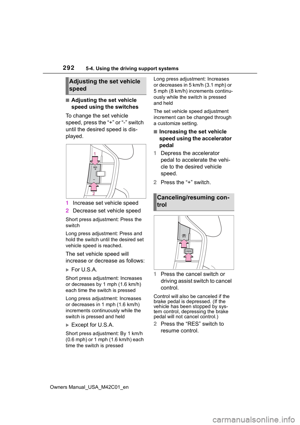
■Adjusting the set vehicle
speed using the switches
To change the set vehicle
speed, press the “+” or “-” switch
until the desired speed is dis-
played.
1 Increase set vehicle speed
2 Decrease set vehicle speed
Short press adjustment: Press the
switch
Long press adjustment: Press and
hold the switch until the desired set
vehicle speed is reached.
The set vehicle speed will
increase or decrease as follows:
For U.S.A.
Short press adjus tment: Increases
or decreases by 1 mph (1.6 km/h)
each time the switch is pressed
Long press adjustment: Increases
or decreases in 1 mph (1.6 km/h)
increments continuously while the
switch is pressed and held
Except for U.S.A.
Short press adjustment: By 1 km/h
(0.6 mph) or 1 mph (1.6 km/h) each
time the switch is pressed Long press adjustment: Increases
or decreases in 5 km/h (3.1 mph) or
5 mph (8 km/h) inc
rements continu-
ously while the switch is pressed
and held
The set vehicle speed adjustment
increment can be changed through
a customize setting.
■Increasing the set vehicle
speed using the accelerator
pedal
1 Depress the accelerator
pedal to accelerate the vehi-
cle to the desired vehicle
speed.
2 Press the “+” switch.
1 Press the cancel switch or
driving assist switch to cancel
control.
Control will also be canceled if the
brake pedal is depressed. (If the
vehicle has been stopped by sys-
tem control, depre ssing the brake
pedal will not cancel control.)
2 Press the “RES” switch to
resume control.
Adjusting the set vehicle
speed
Canceling/resuming con-
trol
Page 293 of 628

2935-4. Using the driving support systems
Owners Manual_USA_M42C01_en
5
Driving
Each time the switch is pressed,
the vehicle-to-vehicle distance
setting will change as follows:
If a preceding vehicle is detected,
the preceding vehicle mark will
be displayed.
The actual vehicle-to-vehicle dis-
tance varies in accordance with the
vehicle speed. Also, when the vehi-
cle is stopped by system control, it
will be stopped at a certain distance
from the preceding vehicle,
depending on the situation, regard-
less of the setting.
■Operating conditions
●D shift position is selected.
●The desired set speed can be set
when the vehicle speed is approx-
imately 20 mph (30 km/h) or more.
(If the vehicle speed is set while
driving at below approximately 20
mph [30 km/h], th e set speed will
be set to approxi mately 20 mph
[30 km/h].)
■Accelerating after setting the
vehicle speed
As with normal driving, acceleration
can be performed by depressing the
accelerator pedal. After accelerat-
ing, the vehicle will return to the set
vehicle speed. However, while in
vehicle-to-vehicle distance control
mode, the vehicle speed may
decrease to below the set vehicle
speed in order to maintain the dis-
tance from the preceding vehicle.
■When the vehicle is stopped by
system control during follow-up
cruising
●When the “RES” switch is pressed
while the vehicle is stopped by
system control, if the preceding
vehicle starts off within approxi-
mately 3 seconds, follow-up cruis-
ing will resume.
●If the preceding vehicle starts off
within approximately 3 seconds of
the vehicle being stopped by sys-
tem control, follo w-up cruising will
resume.
■Automatic cancelation of vehi-
cle-to-vehicle d istance control
mode
In the following situ ations, vehicle-
to-vehicle distance control mode will
be canceled automatically:
●When the brake control or output
restriction control of a driving sup-
port system oper ates (For exam-
ple: Pre-Collision System, drive-
start control)
●When the parking brake has been
Changing the vehicle-to-
vehicle distance
Illustra-
tion
NumberVehicle- to-vehi-
cle dis- tanceApproximate
Distance (Vehi-
cle Speed: 60
mph [100 km/h])
1Extra longApproximately 200 ft. (60 m)
2LongApproximately 145 ft. (45 m)
3MediumApproximately 100 ft. (30 m)
4ShortApproximately 85 ft. (25 m)
Page 298 of 628

2985-4. Using the driving support systems
Owners Manual_USA_M42C01_en
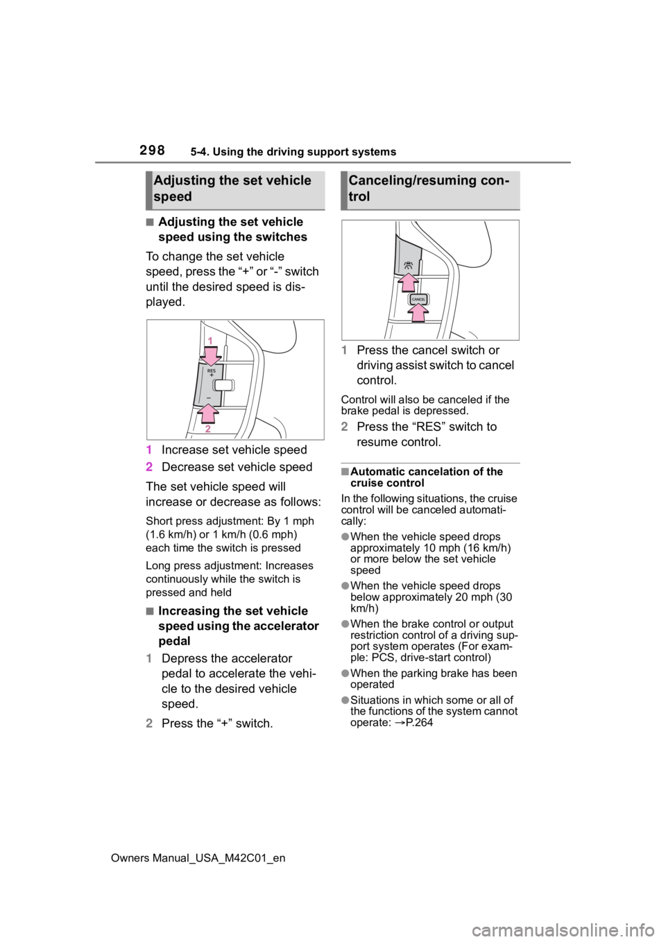
■Adjusting the set vehicle
speed using the switches
To change the set vehicle
speed, press the “+” or “-” switch
until the desired speed is dis-
played.
1 Increase set vehicle speed
2 Decrease set vehicle speed
The set vehicle speed will
increase or decrease as follows:
Short press adjustment: By 1 mph
(1.6 km/h) or 1 km/h (0.6 mph)
each time the switch is pressed
Long press adjustment: Increases
continuously while the switch is
pressed and held
■Increasing the set vehicle
speed using the accelerator
pedal
1 Depress the accelerator
pedal to accelerate the vehi-
cle to the desired vehicle
speed.
2 Press the “+” switch. 1
Press the cancel switch or
driving assist switch to cancel
control.
Control will also be canceled if the
brake pedal is depressed.
2Press the “RES” switch to
resume control.
■Automatic cancelation of the
cruise control
In the following situations, the cruise
control will be canceled automati-
cally:
●When the vehicle speed drops
approximately 10 mph (16 km/h)
or more below the set vehicle
speed
●When the vehicle speed drops
below approximately 20 mph (30
km/h)
●When the brake control or output
restriction control of a driving sup-
port system oper ates (For exam-
ple: PCS, drive-start control)
●When the parking brake has been
operated
●Situations in which some or all of
the functions of the system cannot
operate: P. 2 6 4
Adjusting the set vehicle
speedCanceling/resuming con-
trol
Page 302 of 628

3025-4. Using the driving support systems
Owners Manual_USA_M42C01_en
*: If equipped
Meter control switches
Turning the Blind Spot Monitor
on/off.
Outside rear view mirror indi-
cators
When a vehicle is detected in a
blind spot of the outside rear view
mirrors or approaching rapidly from
behind into a blind spot, the outside
rear view mirror indicator on the
detected side will illuminate. If the
turn signal lever is operated toward
the detected side, the outside rear
view mirror indicator flashes.
Driving assist information
indicator
Illuminates when the Blind Spot
Monitor is turned off. At this time,
“Blind Spot Monitor OFF” will be
displayed on the multi-information
display.
■Outside rear view mirror indica-
tor visibility
In strong sunlight, the outside rear
view mirror indicator may be difficult
to see.
■Customization
Some functions can be customized.
( P.573)
BSM (Blind Spot Moni-
tor)*
The Blind Spot Monitor is a
system that uses rear side
radar sensors installed on
the inner side of the rear
bumper on the left and right
side to assist the driver in
confirming safety when
changing lanes.
WARNING
■Cautions regarding the use of
the system
●The driver is solely responsible
for safe driving. Always drive
safely, taking care to observe
your surroundings.
●The Blind Spot Monitor is a sup-
plementary function which alerts
the driver that a vehicle is in a
blind spot of the outside rear
view mirrors or is approaching
rapidly from behind into a blind
spot. Do not overly rely on the
Blind Spot Monitor. As the func-
tion cannot judge if it is safe to
change lanes, over reliance
could lead to an accident result-
ing in death or serious injury.
As the system may not function
correctly under certain condi-
tions, the driver’s own visual con-
firmation of safety is necessary.
System components