2023 RAM PROMASTER aux 1 switch
[x] Cancel search: aux 1 switchPage 5 of 296

3
INTERIOR STORAGE AND EQUIPMENT ............... 44 Storage..............................................................44
USB Control — If Equipped ..............................45
Power Outlets ...................................................46
Power Inverter — If Equipped...........................47
Auxiliary Switches — If Equipped .....................47
Wireless Charging Pad —
If Equipped .......................................................48
WINDOWS ............................................................. 49
Power Windows ...............................................49
Window Bar Grates — If Equipped...................49
Wind Buffeting .................................................50
HOOD....................................................................... 50
Opening .............................................................50
Closing...............................................................51
CARGO AREA FEATURES ...................................... 51
GETTING TO KNOW YOUR
INSTRUMENT PANEL
BASE / MIDLINE INSTRUMENT CLUSTER........... 52
Base / Midline Instrument Cluster
Descriptions ......................................................53
INSTRUMENT CLUSTER......................................... 54
Instrument Cluster Descriptions .....................55
INSTRUMENT CLUSTER DISPLAY ........................ 56
Location And Controls ......................................56
Change Engine Oil — If Equipped ....................57
Main Menu........................................................57
Settings .............................................................59 WARNING LIGHTS AND MESSAGES ....................65
Red Warning Lights ..........................................65
Yellow Warning Lights ......................................68
Yellow Indicator Lights .....................................72
Green Indicator Lights .....................................72
Blue Indicator Lights ........................................73
White Indicator Lights ......................................73
ONBOARD DIAGNOSTIC SYSTEM — OBD II ........ 74
Onboard Diagnostic System
(OBD II) Cybersecurity ......................................74
EMISSIONS INSPECTION AND MAINTENANCE
PROGRAMS.............................................................74
STARTING AND OPERATING
STARTING THE ENGINE ........................................76
Automatic Transmission ..................................76
Normal Starting ................................................76
Tip Start Feature .............................................76
Cold Weather Operation
(Below –22°F Or −30°C) ...............................76
Extended Park Starting ....................................76
If Engine Fails To Start .....................................77
After Starting ....................................................77
ENGINE BLOCK HEATER — IF EQUIPPED ...........77
ENGINE BREAK-IN RECOMMENDATIONS ..........78
PARKING BRAKE ....................................................78
Electric Park Brake (EPB) ................................78 AUTOMATIC TRANSMISSION .............................. 81
Ignition Park Interlock (Keyless Vehicle) ........ 81
Brake/Transmission Shift Interlock (BTSI)
System ............................................................. 81
9-Speed Automatic Transmission ................... 82
POWER STEERING ................................................ 85
ACTIVE SPEED LIMITER — IF EQUIPPED ............ 86
Activation .......................................................... 86
Exceeding The Set Speed ................................ 86
Deactivation ..................................................... 86
INTELLIGENT SPEED ASSIST (ISA) —
IF EQUIPPED ........................................................... 87
Activation .......................................................... 87
Exceeding The Set Speed ................................ 87
Deactivation ..................................................... 87
CRUISE CONTROL SYSTEMS — IF EQUIPPED ... 87
Cruise Control .................................................. 88
Adaptive Cruise Control (ACC) ......................... 89
TRAFFIC SIGN ASSIST SYSTEM —
IF EQUIPPED ........................................................... 98
Activation/Deactivation ................................... 98
Traffic Sign Assist Modes ................................ 98
Indications On The Display .............................. 99
ACTIVE DRIVING ASSIST SYSTEM —
IF EQUIPPED ......................................................... 100
Operation ....................................................... 100Turning Active Driving Assist
On Or Off ........................................................ 101
23_VF_OM_EN_USC_t.book Page 3
Page 49 of 296

GETTING TO KNOW YOUR VEHICLE47
POWER INVERTER — IF EQUIPPED
There is a 115 Volt, 150 Watt inverter outlet
located on the instrument panel, to the right of
the radio, to convert DC current to AC current.
This outlet can power cellular phones, electronics
and other low power devices requiring power up to
150 Watts. Certain game consoles will exceed this
power limit, as will most power tools.
Power Inverter Location
To turn on the power inverter outlet, simply plug in
the device. The outlet automatically turns off when
the device is unplugged.
The power inverter is designed with built-in overload
protection. If the power rating of 150 Watts is
exceeded, the power inverter will automatically shut
down. Once the electrical device has been removed
from the outlet the inverter should automatically reset.
To avoid overloading the circuit, check the power
ratings on electrical devices prior to using the inverter.
AUXILIARY SWITCHES — IF EQUIPPED
Your vehicle may be equipped with two auxiliary
switches located on the instrument panel to the
left of the steering column which can be used to
power various electronic devices. Connections to
the switches are found in the right central pillar
fuse panel at the base of the passenger side
B-pillar.
Auxiliary Switches
Auxiliary Switch 1 is configured to constant battery
feed, while Auxiliary Switch 2 is configured to
ignition feed.
For further information on using the auxiliary
switches, please refer to the Ram Body Builder’s
Guide by accessing
www.rambodybuilder.com
and choosing the appropriate links.
After the use of high power draw accessories, or
long periods of the vehicle not being started (with
accessories still plugged in), the vehicle must be
driven a sufficient length of time to allow the
generator to recharge the vehicle's battery.
CAUTION!
WARNING!
To avoid serious injury or death:
Do not insert any objects into the receptacles.
Do not touch with wet hands.
Close the lid when not in use.
If this outlet is mishandled, it may cause an
electric shock and failure.
2
23_VF_OM_EN_USC_t.book Page 47
Page 245 of 296

SERVICING AND MAINTENANCE243
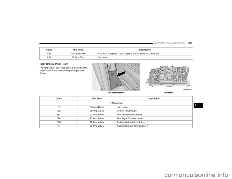
Right Central Pillar Fuses
The right central pillar fuse panel is located on the
interior side at the base of the passenger side
B-pillar.
Fuse Panel LocationFuse Panel
F53
7.5 Amp Brown +30 (IPC) + Keyless – GO / Passive Entry / Brake NO / EPB SW
F94 15 Amp Blue Not Used
CavityMini Fuse Description
CavityMini Fuse Description
* If Equipped
F81 7.5 Amp BrownSeat Heater
F82 30 Amp GreenInverter Power Outlet
F83 20 Amp YellowRear Left Windows Heater
F84 20 Amp YellowRear Right Windows Heater
F86 20 Amp YellowAuxiliary Switch (From Battery) *
F87 20 Amp YellowAuxiliary Switch (From Ignition) *8
23_VF_OM_EN_USC_t.book Page 243