2023 PEUGEOT 308 change wheel
[x] Cancel search: change wheelPage 137 of 260

135
Driving
6– The ignition has been switched off for a few
minutes.
–
The driver's seat belt is unfastened and their
door is opened.
As soon as the speed of the vehicle drops below 43 mph (70 km/h), the
system goes into standby.
Driving time starts being counted again once
the speed reaches above 43
mph (70 km/h).
Driver Attention Warning by
Camera
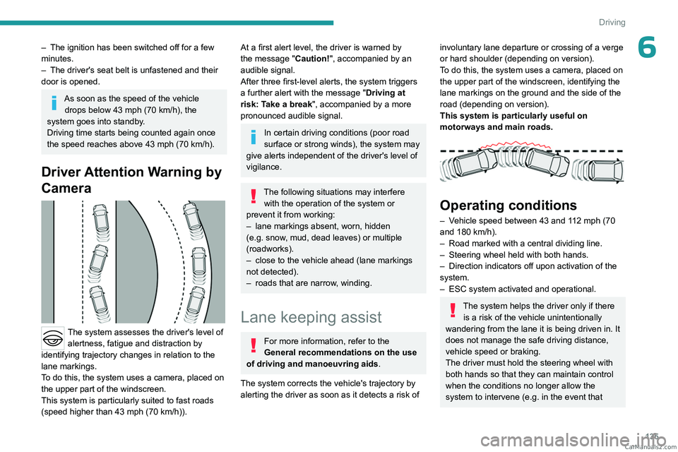
The system assesses the driver's level of alertness, fatigue and distraction by
identifying trajectory changes in relation to the
lane markings.
To do this, the system uses a camera, placed on
the upper part of the windscreen.
This system is particularly suited to fast roads
(speed higher than 43 mph (70
km/h)).
At a first alert level, the driver is warned by
the message "Caution!", accompanied by an
audible signal.
After three first-level alerts, the system triggers
a further alert with the message " Driving at
risk: Take a break", accompanied by a more
pronounced audible signal.
In certain driving conditions (poor road
surface or strong winds), the system may
give alerts independent of the driver's level of
vigilance.
The following situations may interfere with the operation of the system or
prevent it from working:
–
lane markings absent, worn, hidden
(e.g.
snow, mud, dead leaves) or multiple
(roadworks).
–
close to the vehicle ahead (lane markings
not detected).
–
roads that are narrow
, winding.
Lane keeping assist
For more information, refer to the
General recommendations on the use
of driving and manoeuvring aids .
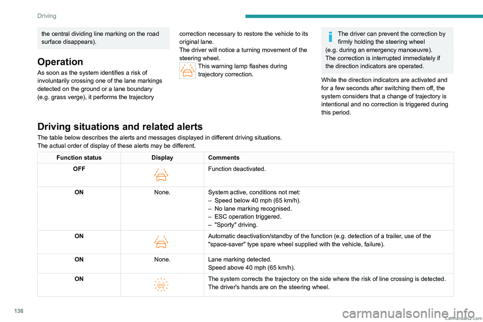
The system corrects the vehicle's trajectory by
alerting the driver as soon as it detects a risk of
involuntary lane departure or crossing of a verge
or hard shoulder (depending on version).
To do this, the system uses a camera, placed on
the upper part of the windscreen, identifying the
lane markings on the ground and the side of the
road (depending on version).
This system is particularly useful on
motorways and main roads.
Operating conditions
– Vehicle speed between 43 and 112 mph (70
and 180 km/h).
–
Road marked with a central dividing line.
–
Steering wheel held with both hands.
–
Direction indicators off upon activation of the
system.
–
ESC system activated and operational.
The system helps the driver only if there is a risk of the vehicle unintentionally
wandering from the lane it is being driven in. It
does not manage the safe driving distance,
vehicle speed or braking.
The driver must hold the steering wheel with
both hands so that they can maintain control
when
the conditions no longer allow the
system to intervene (e.g.
in the event that CarM an uals 2 .c o m
Page 138 of 260

136
Driving
the central dividing line marking on the road
surface disappears).
Operation
As soon as the system identifies a risk of
involuntarily crossing one of the lane markings
detected on the ground or a lane boundary
(e.g. grass verge), it performs the trajectory correction necessary to restore the vehicle to its
original lane.
The driver will notice a turning movement of the
steering wheel.This warning lamp flashes during
trajectory correction.
The driver can prevent the correction by firmly holding the steering wheel
(e.g.
during an emergency manoeuvre).
The correction is interrupted immediately if
the direction indicators are operated.
While the direction indicators are activated and
for a few seconds after switching them off, the
system considers that a change of trajectory is
intentional and no correction is triggered during
this period.
Driving situations and related alerts
The table below describes the alerts and messages displayed in different driving situations.
The actual order of display of these alerts may be different.
Function status DisplayComments
OFF
Function deactivated.
ON None.System active, conditions not met:
–
Speed below 40 mph (65
km/h).
–
No lane marking recognised.
–
ESC operation triggered.
–
"Sporty" driving.
ON
Automatic deactivation/standby of the function (e.g. detection of a trailer, use of the
"space-saver" type spare wheel supplied with the vehicle, failure).
ON None.Lane marking detected.
Speed above 40 mph (65
km/h).
ON
The system corrects the trajectory on the side where the risk of line cr\
ossing is detected.
The driver's hands are on the steering wheel. CarM an uals 2 .c o m
Page 141 of 260

139
Driving
6The system may be temporarily disturbed by certain weather conditions (e.g. heavy
rain, hail or extreme temperature changes).
In particular, driving on a wet road or going
from a dry to a wet area can cause false
alerts (e.g.
presence of a cloud of water
droplets in the blind spot interpreted as a
vehicle).
In bad or wintry weather, ensure that
the
radars are not covered by mud, ice or
snow.
Take care not to cover the warning zone in
the door mirrors, or the detection zones on
the rear bumper, with adhesive labels or
other objects; they may hamper the correct
operation of the system.
Parking sensors
For more information, refer to the
General recommendations on the use
of driving and manoeuvring aids .
This system detects and signals the proximity of
obstacles (e.g.
pedestrian, vehicle, tree, barrier)
using sensors located in the bumper.
Rear parking sensors
► Engage reverse gear to start the system
(confirmed by an audible signal).
The system is switched off when reverse gear is
disengaged.
Audible assistance
The system signals the presence of obstacles
which are both within the sensors’ detection zone
and in the vehicle path defined by the direction of
the steering wheel.
Depending on version, in the example shown,
only the obstacles present in the shaded area
will be signalled by the audible assistance.
The proximity information is given by an
intermittent audible signal, the frequency of
which increases as the vehicle approaches the
obstacle.
When the distance between the vehicle and
the obstacle becomes less than about thirty
centimetres, the audible signal becomes
continuous.
The sound emitted by the speaker (right or
left) indicates the side on which the obstacle is
located.
Adjusting the audible signalPressing this button opens the
window for adjusting the volume
of the audible signal.
Visual assistance
This supplements the audible signal, without
taking account of the vehicle's trajectory, by
displaying bars on the screen whose location
represents the distance between the obstacle
and the vehicle (white: more distant, orange:
close, red: very close). CarM an uals 2 .c o m
Page 144 of 260

142
Driving
Standard view
The area behind the vehicle is displayed on the
screen.
The blue lines 1 represent the width of your
vehicle, with the mirrors unfolded; their direction
changes according to the position of the steering
wheel.
The red line 2 represents a distance of 30
cm
from the rear bumper; the two blue lines 3 and 4
represent 1
m and 2 m, respectively.
This view is available automatically or by
selection in the side menu.
Panoramic view
The panoramic view allows you to leave, in
reverse, a parking space by anticipating the
arrival of vehicles, pedestrians or cyclists.
This view is not recommended for carrying out a
complete manoeuvre.
This view is only available by selection in the
side menu.
Visiopark 3
For more information, refer to the
General recommendations on the use
of driving and manoeuvring aids .
This system allows you to view your vehicle's
close surroundings
on the touch screen using
cameras, located at the front and rear of the
vehicle, as well as under the door mirrors.
The screen is divided into 4 parts with two side
menus, a contextual view and a view from above
the vehicle in its close surroundings.
The parking sensors supplement the information
in the view from above the vehicle.
Depending on the view angle chosen in the
left-hand side menu, the system provides
specific visual assistance in particular driving
conditions, such as entering a blind intersection
or manoeuvring in areas with reduced visibility. Different contextual views are available for the
rear or for the front:
–
Automatic zoom view
.
–
Standard view
.
–
Panoramic view
.
Depending on the context, the system chooses
the best view to display (standard or automatic
zoom).
The view type can be changed at any time
during the manoeuvre.
The system status is not saved when the ignition
is switched off.
Operating principle
Reconstructed view
The cameras are activated and a reconstruction
of a view from above your vehicle in its close
surroundings is displayed on the touch screen.
Live view
The front, rear and side views automatically
appear in the view from above the vehicle.
It is also possible to display any live view by
selecting the corresponding zone.
The front view can be selected in forward gear
up to 10 mph (16 km/h). CarM an uals 2 .c o m
Page 145 of 260

143
Driving
6Installing the very cold climate screen
can alter the image transmitted by the
front camera.
An additional jet is fitted above the number plate to clean the reversing camera (depending on
version).
►
The washing of the reversing camera is
triggered by operating the rear screenwash.
Settings
In the side menu, this menu allows you to
carry out the following operations:
–
adjust the volume of the audible signal.
–
adjust the brightness.
–
adjust the contrast.
Activation/Deactivation
Automatic
With the rear camera, engine running and
vehicle stationary, rear vision is displayed
automatically if reverse gear is engaged.
With the front camera, engine running and speed
below 10 mph (16 km/h), rear vision is displayed
automatically if a gear is engaged.
Manual
► In the ADAS touch screen application,
select Functions>Panoramic Camera
The system is deactivated:
–
automatically for the rear
, when changing out
of reverse gear.
– automatically for the front, above
approximately 10 mph (16 km/h).
–
by pressing the cross in the top left-hand
corner of the touch screen.
Automatic zoom view
The front or rear camera records the
surroundings during the manoeuvre to create
a front or rear view from above the vehicle in
its close surroundings, making it possible to
manoeuvre the vehicle around the surrounding
obstacles.
Using the sensors located on the front or
rear
bumper, the automatic zoom view is
displayed when approaching an obstacle at the
red line (less than 30 cm) during the manoeuvre.
This view is only available automatically.
Depending on version, it can be activated/
deactivated in the ADAS application of the touch
screen.
Obstacles may appear further away than
they actually are.
It is important to monitor the sides of the
vehicle during the manoeuvre, using the
mirrors.
Parking sensors also provide additional
information about the area around the vehicle.
Standard view
Depending on the context, the area behind or in
front of your vehicle is displayed on the screen.
The blue lines (at the rear)/orange lines (at the
front) 1 represent the width of your vehicle, with
the mirrors unfolded;
their direction changes
according to the position of the steering wheel.
The red line 2 represents a distance of 30 cm
from the rear or front bumper; the two blue lines
(at the rear)/orange lines (at the front)
3
and
4
represent 1 m and 2 m respectively.
This view is available automatically or by
selection in the left-hand side menu.
Panoramic view
CarM an uals 2 .c o m
Page 179 of 260

177
In the event of a breakdown
8
Hatchback
SW
Versions with rigid boot floor
► Open the boot.
► Lift the rigid boot floor .
►
Attach the floor hook to the upper boot seal.
Versions with hinged boot carpet
(Rechargeable hybrid)
► Open the boot.
► Unfold the hinged boot carpet by pulling its
handle until it is fully opened.
Versions with 2-position boot floor (SW)
Tools can also be accessed from the row 2
seats, by tilting the backrest of the rear bench
seat.
►
Open the boot.
►
Lift the cover using the cord at the back of
the boot.
or
►
Place the adjustable boot floor in the high
position.
►
Lift the adjustable boot floor and engage it in
the inclined position in the lateral stops to secure
it in this position.
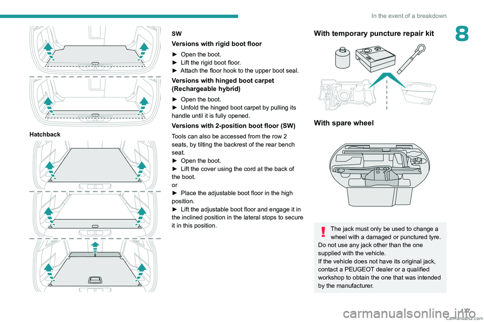
With temporary puncture repair kit
With spare wheel
The jack must only be used to change a wheel with a damaged or punctured tyre.
Do not use any jack other than the one
supplied with the vehicle.
If the vehicle does not have its original jack,
contact a PEUGEOT dealer or a qualified
workshop to obtain the one that was intended
by the manufacturer. CarM an uals 2 .c o m
Page 184 of 260

182
In the event of a breakdown
Hatchback
SW
► T ighten the central nut sufficiently to retain
the wheel correctly.
►
Put the tool box back in place in the middle of
the wheel and clip it in place.
Removing a wheel
Parking the vehicle
Immobilise the vehicle where it does
not obstruct traffic: the ground must be level,
stable and non-slippery.
With a manual gearbox, engage first gear
to lock the wheels, apply the parking brake,
unless it is set to automatic mode, and switch
off the ignition.
With an automatic gearbox, select mode
P
to lock the wheels, apply the parking brake,
unless it is set to automatic mode, and switch
off the ignition.
Check that the parking brake indicator lamps
on the instrument panel are on fixed.
The occupants must get out of the vehicle
and wait where they are safe.
If necessary, place a chock under the wheel
diagonally opposite the wheel to be changed.
Never go underneath a vehicle raised using a
jack; use an axle stand.
Wheel with wheel trim
When removing the wheel , first remove
the wheel trim by pulling at the valve aperture
using the wheelbrace.
When refitting the wheel , refit the wheel
trim, starting by placing its aperture in line
with the valve and then pushing it into place
all round its edge with the palm of your hand.
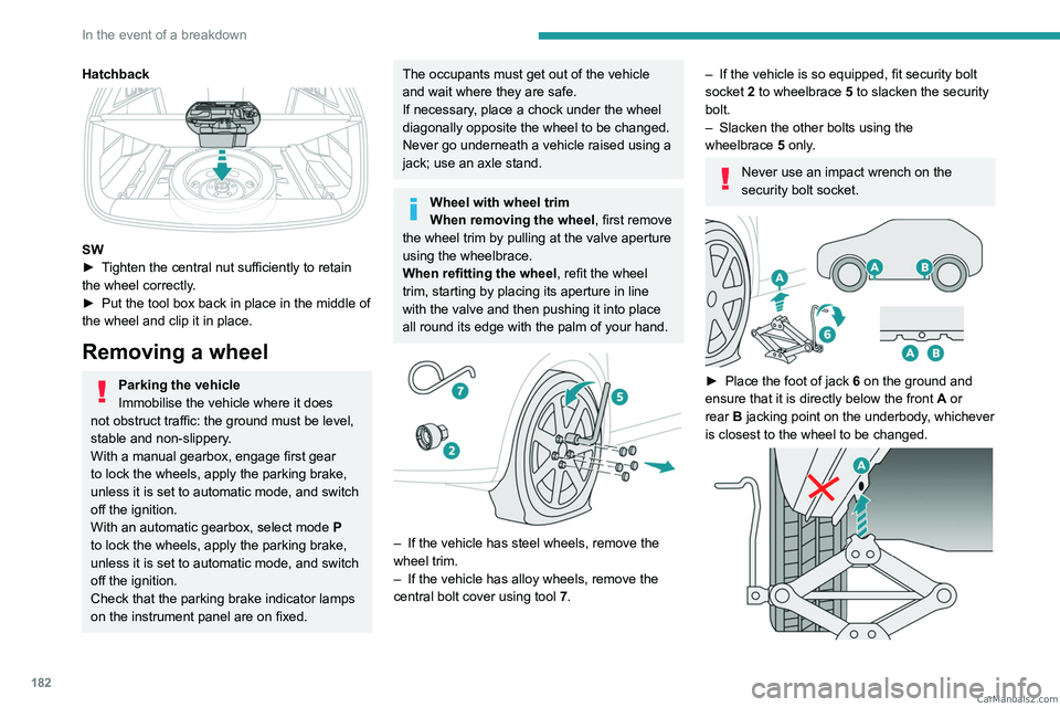
– If the vehicle has steel wheels, remove the
wheel trim.
–
If the vehicle has alloy wheels, remove the
central bolt cover using tool 7
.
– If the vehicle is so equipped, fit security bolt
socket 2 to wheelbrace 5 to slacken the security
bolt.
–
Slacken the other bolts using the
wheelbrace
5
only.
Never use an impact wrench on the
security bolt socket.
► Place the foot of jack 6 on the ground and
ensure that it is directly below the front A or
rear
B jacking point on the underbody, whichever
is closest to the wheel to be changed.
CarM an uals 2 .c o m
Page 219 of 260

217
Vehicle data recording and privacy
11Vehicle data recording
and privacy
Electronic control units are installed in your
vehicle. These control units process data
received from the vehicle's sensors, for example,
or data they generate themselves or exchange
with each other. Some of these control units are
required for the correct operation of your vehicle,
some others assist you while driving (driving or
manoeuvring aids), while others provide comfort
or infotainment functions.
The following contains general information about
how data is processed within the vehicle.
You will find additional information about the
specific data which is downloaded, stored
and transmitted to third parties and what it is
used for in your vehicle under the keyword
"Data protection". This information is directly
associated with the references for the functions
in question contained in the corresponding
vehicle handbook, or in the general terms and
conditions of sale.
This information is also available online.
Vehicle operating data
The control units process the data used for the
operation of the vehicle.
This data includes, for example:
–
Information about the state of the vehicle
(e.g.
speed, travel time, lateral acceleration,
wheel rotation rate, fastened seat belts display). –
Environmental conditions (e.g.
temperature,
rain sensor, distance sensor).
As a general rule, this data is temporary, is
not stored for longer than one operating cycle
and is only used within the vehicle itself. The
control units often record this data (including the
vehicle's key). This function allows either the
temporary or permanent storage of information
about the state of the vehicle, stresses on
components, servicing requirements, as well as
events and technical errors.
Depending on the vehicle's equipment level, the
data stored is as follows:
–
Operating state of system components
(e.g.
filling level, tyre pressures, battery charge
status).
–
Faults and malfunctions in important system
components (e.g.
lamps, brakes).
–
System reactions in specific driving situations
(e.g.
deployment of an airbag, triggering of
stability control and braking systems).
–
Information about events which have
damaged the vehicle.
–
For electric and rechargeable hybrid vehicles,
the traction battery charge level and the
estimated driving range.
In particular circumstances (e.g.
if the vehicle
has detected a malfunction), it may be necessary
to record data which would otherwise simply not
be stored.
When taking your vehicle in for servicing
(e.g.
repairs, maintenance), the stored operating
data may be read along with the vehicle's identification number and used if necessary.
The personnel working for the servicing network
(e.g.
garages, manufacturers) or third parties
(e.g. roadside assistance agents) may read
the vehicle's data. This also applies to work
carried out under warranty and quality assurance
measures.
This data is generally read via the OBD
(On-Board Diagnostics) port fitted by law to
the vehicle. It is used to report on the technical
state of the vehicle or its components and
facilitates the diagnosis of malfunctions, in
compliance with warranty obligations and for
quality improvement. This data, in particular the
information relating to stress on components,
technical events, operator errors and other
malfunctions, is sent to the Manufacturer, if
necessary, along with the vehicle's identification
number. The Manufacturer's liability may also be
engaged. The Manufacturer may also use the
operating data taken from the vehicle for product
recalls. This data may also be used to check the
customer's warranty and any claims made under
warranty.
Any malfunctions stored in the vehicle may be
reset by an after-sales service company during
servicing or repair work, or at your request. CarM an uals 2 .c o m