2023 NISSAN QASHQAI ECO mode
[x] Cancel search: ECO modePage 123 of 508

been driven since the time the ignition
switch was placed in the ON position. (The
elapsed time is also reset at the same
time.)
The elapsed time and trip odometer 2 is
automatically reset each time the ignition
is placed in the OFF position.
Resetting is done by pushing the OK
button. When the OKbutton is pushed,
the following menu items are displayed.
. Cancel
— Return to the previous screen with-
out resetting.
. Distance
— Reset the elapsed time and trip
odometer.
. All
— Reset all items of “Average Speed”,
“Elapsed time and trip odometer”
and “Fuel economy.”
Once the “Elapsed time and trip odometer
1” is displayed, you can use
buttons
to switch between the “Elapsed time and
trip odometer 1” and “Elapsed time and
trip odometer 2.”
4-5. Fuel economy/ECO pedal
guide
Current fuel consumption:
The current fuel consumption mode
shows the current fuel consumption.
Average fuel consumption:
The average fuel consumption 1 mode
shows the average fuel consumption
since the last reset. The average fuel
consumption 2 mode shows the average
fuel consumption since the time the
ignition switch was placed in the ON
position. The average fuel consumption
2 is automatically reset each time the
ignition is placed in the OFF position.
Resetting is done by pushing the OK
button. When the OKbutton is pushed,
the following menu items are displayed.
. Cancel
— Return to the previous screen with-
out resetting.
. Fuel Economy
— Reset the fuel economy.
. All
— Reset all items of “Average Speed”,
“Elapsed time and trip odometer”
and “Fuel economy”.
Once the “Fuel economy 1” is displayed,
you can use
buttons to switch
between the “Fuel economy 1” and “Fuel economy 2”.
The display is updated every 30 seconds.
For about the first 1/3 mile (500 m) after a
reset, the display shows “——”.
6. Audio
The audio mode shows the status of
audio information.
7. Navigation (if so equipped)
When the route guidance is set in the
navigation system, this item shows the
navigation route information.
8. Compass (if so equipped)
This display indicates the heading direc-
tion of the vehicle.
9. Intelligent 4x4 torque distribution
display (if so equipped)
When the Intelligent 4x4 torque distribu-
tion display is selected, you can view the
distribution ratio of the transmission
torque to the front and rear wheels
during driving.
Instruments and controls2-41
Page 124 of 508
2-42Instruments and controls
10. Chassis control
When Intelligent Trace Control, Intelligent
Engine Brake (Continuously Variable
Transmission (CVT) models) or Active Ride
Control system is operated, it shows the
operating condition. It also shows oper-
ating condition of Hill Start Assist. The
operating condition of the automatic
brake hold function (if so equipped) is
also shown. See “Intelligent Trace Control”
(P.5-133), “Intelligent Engine Brake (Con-
tinuously Variable Transmission (CVT)
models)” (P.5-134), “Active Ride Control”
(P.5-135), “Hill Start Assist system” (P.5-136)
or “Automatic brake hold” (P.5-29) for
more details.
11. Tire Pressures
The tire pressure mode shows the pres-
sure of all four tires while the vehicle is
driven.
When the Tire Pressure Low — Add Air
warning appears, the display can be
switched to the tire pressure mode by
pushing the OK
button to reveal addi-
tional details on the displayed warning.
12. Intelligent Driver Alertness (I-DA)
system (if so equipped)
When the “Driver Attention” display is
selected, you can view your attention
level as detected by the system. (See
“Intelligent Driver Alertness (I-DA)” (P.5-
94).)
13. Traffic Sign Recognition (if so
equipped)
The Traffic Sign Recognition (TSR) system
provides the driver with information
about the most recently detected speed
limit. See “Traffic Sign Recognition” (P.2-
43) for more details.
JVI0932X
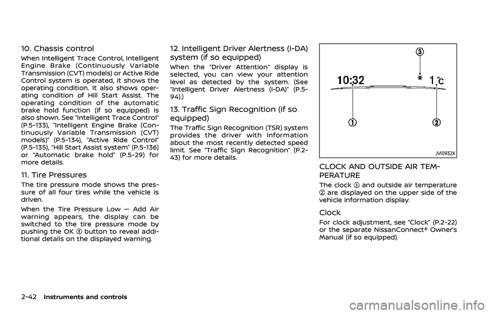
CLOCK AND OUTSIDE AIR TEM-
PERATURE
The clockand outside air temperatureare displayed on the upper side of the
vehicle information display.
Clock
For clock adjustment, see “Clock” (P.2-22)
or the separate NissanConnect® Owner’s
Manual (if so equipped).
Page 125 of 508

Outside air temperature (°F or °C)
The outside air temperature is displayed
in °F or °C in the range of −40 to 140°F (−40
to 60°C).
The outside air temperature mode in-
cludes a low temperature warning fea-
ture. If the outside air temperature is
below 37°F (3°C), the warning
is dis-
played (if so equipped).
The outside temperature sensor is lo-
cated in front of the radiator. The sensor
may be affected by road or engine heat,
wind directions and other driving condi-
tions. The display may differ from the
actual outside temperature or the tem-
perature displayed on various signs or
billboards.
WAC0198X
TRAFFIC SIGN RECOGNITION (if so
equipped)
The Traffic Sign Recognition (TSR) system
provides the driver with information
about the most recently detected speed
limit. The system captures the road sign
information with the multi-sensing front
camera unit
located on the windshield
in front of the inside rearview mirror and
displays the detected signs in the vehicle
information display. For vehicles
equipped with Navigation System, the
speed limit displayed is based on a
combination of Navigation System data
and live camera recognition. TSR informa-
tion is always displayed at the top of the vehicle information display, and option-
ally in the main central area of the display
screen.
WARNING
The TSR system is only intended to
be a support device to provide the
driver with information. It is not a
replacement for the driver’s atten-
tion to traffic conditions or respon-
sibility to drive safely. It cannot
prevent accidents due to careless-
ness. It is the driver’s responsibility
to stay alert and drive safely at all
times.
System operation
The traffic recognition system displays
the following types of road sign:
Instruments and controls2-43
Page 146 of 508
2-64Instruments and controls
When the Rear Door Alert system is
activated and a driver exits the vehicle
after arriving at a destination:
.When the driver puts the vehicle in the
P (Park) position, a message appears
in the vehicle information display for
the driver to “Dismiss Message” or
“Disable Alert” if desired.
. With the system enabled, when the
driver exits the vehicle, an audible alert
(horn sound) will occur unless a rear
door is opened and closed within a
short time to deactivate the alert.
. If the doors are locked before the alert
is deactivated by opening a rear door,
the horn will sound.
. If the system is activated but the
liftgate is opened before opening a
rear door, the horn will be delayed
until after the liftgate is closed.
. If the audible horn alert occurs, a
message will also appear in the vehi-
cle information display that states,
“Check Back Seat for all articles”. For
additional information, see “45. Check
Back Seat For all articles” (P.2-36).
WARNING
.If the driver selects “Disable
Alert”, no audible alert will be
provided regardless of rear door
open/close status.
. There may be times when there is
an object or passenger in the rear
seat(s) but the audible alert does
not sound. For example, this may
occur if rear seat passengers
enter or exit the vehicle during a
trip.
. The system does not directly
detect objects or passengers in
the rear seat(s). Instead, it can
detect when a rear door is
opened and closed, indicating
that there may be something in
the rear seat(s).
NOTE:
There may be times when the horn
sounds but there are no objects or
passengers in the rear seat(s).
For additional information, see “44. Rear
Door Alert is activated” (P.2-36).
JVS0185X
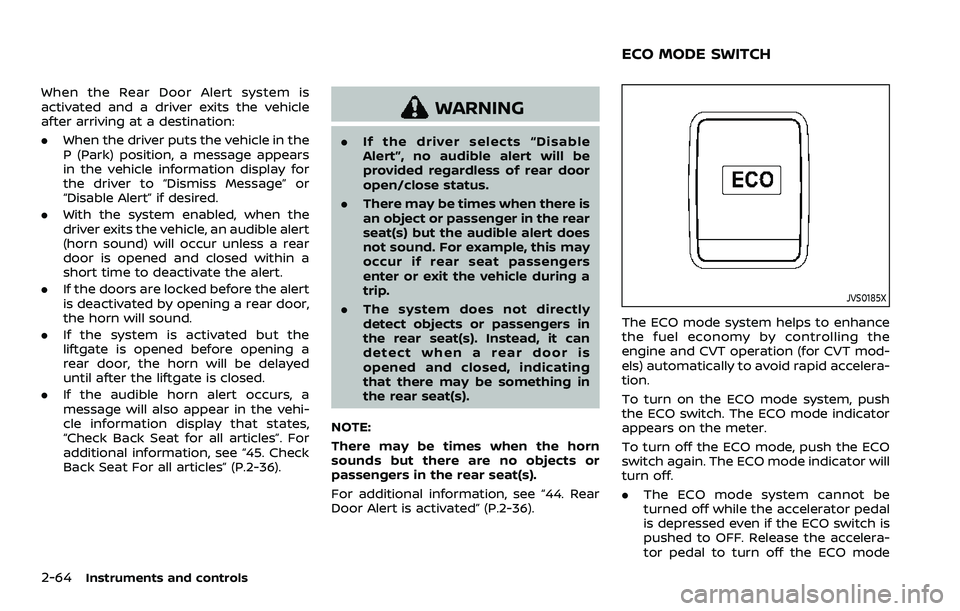
The ECO mode system helps to enhance
the fuel economy by controlling the
engine and CVT operation (for CVT mod-
els) automatically to avoid rapid accelera-
tion.
To turn on the ECO mode system, push
the ECO switch. The ECO mode indicator
appears on the meter.
To turn off the ECO mode, push the ECO
switch again. The ECO mode indicator will
turn off.
. The ECO mode system cannot be
turned off while the accelerator pedal
is depressed even if the ECO switch is
pushed to OFF. Release the accelera-
tor pedal to turn off the ECO mode
ECO MODE SWITCH
Page 147 of 508
system.
. The ECO mode system will turn off
automatically if a malfunction occurs
in the system.
. Turn off the ECO mode system when
acceleration is required such as when:
— driving with a heavy load of pas-
sengers or cargo in the vehicle
— driving on a steep uphill slope
WAC0077X
Instrument Panel
WAC0233XCenter Console Box
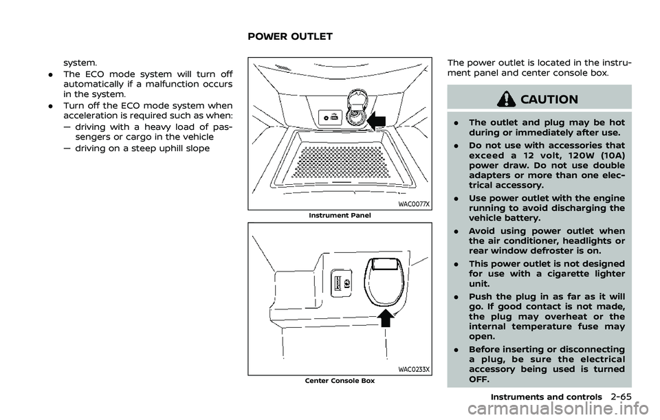
The power outlet is located in the instru-
ment panel and center console box.
CAUTION
. The outlet and plug may be hot
during or immediately after use.
. Do not use with accessories that
exceed a 12 volt, 120W (10A)
power draw. Do not use double
adapters or more than one elec-
trical accessory.
. Use power outlet with the engine
running to avoid discharging the
vehicle battery.
. Avoid using power outlet when
the air conditioner, headlights or
rear window defroster is on.
. This power outlet is not designed
for use with a cigarette lighter
unit.
. Push the plug in as far as it will
go. If good contact is not made,
the plug may overheat or the
internal temperature fuse may
open.
. Before inserting or disconnecting
a plug, be sure the electrical
accessory being used is turned
OFF.
Instruments and controls2-65
POWER OUTLET
Page 150 of 508
2-68Instruments and controls
from the TCU antenna may ad-
versely affect the operation of the
pacemaker while using the Nis-
sanConnect® Services.
WAC0510X
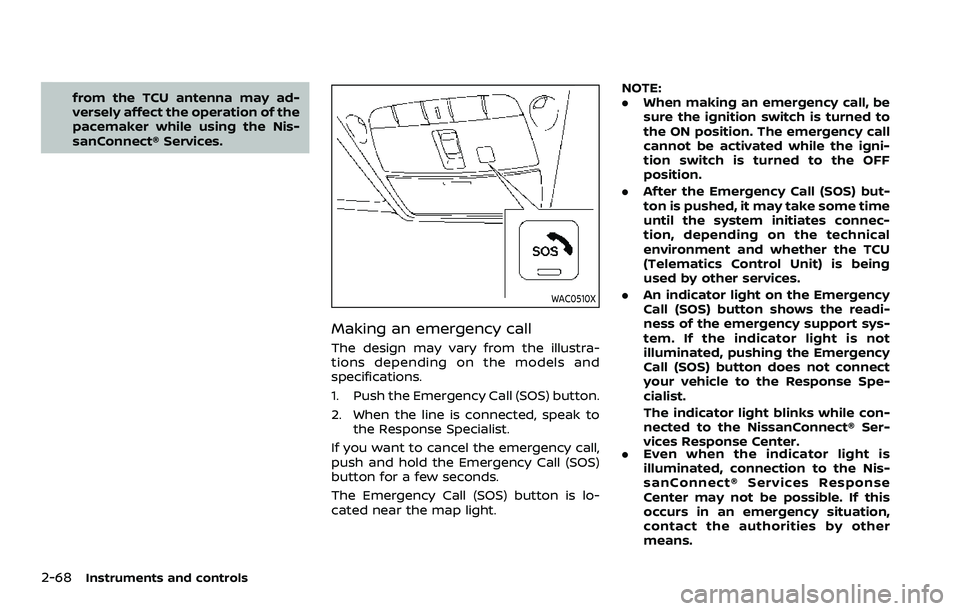
Making an emergency call
The design may vary from the illustra-
tions depending on the models and
specifications.
1. Push the Emergency Call (SOS) button.
2. When the line is connected, speak tothe Response Specialist.
If you want to cancel the emergency call,
push and hold the Emergency Call (SOS)
button for a few seconds.
The Emergency Call (SOS) button is lo-
cated near the map light. NOTE:
.
When making an emergency call, be
sure the ignition switch is turned to
the ON position. The emergency call
cannot be activated while the igni-
tion switch is turned to the OFF
position.
. After the Emergency Call (SOS) but-
ton is pushed, it may take some time
until the system initiates connec-
tion, depending on the technical
environment and whether the TCU
(Telematics Control Unit) is being
used by other services.
. An indicator light on the Emergency
Call (SOS) button shows the readi-
ness of the emergency support sys-
tem. If the indicator light is not
illuminated, pushing the Emergency
Call (SOS) button does not connect
your vehicle to the Response Spe-
cialist.
The indicator light blinks while con-
nected to the NissanConnect® Ser-
vices Response Center.
. Even when the indicator light is
illuminated, connection to the Nis-
sanConnect® Services Response
Center may not be possible. If this
occurs in an emergency situation,
contact the authorities by other
means.
Page 164 of 508
2-82Instruments and controls
SIC2063A
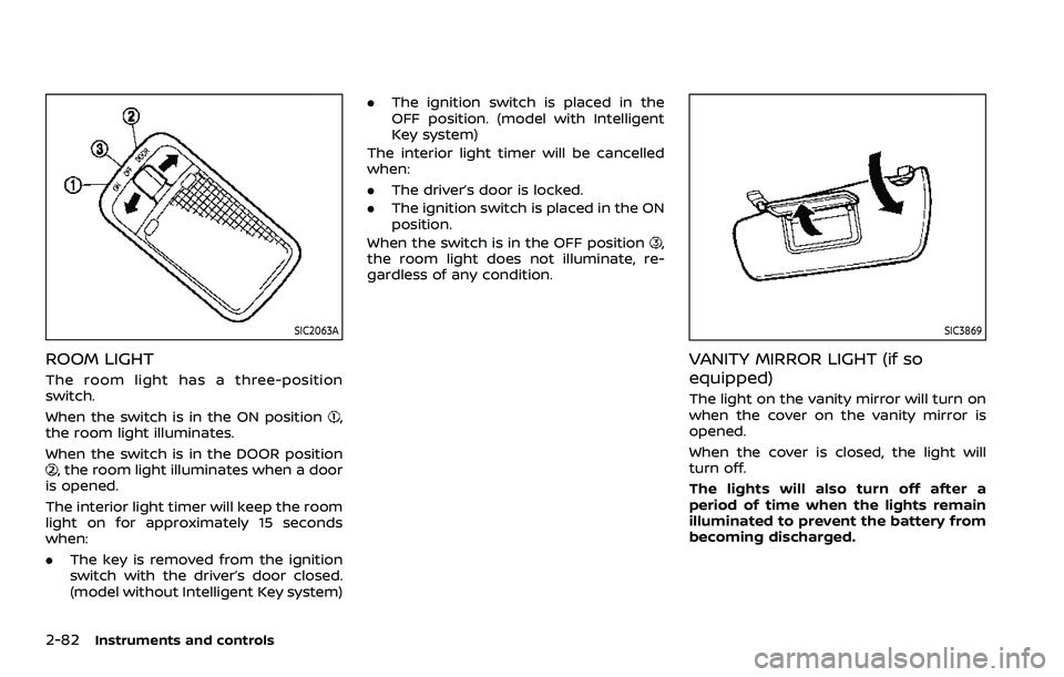
ROOM LIGHT
The room light has a three-position
switch.
When the switch is in the ON position
,
the room light illuminates.
When the switch is in the DOOR position
, the room light illuminates when a door
is opened.
The interior light timer will keep the room
light on for approximately 15 seconds
when:
. The key is removed from the ignition
switch with the driver’s door closed.
(model without Intelligent Key system) .
The ignition switch is placed in the
OFF position. (model with Intelligent
Key system)
The interior light timer will be cancelled
when:
. The driver’s door is locked.
. The ignition switch is placed in the ON
position.
When the switch is in the OFF position
,
the room light does not illuminate, re-
gardless of any condition.
SIC3869
VANITY MIRROR LIGHT (if so
equipped)
The light on the vanity mirror will turn on
when the cover on the vanity mirror is
opened.
When the cover is closed, the light will
turn off.
The lights will also turn off after a
period of time when the lights remain
illuminated to prevent the battery from
becoming discharged.
Page 165 of 508

CARGO LIGHT
The cargo lights illuminate when the
liftgate is opened. When the liftgate is
closed, the lights will turn off.
The light will also turn off after a period
of time when the light remains illumi-
nated after the ignition switch has been
pushed to the OFF position to prevent
the battery from becoming discharged.
The HomeLink® Universal Transceiver
provides a convenient way to consolidate
the functions of up to three individual
hand-held transmitters into one built-in
device.
HomeLink® Universal Transceiver:
.Will operate most Radio Frequency
(RF) devices such as garage doors,
gates, home and office lighting, entry
door locks and security systems.
. Is powered by your vehicle’s battery.
No separate batteries are required. If
the vehicle’s battery is discharged or is
disconnected, HomeLink® will retain
all programming.
When the HomeLink® Universal Trans-
ceiver is programmed, retain the origi-
nal transmitter for future programming
procedures (Example: new vehicle pur-
chases). Upon sale of the vehicle, the
programmed HomeLink® Universal
Transceiver buttons should be erased
for security purposes. For additional
information, refer to “Programming
HomeLink®” (P.2-84).
WARNING
. Do not use the HomeLink® Uni-
versal Transceiver with any gar-
age door opener that lacks safety stop and reverse features as re-
quired by federal safety stan-
dards. (These standards became
effective for opener models man-
ufactured after April 1, 1982.) A
garage door opener which cannot
detect an object in the path of a
closing garage door and then
automatically stop and reverse,
does not meet current federal
safety standards. Using a garage
door opener without these fea-
tures increases the risk of serious
injury or death.
. During the programming proce-
dure your garage door or security
gate will open and close (if the
transmitter is within range). Make
sure that people or objects are
clear of the garage door, gate,
etc. that you are programming.
. Your vehicle’s engine should be
turned off while programming
the HomeLink® Universal Trans-
ceiver. Do not breathe exhaust
gases; they contain colorless
and odorless carbon monoxide.
Carbon monoxide is dangerous. It
can cause unconsciousness or
death.
Instruments and controls2-83
HomeLink® UNIVERSAL
TRANSCEIVER (if so equipped)