Page 195 of 665
INSTRUMENT BRIGHTNESS
CONTROL
Press the “+” button to increase the bright-
ness of instrument panel lights.
Press the “-” button to decrease the bright-
ness of instrument panel lights.
TURN SIGNAL SWITCH
Turn signal
�1Move the lever up or down to signal the
turning direction. When the turn is com-
pleted, the turn signal cancels
automatically.
Lane change signal
�2Move the lever up or down until the turn
signal begins to flash, but the lever
does not latch, to signal a lane change.
Hold the lever until the lane change is
completed. Move the lever up or down until the turn
signal begins to flash, but the lever does
not latch, and release the lever. The turn
signal will automatically flash three times.
Choose the appropriate method to signal
a lane change based on road and traffic
conditions.
LIC4691LIC4692
2-88Instruments and controls
Page 196 of 665
FOG LIGHT SWITCH (if so
equipped)
To turn the fog lights on, rotate the head-
light switch to theposition, then ro-
tate the fog light switch to the
position.
To turn the fog lights on with the headlight
switch in the AUTO position, the headlights
must be on, then rotate the fog light switch
to the
position.
To turn the fog lights off, rotate the fog light
switch to the OFF position. The headlights must be on and the low
beams selected for the fog lights to oper-
ate. The fog lights automatically turn off
when the high beam headlights are
selected.
To sound the horn, push the center pad
area of the steering wheel.
WARNING
Do not disassemble the horn. Doing so
could affect proper operation of the
supplemental front air bag system.
Tampering with the supplemental
front air bag system may result in seri-
ous personal injury.
LIC4693LIC4694
HORN
Instruments and controls2-89
Page 201 of 665

WARNING
• Never rely solely on the hill descent
control system to control vehicle
speed when driving on steep down-
hill grades. Always drive carefully
when using the hill descent control
system and decelerate the vehicle
speed by depressing the brake pedal
if necessary. Be especially careful
when driving on frozen, muddy or ex-
tremely steep downhill roads. Failure
to control vehicle speed may result in
a loss of control of the vehicle and
possible serious injury or death. •
The hill descent control may not con-
trol the vehicle speed on a hill under
all load or road conditions. Always be
prepared to depress the brake pedal
to control vehicle speed. Failure to do
so may result in a collision or serious
personal injury.
CAUTION
When the hill descent control system
operates continuously for a long time,
the temperature of the brake pads may
increase and the hill descent control
system may be temporarily disabled
(the indicator light will blink). If the indi-
cator light does not come on continu-
ously af ter blinking, stop using the
system.
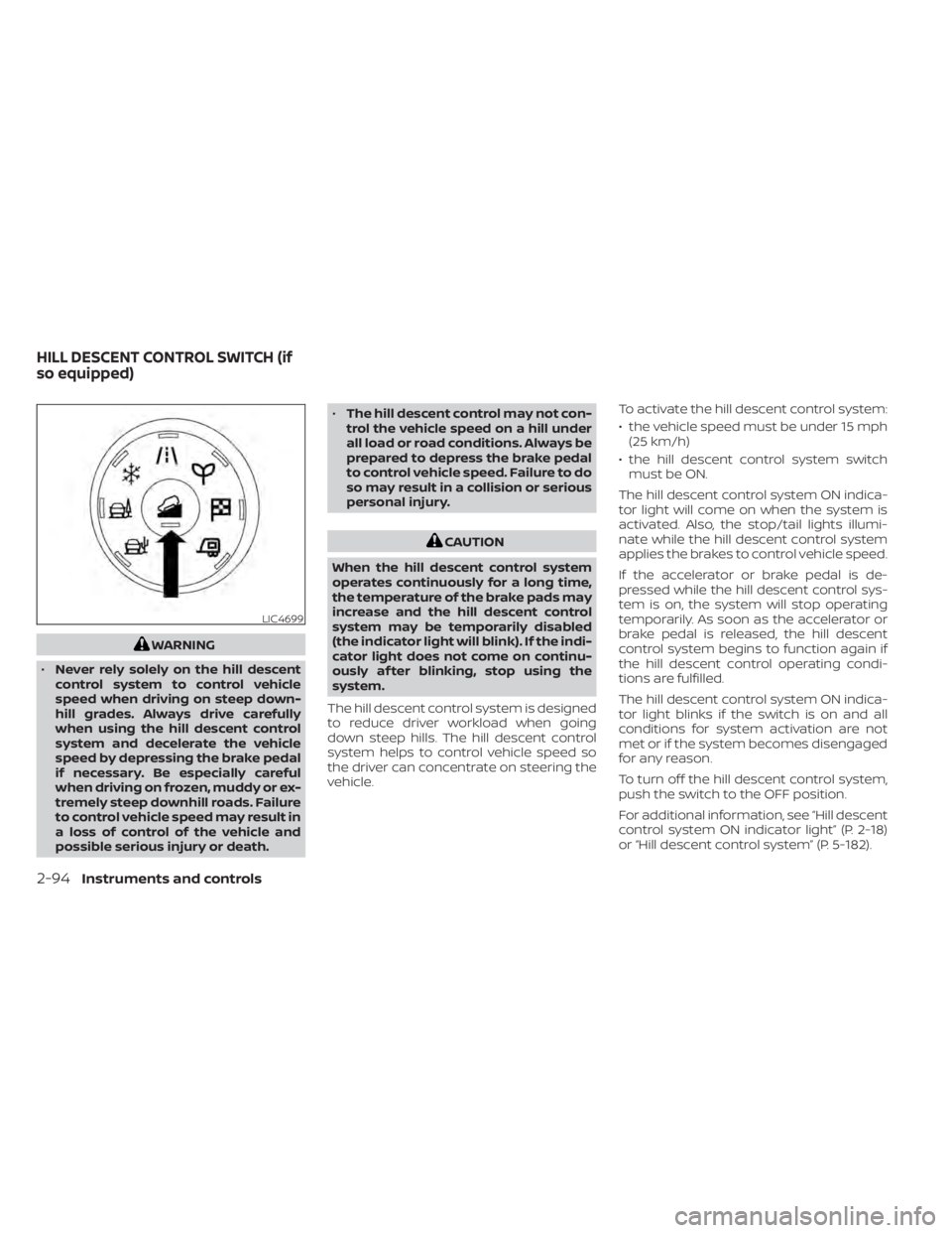
The hill descent control system is designed
to reduce driver workload when going
down steep hills. The hill descent control
system helps to control vehicle speed so
the driver can concentrate on steering the
vehicle. To activate the hill descent control system:
• the vehicle speed must be under 15 mph
(25 km/h)
• the hill descent control system switch must be ON.
The hill descent control system ON indica-
tor light will come on when the system is
activated. Also, the stop/tail lights illumi-
nate while the hill descent control system
applies the brakes to control vehicle speed.
If the accelerator or brake pedal is de-
pressed while the hill descent control sys-
tem is on, the system will stop operating
temporarily. As soon as the accelerator or
brake pedal is released, the hill descent
control system begins to function again if
the hill descent control operating condi-
tions are fulfilled.
The hill descent control system ON indica-
tor light blinks if the switch is on and all
conditions for system activation are not
met or if the system becomes disengaged
for any reason.
To turn off the hill descent control system,
push the switch to the OFF position.
For additional information, see “Hill descent
control system ON indicator light” (P. 2-18)
or “Hill descent control system” (P. 5-182).
LIC4699
HILL DESCENT CONTROL SWITCH (if
so equipped)
2-94Instruments and controls
Page 209 of 665

CAUTION
• The outlet and plug may be hot dur-
ing or immediately af ter use.
• Only certain power outlets are de-
signed for use with a cigarette lighter
unit. Do not use any other power out-
let for an accessory lighter. It is rec-
ommended that you visit a NISSAN
dealer for additional information.
• Do not use with accessories that ex-
ceed a 12 volt, 120W (10A) power draw. •
Do not use double adapters or more
than one electrical accessory.
• Use power outlets with the engine
running to avoid discharging the ve-
hicle battery.
• Avoid using power outlets when the
air conditioner, headlights, or rear
window defroster is on.
• Before inserting or disconnecting a
plug, be sure the electrical accessory
being used is turned off.
• Push the plug in as far as it will go. If
good contact is not made, the plug
may overheat or the internal tem-
perature fuse may open.
• When not in use, be sure to close the
cap. Do not allow water or any other
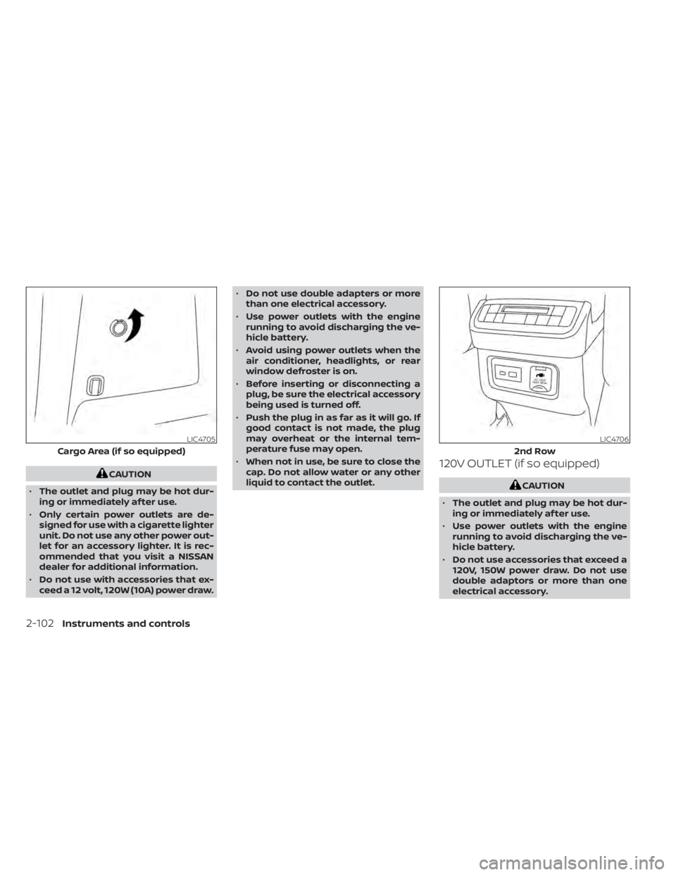
liquid to contact the outlet.120V OUTLET (if so equipped)
CAUTION
• The outlet and plug may be hot dur-
ing or immediately af ter use.
• Use power outlets with the engine
running to avoid discharging the ve-
hicle battery.
• Do not use accessories that exceed a
120V, 150W power draw. Do not use
double adaptors or more than one
electrical accessory.
LIC4705
Cargo Area (if so equipped)
LIC4706
2nd Row
2-102Instruments and controls
Page 210 of 665
•Avoid using power outlets when the
air conditioner, headlights or rear
window defroster is on.
• Before inserting or disconnecting a
plug, be sure the electrical accessory
being used is turned OFF.
• Push the plug in as far as it will go. If
good contact is not made, the plug
may overheat or the internal tem-
perature fuse may open.
• When not in use, be sure to close the
cap. Do not allow water or any other
liquid to contact the outlet.
LIC5029
1st row
LIC5031
2nd row
USB/iPod® CHARGING PORTS
Instruments and controls2-103
Page 230 of 665

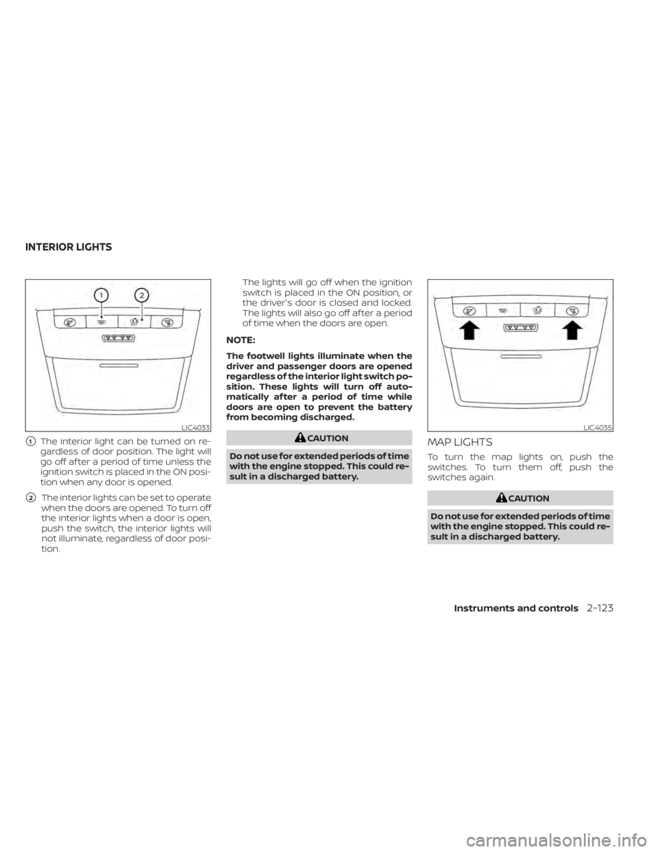
�1The interior light can be turned on re-
gardless of door position. The light will
go off af ter a period of time unless the
ignition switch is placed in the ON posi-
tion when any door is opened.
�2The interior lights can be set to operate
when the doors are opened. To turn off
the interior lights when a door is open,
push the switch, the interior lights will
not illuminate, regardless of door posi-
tion. The lights will go off when the ignition
switch is placed in the ON position, or
the driver's door is closed and locked.
The lights will also go off af ter a period
of time when the doors are open.
NOTE:
The footwell lights illuminate when the
driver and passenger doors are opened
regardless of the interior light switch po-
sition. These lights will turn off auto-
matically af ter a period of time while
doors are open to prevent the battery
from becoming discharged.
CAUTION
Do not use for extended periods of time
with the engine stopped. This could re-
sult in a discharged battery.MAP LIGHTS
To turn the map lights on, push the
switches. To turn them off, push the
switches again.
CAUTION
Do not use for extended periods of time
with the engine stopped. This could re-
sult in a discharged battery.
LIC4033LIC4035
INTERIOR LIGHTS
Instruments and controls2-123
Page 231 of 665
PERSONAL LIGHTS
To turn on the personal lights, push and
release the switch
O1.
To turn off the personal lights, push and
release the switch
O1.
CARGO LIGHT
The cargo light on the overhead trim has a
three-position switch. To operate, push the
switch to the desired position.
�1ON: The light is illuminated.
�2DOOR: The light illuminates when the
lif tgate is opened. The light turns off
when the lif tgate is closed.
�3OFF: The light does not illuminate re-
gardless of lif tgate position or lock
status.
CAUTION
Do not use for extended periods of time
with the engine stopped. This could re-
sult in a discharged battery.
LIC1413SIC2063A
2-124Instruments and controls
Page 247 of 665

Locking doors
1. Push the P (Park) button, place the igni-tion switch in the LOCK position and
make sure you carry the Intelligent Key
with you.
2. Close all doors.
3. Push any door handle lock sensor while carrying the Intelligent Key with you.
4. All doors will lock.
5. The hazard indicator lights flash twice and the outside buzzer sounds twice.
NOTE:
• Lock sensors for all doors can be deac-tivated when the Ext. Door Switch fea-
ture is switched to OFF using the “Ve-
hicle Settings” menu in the vehicle
information display. For additional in-
formation, see “Vehicle information
display 7 inch (18 cm) Type A” (P. 2-23)
or “Vehicle information display 12.3
inch (31 cm) Type B” (P. 2-48). • Doors do not lock with the door handle
lock sensor with the Intelligent Key in-
side the vehicle and a beep sounds to
warn you. However, when an Intelligent
Key is inside the vehicle, doors can be
locked with another Intelligent Key.
• Touching the door lock sensor while wearing gloves may delay or prevent
lock operation. Remove the gloves and
touch the lock sensor again.
• If the door handle becomes wet while the electronic key is within the effec-
tive range, the door may lock and un-
lock repeatedly. In this case, follow the
following correction procedures to
wash the vehicle:– Place the electronic key in a location 6 f t. (2 m) or more away from the
vehicle. (Take care to ensure that the
key is not stolen.)
– If the electronic key is inside the ve- hicle and a door handle becomes
wet during a car wash, a buzzer will
sound outside the vehicle. To turn off
the alarm, away the key from the in-
side vehicle.
• The lock sensor may not work properly if it comes in contact with ice, snow,
mud, etc. Clean the lock sensor and at-
tempt to operate it again.
LPD3373LPD3269
3-10Pre-driving checks and adjustments