2023 NISSAN ALTIMA wheel torque
[x] Cancel search: wheel torquePage 416 of 644

If the steering wheel is not operated or the
driver takes his/her hands off the steering
wheel for a period of time, the warning
O1
appears in the vehicle information display.
If the driver does not operate the steering
wheel af ter the warning has been dis-
played, an audible alert sounds and the
warning flashes in the vehicle information
display, followed by a quick brake applica-
tion to request the driver to take control of
the vehicle again.
If the driver still does not respond, the Pro-
PILOT Assist turns on the hazard flasher
and slows the vehicle to a complete stop.
The driver can cancel the deceleration at
any time by steering, braking, accelerating,
or operating the ProPILOT Assist switch.
WARNING
Steering Assist is not a system for
hands-free driving. Always keep your
hands on the steering wheel and drive
your vehicle safely. Failure to do so
could cause a collision resulting in seri-
ous personal injury or death.
NOTE:
If the driver lightly touches (instead of
firmly grips) the steering wheel, the
steering torque sensor may not detect
the driver’s hand(s) on the wheel and a
sequence of warnings may occur. When
the driver holds and operates the steer-
ing wheel again, the warnings turn off.
Steering Assist limitations
WARNING
• In the following situations, the cam-
era may not detect lane markers cor-
rectly or may detect lane markers in-
correctly and the Steering Assist may
not operate properly:
– When driving on roads where
there are multiple parallel lane
markers, lane markers that are
faded or not painted clearly, non-
standard lane markers, or lane
markers covered with water, dirt,
snow, etc.
– When driving on roads with dis-
continued lane markers
– When driving on roads with a wid-
ening or narrowing lane width –
When driving on roads where
there are multiple lanes or unclear
lane markers due to road
construction
– When driving on roads where
there are sharply contrasting ob-
jects, such as shadows, snow, wa-
ter, wheel ruts, seams, or lines re-
maining af ter road repairs (the
Steering Assist could detect these
items as lane markers)
– When driving on roads where the
traveling lane merges or
separates
• Do not use the Steering Assist under
the following conditions because the
system may not properly detect lane
markers. Doing so could cause a loss
of vehicle control and result in an ac-
cident.
– During bad weather (rain, fog,
snow, dust, etc.)
– When rain, snow, sand, etc., is
thrown up by the wheels of other
vehicles
– When dirt, oil, ice, snow, water, or
another object adheres to the
camera unit
5-120Starting and driving
Page 474 of 644

The chassis control is an electric control
module that includes the following
functions:
• Intelligent Trace Control
• Active Ride Control
INTELLIGENT TRACE CONTROL
(I-TC)
This system senses driving based on the
driver’s steering and acceleration/braking
patterns, and controls brake pressure at
individual wheels to aid tracing at corners
and help smooth vehicle response.
The I-TC can be set to on (enabled) or off
(disabled) through the vehicle information
display “Settings” page. For additional infor-
mation, see “Vehicle information display —
5 inch (13 cm) Type A (if so equipped)”
(P. 2-18) or “Vehicle information display — 7
inch (18 cm) Type B (if so equipped)” (P. 2-34).
When the VDC system is turned off, the I-TC
is also turned off.
WARNING
The I-TC may not be effective depend-
ing on the driving condition. Always
drive carefully and attentively. When the I-TC is operating, you may feel a
pulsation in the brake pedal and hear a
noise. This is normal and indicates that the
I-TC is operating properly.
Even if the I-TC is turned off, some functions
will remain on to assist the driver (for ex-
ample, avoidance scenes).
ACTIVE RIDE CONTROL (ARC)
This system senses upper body motion
(based on wheel speed information) and
controls engine torque and four wheel
brake pressure. This will enhance ride com-
fort in effort to restrain uncomfortable up-
per body movement when passing over
undulated road surfaces. This system
comes into effect above 25 mph (40 km/h).
When the VDC system is turned off, the ARC
is also turned off.
When the ARC is operating, you may hear
noise and sense slight deceleration. This is
normal and indicates that the ARC is oper-
ating properly.
WARNING
• Never rely solely on the hill start as-
sist system to prevent the vehicle
from moving backward on a hill. Al-
ways drive carefully and attentively.
Depress the brake pedal when the
vehicle is stopped on a steep hill. Be
especially careful when stopped on a
hill on frozen or muddy roads. Failure
to prevent the vehicle from rolling
backwards may result in a loss of
control of the vehicle and possible
serious injury or death.
• The hill start assist system is not de-
signed to hold the vehicle at a stand-
still on a hill. Depress the brake pedal
when the vehicle is stopped on a
steep hill. Failure to do so may cause
the vehicle to roll backwards and
may result in a collision or serious
personal injury.
• The hill start assist system may not
prevent the vehicle from rolling
backwards on a hill under all load or
road conditions. Always be prepared
to depress the brake pedal to prevent
the vehicle from rolling backwards.
Failure to do so may result in a colli-
sion or serious personal injury.
CHASSIS CONTROL (if so equipped) HILL START ASSIST SYSTEM
5-178Starting and driving
Page 493 of 644

Always refer to the illustration for the cor-
rect placement and jack-up points for your
specific vehicle model and jack type.
Carefully read the caution label attached
to the jack body and the following
instructions.
If a flat tire occurs on the front axle of AWD
vehicle, the spare tire must be applied to
the rear axle of the vehicle.
1. Loosen each wheel nut one or two turnsby turning counterclockwise with the
wheel nut wrench. Do not remove the
wheel nuts until the tire is off the
ground. 2. Place the jack directly under the jack-up
point as illustrated so the top of the jack
contacts the vehicle at the jack-up point.
Align the jack head between the two
notches in the front or the rear as
shown. Also fit the groove of the jack
head between the notches as shown.
NOTE:Do not place jack on the notches be-
tween the front most and rear most
jacking points.
The jack should be used on firm and
level ground. 3. Jack up the rear axle of the vehicle. To lif t
the vehicle, securely hold the jack lever
and rod with both hands. Carefully raise
the vehicle until the tire clears the
ground. Remove the wheel nuts, and
then remove the tire and set aside.
4. Apply the spare tire to the rear axle of the vehicle, replace the wheel nuts and
tighten.
5. Lower the jack and further tighten the wheel nuts to the recommended
torque, see “Installing the spare tire”
(P. 6-10).
6. Jack up the front axle of the vehicle and remove the damaged wheel.
7. Apply the wheel that was removed from the rear axle to the front axle of the ve-
hicle, replace the wheel nuts and tighten.
8. Lower the jack and further tighten the wheel nuts to the recommended
torque, see “Installing the spare tire”
(P. 6-10).
LCE0020
In case of emergency6-9
Page 494 of 644

Installing the spare tire
WARNING
For AWD vehicles - the TEMPORARY USE
ONLY spare tire must be installed to the
rear wheels only. If a front tire is punc-
tured, install the original rear tire onto
the front wheel, then install the TEMPO-
RARY USE ONLY spare tire on the rear.
Failure to do so could cause overheat-
ing to the AWD system
The spare tire is designed for emergency
use. For additional information, see
“Wheels and tires” (P. 8-29). 1. Clean any mud or dirt from the surface
between the wheel and hub.
2. Carefully put the spare tire on and tighten the wheel nuts finger tight.
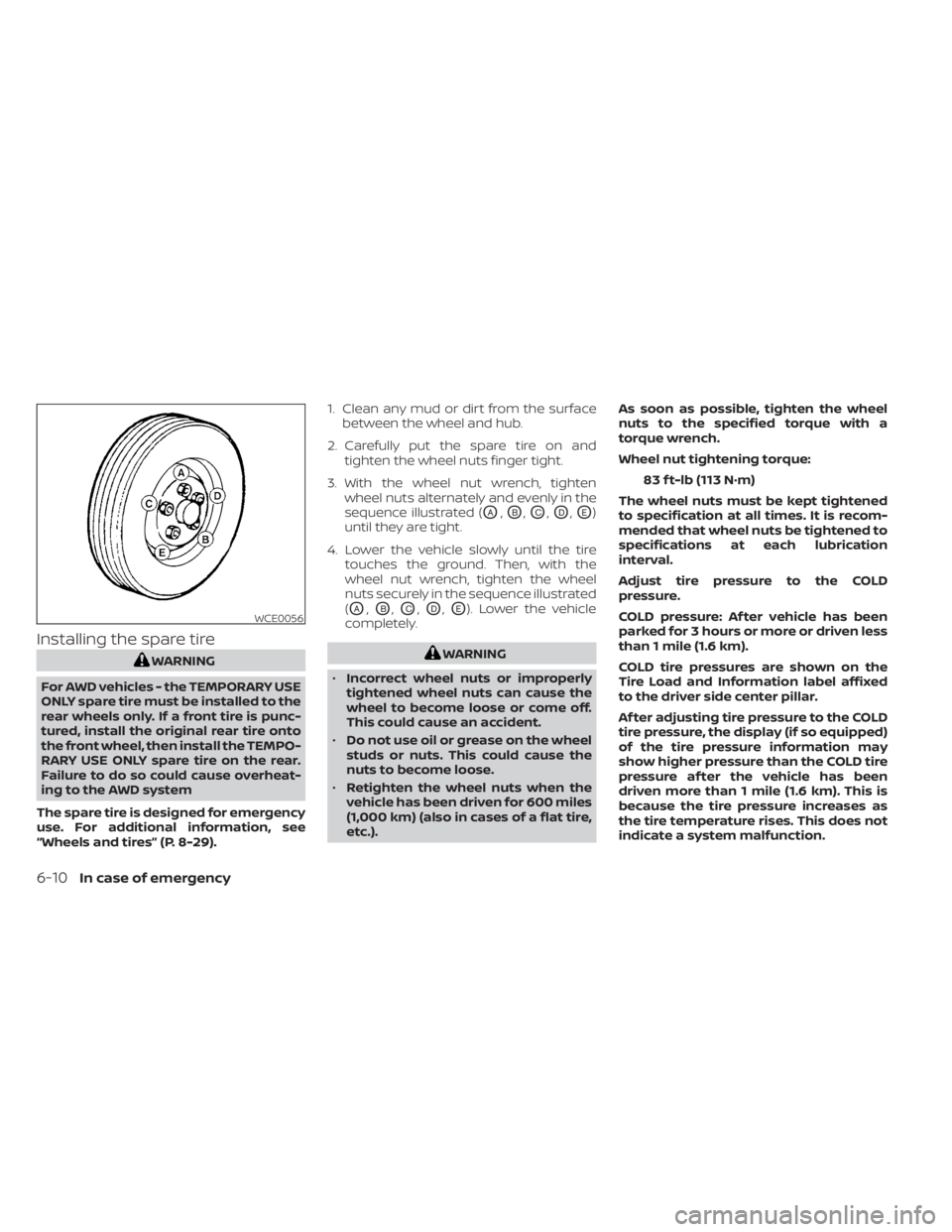
3. With the wheel nut wrench, tighten wheel nuts alternately and evenly in the
sequence illustrated (
OA,OB,OC,OD,OE)
until they are tight.
4. Lower the vehicle slowly until the tire touches the ground. Then, with the
wheel nut wrench, tighten the wheel
nuts securely in the sequence illustrated
(
OA,OB,OC,OD,OE). Lower the vehicle
completely.
WARNING
• Incorrect wheel nuts or improperly
tightened wheel nuts can cause the
wheel to become loose or come off.
This could cause an accident.
• Do not use oil or grease on the wheel
studs or nuts. This could cause the
nuts to become loose.
• Retighten the wheel nuts when the
vehicle has been driven for 600 miles
(1,000 km) (also in cases of a flat tire,
etc.). As soon as possible, tighten the wheel
nuts to the specified torque with a
torque wrench.
Wheel nut tightening torque:
83 f t-lb (113 N·m)
The wheel nuts must be kept tightened
to specification at all times. It is recom-
mended that wheel nuts be tightened to
specifications at each lubrication
interval.
Adjust tire pressure to the COLD
pressure.
COLD pressure: Af ter vehicle has been
parked for 3 hours or more or driven less
than 1 mile (1.6 km).
COLD tire pressures are shown on the
Tire Load and Information label affixed
to the driver side center pillar.
Af ter adjusting tire pressure to the COLD
tire pressure, the display (if so equipped)
of the tire pressure information may
show higher pressure than the COLD tire
pressure af ter the vehicle has been
driven more than 1 mile (1.6 km). This is
because the tire pressure increases as
the tire temperature rises. This does not
indicate a system malfunction.
WCE0056
6-10In case of emergency
Page 555 of 644

CHANGING WHEELS AND TIRES
Tire rotation
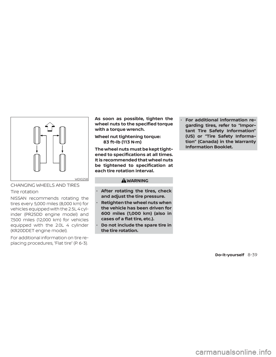
NISSAN recommends rotating the
tires every 5,000 miles (8,000 km) for
vehicles equipped with the 2.5L 4 cyl-
inder (PR25DD engine model) and
7,500 miles (12,000 km) for vehicles
equipped with the 2.0L 4 cylinder
(KR20DDET engine model).
For additional information on tire re-
placing procedures, “Flat tire” (P. 6-3).As soon as possible, tighten the
wheel nuts to the specified torque
with a torque wrench.
Wheel nut tightening torque:
83 f t-lb (113 N·m)
The wheel nuts must be kept tight-
ened to specifications at all times.
It is recommended that wheel nuts
be tightened to specification at
each tire rotation interval.
WARNING
• Af ter rotating the tires, check
and adjust the tire pressure.
• Retighten the wheel nuts when
the vehicle has been driven for
600 miles (1,000 km) (also in
cases of a flat tire, etc.).
• Do not include the spare tire in
the tire rotation. •
For additional information re-
garding tires, refer to “Impor-
tant Tire Safety Information”
(US) or “Tire Safety Informa-
tion” (Canada) in the Warranty
Information Booklet.WDI0258
Do-it-yourself8-39