2023 NISSAN ALTIMA lights
[x] Cancel search: lightsPage 437 of 644
–When your vehicle or the vehicle
or pedestrian ahead moves
quickly or significantly such that
the system cannot detect and re-
act in time (for example, pedes-
trian moving quickly toward the
vehicle at close range, vehicle cut-
ting in, changing lanes, making a
turn, steering abruptly, sudden
acceleration or deceleration).
– When the vehicle or pedestrian is
offset from the vehicle’s forward
path.
– If the speed difference between
the two vehicles is small.
– The pedestrian’s profile is par-
tially obscured or unidentifiable;
for example, due to transporting
luggage, pushing a stroller, wear-
ing bulky or very loose-fitting
clothing or accessories, or being
in a unique posture (such as rais-
ing hands).
– There is poor contrast of a person
to the background, such as having
clothing color or pattern which is
similar to the background.
– For approximately 15 seconds af-
ter starting the engine. –
If the vehicle ahead has a unique
or unusual shape, extremely low
or high clearance heights, or un-
usual cargo loading or is narrow
(for example, a motorcycle).
– When the vehicle or pedestrian is
located near a traffic sign, a reflec-
tive area (for example, water on
road), or is in a shadow.
– When multiple pedestrians are
grouped together.
– When the view of the pedestrian is
obscured by a vehicle or other
object.
– While towing a trailer or other
vehicle.
• The system performance may be de-
graded in the following conditions:
– The vehicle is driven on a slippery
road.
– The vehicle is driven on a slope.
– Excessively heavy baggage is
loaded in the rear seat or the
cargo area of your vehicle.
• The system is designed to automati-
cally check the sensor’s (radar and
camera) functionality, within certain
limitations. The system may not de-
tect some forms of obstruction of the
sensor area such as ice, snow or stickers, for example. In these cases,
the system may not be able to warn
the driver properly. Be sure that you
check, clean and clear sensor areas
regularly.
• In some road and traffic conditions,
the AEB with Pedestrian Detection
system may unexpectedly apply par-
tial braking. When acceleration is
necessary, depress the accelerator
pedal to override the system.
• The AEB with Pedestrian Detection
system may operate when a pattern,
object, shadow or lights are detected
that are similar to the outline of ve-
hicles or pedestrians, or if they are
the same size and position as a ve-
hicle or motorcycle’s tail lights.
• The system may keep operating
when the vehicle ahead is turning
right or lef t.
• The system may operate when your
vehicle is approaching and passing a
vehicle ahead.
•
Depending on the road shape (curved
road, entrance and exit of the curve,
winding road, lane regulation, under
construction, etc.), the system may
operate temporarily for the oncoming
vehicle in front of your vehicle.
Starting and driving5-141
Page 463 of 644
CAUTION
During the first 1,200 miles (2,000 km),
follow these recommendations to ob-
tain maximum engine performance
and ensure the future reliability and
economy of your new vehicle. Failure to
follow these recommendations may
result in shortened engine life and re-
duced engine performance.
• Avoid driving for long periods at constant speed, either fast or slow, and do not run
the engine over 4,000 rpm.
• Do not accelerate at full throttle in any gear.
• Avoid quick starts.
• Avoid hard braking as much as possible. Follow these easy-to-use Fuel Efficient
Driving Tips to help you achieve the most
fuel economy from your vehicle.
1.
Use Smooth Accelerator and Brake
Pedal Application
• Avoid rapid starts and stops.
• Use smooth, gentle accelerator and brake application whenever possible.
• Maintain constant speed while com- muting and coast whenever possible.
2. Maintain Constant Speed
• Look ahead to try and anticipate and minimize stops.
• Synchronizing your speed with traffic lights allows you to reduce your num-
ber of stops.
• Maintaining a steady speed can mini- mize red light stops and improve fuel
efficiency.
3. Use Air Conditioning (A/C) at Higher
Vehicle Speeds
• Below 40 mph (64 km/h), it is more efficient to open windows to cool the
vehicle due to reduced engine load.
• Above 40 mph (64 km/h), it is more efficient to use A/C to cool the vehicle
due to increased aerodynamic drag. • Recirculating the cool air in the cabin
when the A/C is on reduces cooling
load.
4. Drive at Economical Speeds and
Distances
• Observing the speed limit and not ex- ceeding 60 mph (97 km/h) (where le-
gally allowed) can improve fuel effi-
ciency due to reduced aerodynamic
drag.
• Maintaining a safe following distance behind other vehicles reduces unnec-
essary braking.
• Safely monitoring traffic to anticipate changes in speed permits reduced
braking and smooth acceleration
changes.
• Select a gear range suitable to road conditions.
5. Use Cruise Control
• Using cruise control during highway driving helps maintain a steady speed.
• Cruise control is particularly effective in providing fuel savings when driving
on flat terrains.
6. Plan for the Shortest Route
• Utilize a map or navigation system to determine the best route to save time.
BREAK-IN SCHEDULE FUEL EFFICIENT DRIVING TIPS
Starting and driving5-167
Page 472 of 644
When the VDC system is turned off in the
vehicle information display, the VDC sys-
tem still operates to prevent one drive
wheel from slipping by transferring power
to a non-slipping drive wheel. The
indicator light flashes if this occurs. All
other VDC functions are off and the
indicator light will not flash.
The VDC system is automatically reset to
ON when the ignition switch is placed in the
OFF position then back to the ON position.
The computer has a built-in diagnostic fea-
ture that tests the system each time you
start the engine and move the vehicle for-
ward or in reverse at a slow speed. When
the self-test occurs, you may hear a clunk
noise and/or feel a pulsation in the brake
pedal. This is normal and is not an indica-
tion of a malfunction.
WARNING
• The VDC system is designed to help
the driver maintain stability but does
not prevent accidents due to abrupt
steering operation at high speeds or
by careless or dangerous driving
techniques. Reduce vehicle speed
and be especially careful when driv-
ing and cornering on slippery sur-
faces and always drive carefully.
• Do not modif y the vehicle's suspen-
sion. If suspension parts such as
shock absorbers, struts, springs, sta-
bilizer bars, bushings and wheels are
not NISSAN recommended for your
vehicle or are extremely deterio-
rated, the VDC system may not oper-
ate properly. This could adversely af-
fect vehicle handling performance,
and the
indicator light may flash
or theindicator light may
illuminate.
• If brake related parts such as brake
pads, rotors and calipers are not
NISSAN recommended or are ex-
tremely deteriorated, the VDC sys-
tem may not operate properly and
both the
andindicator
lights may illuminate. •
If engine control related parts are not
NISSAN recommended or are ex-
tremely deteriorated, both the
and theindicator lights may
illuminate.
• When driving on extremely inclined
surfaces such as higher banked cor-
ners, the VDC system may not oper-
ate properly and the
indicator
light may flash or theindicator
light may illuminate. Do not drive on
these types of roads.
• When driving on an unstable surface
such as a turntable, ferry, elevator or
ramp, the
indicator light may
flash or theindicator light may
illuminate. This is not a malfunction.
Restart the engine af ter driving onto
a stable surface.
• If wheels or tires other than the
NISSAN recommended ones are
used, the VDC system may not oper-
ate properly and the
indicator
light may flash or theindicator
light may illuminate.
• The VDC system is not a substitute
for winter tires or tire chains on a
snow covered road.
5-176Starting and driving
Page 486 of 644
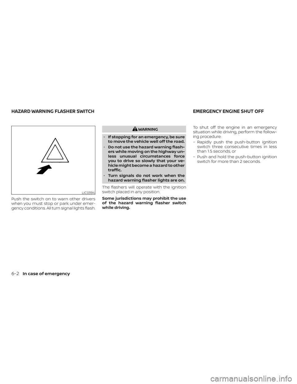
Push the switch on to warn other drivers
when you must stop or park under emer-
gency conditions. All turn signal lights flash.
WARNING
• If stopping for an emergency, be sure
to move the vehicle well off the road.
• Do not use the hazard warning flash-
ers while moving on the highway un-
less unusual circumstances force
you to drive so slowly that your ve-
hicle might become a hazard to other
traffic.
• Turn signals do not work when the
hazard warning flasher lights are on.
The flashers will operate with the ignition
switch placed in any position.
Some jurisdictions may prohibit the use
of the hazard warning flasher switch
while driving. To shut off the engine in an emergency
situation while driving, perform the follow-
ing procedure:
– Rapidly push the push-button ignition
switch three consecutive times in less
than 1.5 seconds, or
– Push and hold the push-button ignition switch for more than 2 seconds.
LIC0394
HAZARD WARNING FLASHER SWITCH EMERGENCY ENGINE SHUT OFF
6-2In case of emergency
Page 487 of 644
TIRE PRESSURE MONITORING
SYSTEM (TPMS)
This vehicle is equipped with the Tire Pres-
sure Monitoring system (TPMS). It monitors
tire pressure of all tires except the spare.
When the low tire pressure warning light is
lit, and the “Tire Pressure Low - Add Air”
warning appears in the vehicle information
display, one or more of your tires is signifi-
cantly under-inflated. If equipped, the sys-
tem also displays pressure of all tires (ex-
cept the spare tire) on the display screen by
sending a signal from a sensor that is in-
stalled in each wheel. If the vehicle is being
driven with low tire pressure, the TPMS will
activate and warn you of it by the low tire
pressure warning light. This system will ac-
tivate only when the vehicle is driven at
speeds above 16 mph (25 km/h). For addi-
tional information, see “Warning lights, indi-
cator lights and audible reminders” (P. 2-9)
and “Tire Pressure Monitoring System
(TPMS)” (P. 5-5).
WARNING
• Radio waves could adversely affect
electric medical equipment. Those
who use a pacemaker should contact
the electric medical equipment
manufacturer for the possible influ-
ences before use.
• If the low tire pressure warning light
illuminates while driving, avoid sud-
den steering maneuvers or abrupt
braking, reduce vehicle speed, pull
off the road to a safe location and
stop the vehicle as soon as possible.
Driving with under-inflated tires may
permanently damage the tires and
increase the likelihood of tire failure.
Serious vehicle damage could occur
and may lead to an accident and
could result in serious personal in-
jury. Check the tire pressure for all
four tires. Adjust the tire pressure to
the recommended COLD tire pres-
sure shown on the Tire and Loading
Information label to turn the low tire
pressure warning light OFF. If the
light still illuminates while driving af-
ter adjusting the tire pressure, a tire
may be flat or the TPMS may be mal-
functioning. If you have a flat tire, re-
place it with a spare tire as soon as possible. If no tire is flat and all tires
are properly inflated, have the ve-
hicle checked. It is recommended
that you visit a NISSAN dealer for this
service.
• When using a wheel without the
TPMS such as the spare tire, the TPMS
will not function and the low tire
pressure warning light will flash for
approximately one minute. Have
your tires replaced and/or TPMS sys-
tem reset as soon as possible. It is
recommended that you visit a
NISSAN dealer for these services.
• Replacing tires with those not origi-
nally specified by NISSAN could af-
fect the proper operation of the
TPMS.
• The Genuine NISSAN Emergency Tire
Repair Sealant or equivalent can be
used for temporarily repairing a tire.
Do not inject any other tire liquid or
aerosol tire sealant into the tires, as
this may cause a malfunction of tire
pressure sensors.
FLAT TIRE
In case of emergency6-3
Page 502 of 644
WARNING
Always follow the instructions below.
Failure to do so could result in damage
to the charging system and cause per-
sonal injury.
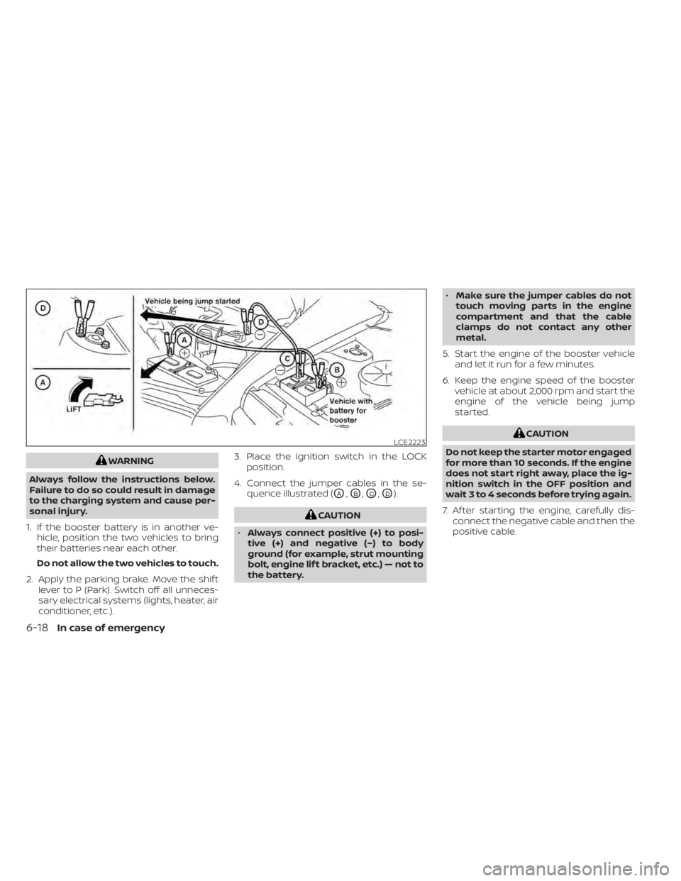
1. If the booster battery is in another ve- hicle, position the two vehicles to bring
their batteries near each other.
Do not allow the two vehicles to touch.
2. Apply the parking brake. Move the shif t lever to P (Park). Switch off all unneces-
sary electrical systems (lights, heater, air
conditioner, etc.). 3. Place the ignition switch in the LOCK
position.
4. Connect the jumper cables in the se- quence illustrated (
OA,OB,OC,OD).
CAUTION
• Always connect positive (+) to posi-
tive (+) and negative (−) to body
ground (for example, strut mounting
bolt, engine lif t bracket, etc.) — not to
the battery. •
Make sure the jumper cables do not
touch moving parts in the engine
compartment and that the cable
clamps do not contact any other
metal.
5. Start the engine of the booster vehicle and let it run for a few minutes.
6. Keep the engine speed of the booster vehicle at about 2,000 rpm and start the
engine of the vehicle being jump
started.
CAUTION
Do not keep the starter motor engaged
for more than 10 seconds. If the engine
does not start right away, place the ig-
nition switch in the OFF position and
wait 3 to 4 seconds before trying again.
7. Af ter starting the engine, carefully dis- connect the negative cable and then the
positive cable.LCE2223
6-18In case of emergency
Page 517 of 644

8 Do-it-yourself
Maintenance precautions.......................8-2
Engine compartment check locations ...........8-3
Engine cooling system ..........................8-5
Checking engine coolant level ................8-6
Changing engine coolant ....................8-6
Engine oil .......................................8-7
Checking engine oil level .....................8-7
Changing engine oil and oil filter ..............8-8
Continuously Variable Transmission (CVT)
fluid ............................................ 8-12
Brake fluid ...................................... 8-12
Windshield-washer fluid ........................8-13
Windshield-washer fluid reservoir ...........8-13
Battery......................................... 8-14
Jump starting ............................... 8-15
Variable voltage control system ................8-16
Drive belt ....................................... 8-16
Spark plugs .................................... 8-17
Replacing spark plugs ....................... 8-17
Air cleaner ..................................... 8-18In-cabin microfilter
.......................... 8-18
Windshield wiper blades ........................8-19
Cleaning .................................... 8-19
Replacing ................................... 8-19
Brakes ......................................... 8-20
Fuses .......................................... 8-21
Engine compartment ....................... 8-21
Passenger compartment ...................8-22
Battery replacement ........................... 8-23
NISSAN Intelligent Key® ......................8-24
Lights .......................................... 8-25
Headlights .................................. 8-25
Fog lights (if so equipped) ...................8-26
Exterior and interior lights ...................8-26
Wheels and tires ............................... 8-29
Tire pressure ................................ 8-29
Tire labeling ................................. 8-33
Types of tires ................................
8-36
Tir
e chains .................................. 8-37
Changing wheels and tires ..................8-39
Page 541 of 644
It is recommended that you visit a NISSAN
dealer for this service if you need assis-
tance for replacement.
FCC Notice:
For USA:
This device complies with Part 15 of the
FCC Rules. Operation is subject to the fol-
lowing two conditions: (1) This device
may not cause harmful interference, and
(2) this device must accept any interfer-
ence received, including interference
that may cause undesired operation.
NOTE:
Changes or modifications not expressly
approved by the party responsible for
compliance could void the user’s author-
ity to operate the equipment.
For Canada:
This device contains licence-exempt
transmitter(s)/receiver(s) that comply
with Innovation, Science and Economic
Development Canada’s licence-exempt
RSS(s). Operation is subject to the fol-
lowing two conditions: (1) This device
may not cause interference. (2) This de-
vice must accept any interference, in-
cluding interference that may cause un-
desired operation of the device.HEADLIGHTS
For additional information on headlight
bulb replacement, refer to the instructions
outlined in this section.
Replacing the halogen headlight
bulb (if so equipped)
The headlight is a semi-sealed beam type
which uses a replaceable headlight (halo-
gen) bulb. They can be replaced from inside
the engine compartment without remov-
ing the headlight assembly.
If headlight bulb replacement is required, it
is recommended that you visit a NISSAN
dealer for this service.
CAUTION
• Aiming is not necessary af ter replac-
ing the bulb. When aiming adjust-
ment is necessary, it is recom-
mended that you visit a NISSAN
dealer for this service. •
Do not leave the headlight assembly
open without a bulb installed for a
long period of time. Dust, moisture,
smoke, etc. entering the headlight
body may affect bulb performance.
Remove the bulb from the headlight
assembly just before a replacement
bulb is installed.
• Only touch the base when handling
the bulb. Never touch the glass enve-
lope. Touching the glass could sig-
nificantly affect bulb life and/or
headlight performance.
• High pressure halogen gas is sealed
inside the halogen bulb. The bulb
may break if the glass envelope is
scratched or the bulb is dropped.
• Use the same number and wattage
as shown in the chart.
Fog may temporarily form inside the lens
of the exterior lights in the rain or in a car
wash. A temperature difference between
the inside and the outside of the lens
causes the fog. This is not a malfunction. If
large drops of water collect inside the lens,
it is recommended that you visit a NISSAN
dealer for this service.
LIGHTS
Do-it-yourself8-25