2023 NISSAN ALTIMA brake light
[x] Cancel search: brake lightPage 470 of 644
•Tire type and condition may also af-
fect braking effectiveness.
– When replacing tires, install the
specified size of tires on all four
wheels.
– When installing a spare tire, make
sure that it is the proper size and
type as specified on the Tire and
Loading Information label. For ad-
ditional information, see “Tire and
Loading Information label”
(P. 10-14).
– For additional information, see
“Wheels and tires” (P. 8-29).
The ABS controls the brakes so the wheels
do not lock during hard braking or when
braking on slippery surfaces. The system
detects the rotation speed at each wheel
and varies the brake fluid pressure to pre-
vent each wheel from locking and sliding.
By preventing each wheel from locking, the
system helps the driver maintain steering
control and helps to minimize swerving
and spinning on slippery surfaces.Using the system
Depress the brake pedal and hold it down.
Depress the brake pedal with firm steady
pressure, but do not pump the brakes. The
Anti-lock Braking System will operate to
prevent the wheels from locking up. Steer
the vehicle to avoid obstacles.
WARNING
Do not pump the brake pedal. Doing so
may result in increased stopping
distances.
Self-test feature
The Anti-lock Braking System (ABS) in-
cludes electronic sensors, electric pumps,
hydraulic solenoids and a computer. The
computer has a built-in diagnostic feature
that tests the system each time you start
the engine and move the vehicle at a low
speed in forward or reverse. When the self-
test occurs, you may hear a “clunk” noise
and/or feel a pulsation in the brake pedal.
This is normal and does not indicate a mal-
function. If the computer senses a mal-
function, it switches the ABS off and illumi-
nates the ABS warning light on the instrument panel. The brake system then
operates normally but without anti-lock
assistance.
If the ABS warning light illuminates during
the self-test or while driving, have the ve-
hicle checked. It is recommended that you
visit a NISSAN dealer for this service.
Normal operation
The Anti-lock Braking System (ABS) oper-
ates at speeds abov
e3-6mph(5-10
km/h). The speed varies according to road
conditions.
When the ABS senses that one or more
wheels are close to locking up, the actuator
rapidly applies and releases hydraulic pres-
sure. This action is similar to pumping the
brakes very quickly. You may feel a pulsa-
tion in the brake pedal and hear a noise
from under the hood or feel a vibration
from the actuator when it is operating. This
is normal and indicates that the ABS is op-
erating properly. However, the pulsation
may indicate that road conditions are haz-
ardous and extra care is required while
driving.
5-174Starting and driving
Page 471 of 644
BRAKE ASSIST
When the force applied to the brake pedal
exceeds a certain level, the Brake Assist is
activated generating greater braking force
than a conventional brake booster even
with light pedal force.
WARNING
The Brake Assist is only an aid to assist
braking operation and is not a collision
warning or avoidance device. It is the
driver’s responsibility to stay alert,
drive safely and be in control of the ve-
hicle at all times. The VDC system uses various sensors to
monitor driver inputs and vehicle motion.
Under certain driving conditions, the VDC
system helps to perform the following
functions:
• Controls brake pressure to reduce wheel
slip on one slipping drive wheel so power
is transferred to a non-slipping drive
wheel on the same axle.
• Controls brake pressure and engine out- put to reduce drive wheel slip based on
vehicle speed (traction control function).
• Controls brake pressure at individual wheels and engine output to help the
driver maintain control of the vehicle in
the following conditions:– Understeer (vehicle tends to not follow the steered path despite increased
steering input)
– Oversteer (vehicle tends to spin due to certain road or driving conditions)
The VDC system can help the driver to
maintain control of the vehicle, but it can-
not prevent loss of vehicle control in all driv-
ing situations.
When the VDC system operates, the
indicator light in the instrument panel
flashes to note the following: • The road may be slippery or the system
may determine some action is required
to help keep the vehicle on the steered
path.
• You may feel a pulsation in the brake pedal and hear a noise or vibration from
under the hood. This is normal and indi-
cates that the VDC system is working
properly.
• Adjust your speed and driving to the road conditions.
For additional information, see “Slip indica-
tor light” (P. 2-16) and “Vehicle Dynamic Con-
trol (VDC) OFF indicator light” (P. 2-17).
If a malfunction occurs in the system, the
indicator light comes on in the instru-
ment panel. The VDC system automatically
turns off when the indicator light is on.
The vehicle information display is used to
turn off the VDC system. When the VDC
system is turned off, the
indicator light
and if so equipped, the RAB system
warning light, AEB system warning light
and AEB with Pedestrian Detection system
warning light illuminate to indicate the
VDC, AEB, AEB with Pedestrian Detection,
and RAB systems are off.
VEHICLE DYNAMIC CONTROL (VDC)
SYSTEM
Starting and driving5-175
Page 472 of 644
When the VDC system is turned off in the
vehicle information display, the VDC sys-
tem still operates to prevent one drive
wheel from slipping by transferring power
to a non-slipping drive wheel. The
indicator light flashes if this occurs. All
other VDC functions are off and the
indicator light will not flash.
The VDC system is automatically reset to
ON when the ignition switch is placed in the
OFF position then back to the ON position.
The computer has a built-in diagnostic fea-
ture that tests the system each time you
start the engine and move the vehicle for-
ward or in reverse at a slow speed. When
the self-test occurs, you may hear a clunk
noise and/or feel a pulsation in the brake
pedal. This is normal and is not an indica-
tion of a malfunction.
WARNING
• The VDC system is designed to help
the driver maintain stability but does
not prevent accidents due to abrupt
steering operation at high speeds or
by careless or dangerous driving
techniques. Reduce vehicle speed
and be especially careful when driv-
ing and cornering on slippery sur-
faces and always drive carefully.
• Do not modif y the vehicle's suspen-
sion. If suspension parts such as
shock absorbers, struts, springs, sta-
bilizer bars, bushings and wheels are
not NISSAN recommended for your
vehicle or are extremely deterio-
rated, the VDC system may not oper-
ate properly. This could adversely af-
fect vehicle handling performance,
and the
indicator light may flash
or theindicator light may
illuminate.
• If brake related parts such as brake
pads, rotors and calipers are not
NISSAN recommended or are ex-
tremely deteriorated, the VDC sys-
tem may not operate properly and
both the
andindicator
lights may illuminate. •
If engine control related parts are not
NISSAN recommended or are ex-
tremely deteriorated, both the
and theindicator lights may
illuminate.
• When driving on extremely inclined
surfaces such as higher banked cor-
ners, the VDC system may not oper-
ate properly and the
indicator
light may flash or theindicator
light may illuminate. Do not drive on
these types of roads.
• When driving on an unstable surface
such as a turntable, ferry, elevator or
ramp, the
indicator light may
flash or theindicator light may
illuminate. This is not a malfunction.
Restart the engine af ter driving onto
a stable surface.
• If wheels or tires other than the
NISSAN recommended ones are
used, the VDC system may not oper-
ate properly and the
indicator
light may flash or theindicator
light may illuminate.
• The VDC system is not a substitute
for winter tires or tire chains on a
snow covered road.
5-176Starting and driving
Page 473 of 644
BRAKE FORCE DISTRIBUTION
During braking while driving through turns,
the system optimizes the distribution of
force to each of the front and rear wheels
depending on the radius of the turn.
WARNING
• The VDC system is designed to help
the driver maintain stability but does
not prevent accidents due to abrupt
steering operation at high speeds or
by careless or dangerous driving
techniques. Reduce vehicle speed
and be especially careful when driv-
ing and cornering on slippery sur-
faces and always drive carefully.
• Do not modif y the vehicle's suspen-
sion. If suspension parts such as
shock absorbers, struts, springs, sta-
bilizer bars, bushings and wheels are
not NISSAN recommended for your
vehicle or are extremely deterio-
rated, the VDC system may not oper-
ate properly. This could adversely af-
fect vehicle handling performance,
and the
indicator light may flash
or theindicator light may
illuminate. •
If brake related parts such as brake
pads, rotors and calipers are not
NISSAN recommended or are ex-
tremely deteriorated, the VDC sys-
tem may not operate properly and
both the
andindicator light
may illuminate.
• If engine control related parts are not
NISSAN recommended or are ex-
tremely deteriorated, both the
and theindicator light may
illuminate.
• When driving on extremely inclined
surfaces such as higher banked cor-
ners, the VDC system may not oper-
ate properly and the
indicator
light may flash or theindicator
light may illuminate. Do not drive on
these types of roads.
• When driving on an unstable surface
such as a turntable, ferry, elevator or
ramp, the
indicator light may
flash or theindicator light may
illuminate. This is not a malfunction.
Restart the engine af ter driving onto
a stable surface. •
If wheels or tires other than the
NISSAN recommended ones are
used, the VDC system may not oper-
ate properly and the
indicator
light may flash or theindicator
light may illuminate.
• The VDC system is not a substitute
for winter tires or tire chains on a
snow covered road.
Starting and driving5-177
Page 474 of 644
The chassis control is an electric control
module that includes the following
functions:
• Intelligent Trace Control
• Active Ride Control
INTELLIGENT TRACE CONTROL
(I-TC)
This system senses driving based on the
driver’s steering and acceleration/braking
patterns, and controls brake pressure at
individual wheels to aid tracing at corners
and help smooth vehicle response.
The I-TC can be set to on (enabled) or off
(disabled) through the vehicle information
display “Settings” page. For additional infor-
mation, see “Vehicle information display —
5 inch (13 cm) Type A (if so equipped)”
(P. 2-18) or “Vehicle information display — 7
inch (18 cm) Type B (if so equipped)” (P. 2-34).
When the VDC system is turned off, the I-TC
is also turned off.
WARNING
The I-TC may not be effective depend-
ing on the driving condition. Always
drive carefully and attentively. When the I-TC is operating, you may feel a
pulsation in the brake pedal and hear a
noise. This is normal and indicates that the
I-TC is operating properly.
Even if the I-TC is turned off, some functions
will remain on to assist the driver (for ex-
ample, avoidance scenes).
ACTIVE RIDE CONTROL (ARC)
This system senses upper body motion
(based on wheel speed information) and
controls engine torque and four wheel
brake pressure. This will enhance ride com-
fort in effort to restrain uncomfortable up-
per body movement when passing over
undulated road surfaces. This system
comes into effect above 25 mph (40 km/h).
When the VDC system is turned off, the ARC
is also turned off.
When the ARC is operating, you may hear
noise and sense slight deceleration. This is
normal and indicates that the ARC is oper-
ating properly.
WARNING
• Never rely solely on the hill start as-
sist system to prevent the vehicle
from moving backward on a hill. Al-
ways drive carefully and attentively.
Depress the brake pedal when the
vehicle is stopped on a steep hill. Be
especially careful when stopped on a
hill on frozen or muddy roads. Failure
to prevent the vehicle from rolling
backwards may result in a loss of
control of the vehicle and possible
serious injury or death.
• The hill start assist system is not de-
signed to hold the vehicle at a stand-
still on a hill. Depress the brake pedal
when the vehicle is stopped on a
steep hill. Failure to do so may cause
the vehicle to roll backwards and
may result in a collision or serious
personal injury.
• The hill start assist system may not
prevent the vehicle from rolling
backwards on a hill under all load or
road conditions. Always be prepared
to depress the brake pedal to prevent
the vehicle from rolling backwards.
Failure to do so may result in a colli-
sion or serious personal injury.
CHASSIS CONTROL (if so equipped) HILL START ASSIST SYSTEM
5-178Starting and driving
Page 502 of 644
WARNING
Always follow the instructions below.
Failure to do so could result in damage
to the charging system and cause per-
sonal injury.
1. If the booster battery is in another ve- hicle, position the two vehicles to bring
their batteries near each other.
Do not allow the two vehicles to touch.
2. Apply the parking brake. Move the shif t lever to P (Park). Switch off all unneces-
sary electrical systems (lights, heater, air
conditioner, etc.). 3. Place the ignition switch in the LOCK
position.
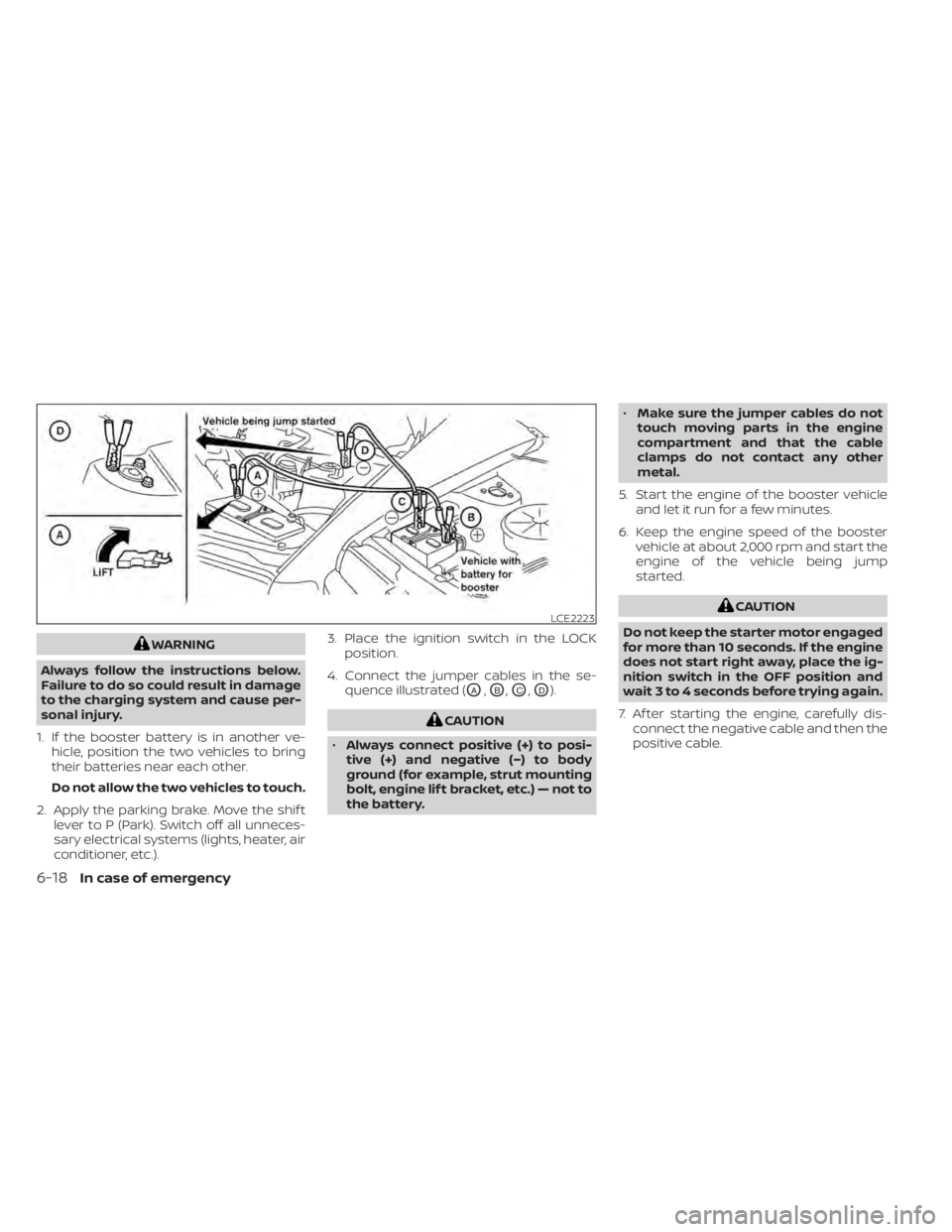
4. Connect the jumper cables in the se- quence illustrated (
OA,OB,OC,OD).
CAUTION
• Always connect positive (+) to posi-
tive (+) and negative (−) to body
ground (for example, strut mounting
bolt, engine lif t bracket, etc.) — not to
the battery. •
Make sure the jumper cables do not
touch moving parts in the engine
compartment and that the cable
clamps do not contact any other
metal.
5. Start the engine of the booster vehicle and let it run for a few minutes.
6. Keep the engine speed of the booster vehicle at about 2,000 rpm and start the
engine of the vehicle being jump
started.
CAUTION
Do not keep the starter motor engaged
for more than 10 seconds. If the engine
does not start right away, place the ig-
nition switch in the OFF position and
wait 3 to 4 seconds before trying again.
7. Af ter starting the engine, carefully dis- connect the negative cable and then the
positive cable.LCE2223
6-18In case of emergency
Page 517 of 644

8 Do-it-yourself
Maintenance precautions.......................8-2
Engine compartment check locations ...........8-3
Engine cooling system ..........................8-5
Checking engine coolant level ................8-6
Changing engine coolant ....................8-6
Engine oil .......................................8-7
Checking engine oil level .....................8-7
Changing engine oil and oil filter ..............8-8
Continuously Variable Transmission (CVT)
fluid ............................................ 8-12
Brake fluid ...................................... 8-12
Windshield-washer fluid ........................8-13
Windshield-washer fluid reservoir ...........8-13
Battery......................................... 8-14
Jump starting ............................... 8-15
Variable voltage control system ................8-16
Drive belt ....................................... 8-16
Spark plugs .................................... 8-17
Replacing spark plugs ....................... 8-17
Air cleaner ..................................... 8-18In-cabin microfilter
.......................... 8-18
Windshield wiper blades ........................8-19
Cleaning .................................... 8-19
Replacing ................................... 8-19
Brakes ......................................... 8-20
Fuses .......................................... 8-21
Engine compartment ....................... 8-21
Passenger compartment ...................8-22
Battery replacement ........................... 8-23
NISSAN Intelligent Key® ......................8-24
Lights .......................................... 8-25
Headlights .................................. 8-25
Fog lights (if so equipped) ...................8-26
Exterior and interior lights ...................8-26
Wheels and tires ............................... 8-29
Tire pressure ................................ 8-29
Tire labeling ................................. 8-33
Types of tires ................................
8-36
Tir
e chains .................................. 8-37
Changing wheels and tires ..................8-39
Page 528 of 644
CAUTION
• NISSAN recommends using Genuine
NISSAN CVT Fluid NS-3 (or equiva-
lent) ONLY in NISSAN CVTs. Do not mix
with other fluids.
• Do not use Automatic Transmission
Fluid (ATF) or manual transmission
fluid in a NISSAN CVT, as it may dam-
age the CVT. Damage caused by the
use of fluids other than as recom-
mended is not covered under
NISSAN's New Vehicle Limited War-
ranty outlined in your Warranty Infor-
mation Booklet.
• Using fluids that are not equivalent
to Genuine NISSAN CVT Fluid NS-3
may also damage the CVT. Damage
caused by the use of fluids other than
as recommended is not covered un-
der NISSAN's New Vehicle Limited
Warranty outlined in your Warranty
Information Booklet.
When checking or replacement of CVT fluid
is required, it is recommended that you visit
a NISSAN dealer for this service. For additional information on brake fluid
specification, see “Recommended fluids/
lubricants and capacities” (P. 10-2).
WARNING
• Use only new fluid from a sealed con-
tainer. Old, inferior or contaminated
fluid may damage the brake system.
The use of improper fluids can dam-
age the brake system and affect the
vehicle's stopping ability.
• Clean the filler cap before removing. •
Brake fluid is poisonous and should
be stored carefully in marked con-
tainers out of reach of children.
CAUTION
Do not spill the fluid on any painted sur-
faces. This will damage the paint. If fluid
is spilled, immediately wash the sur-
face with water.
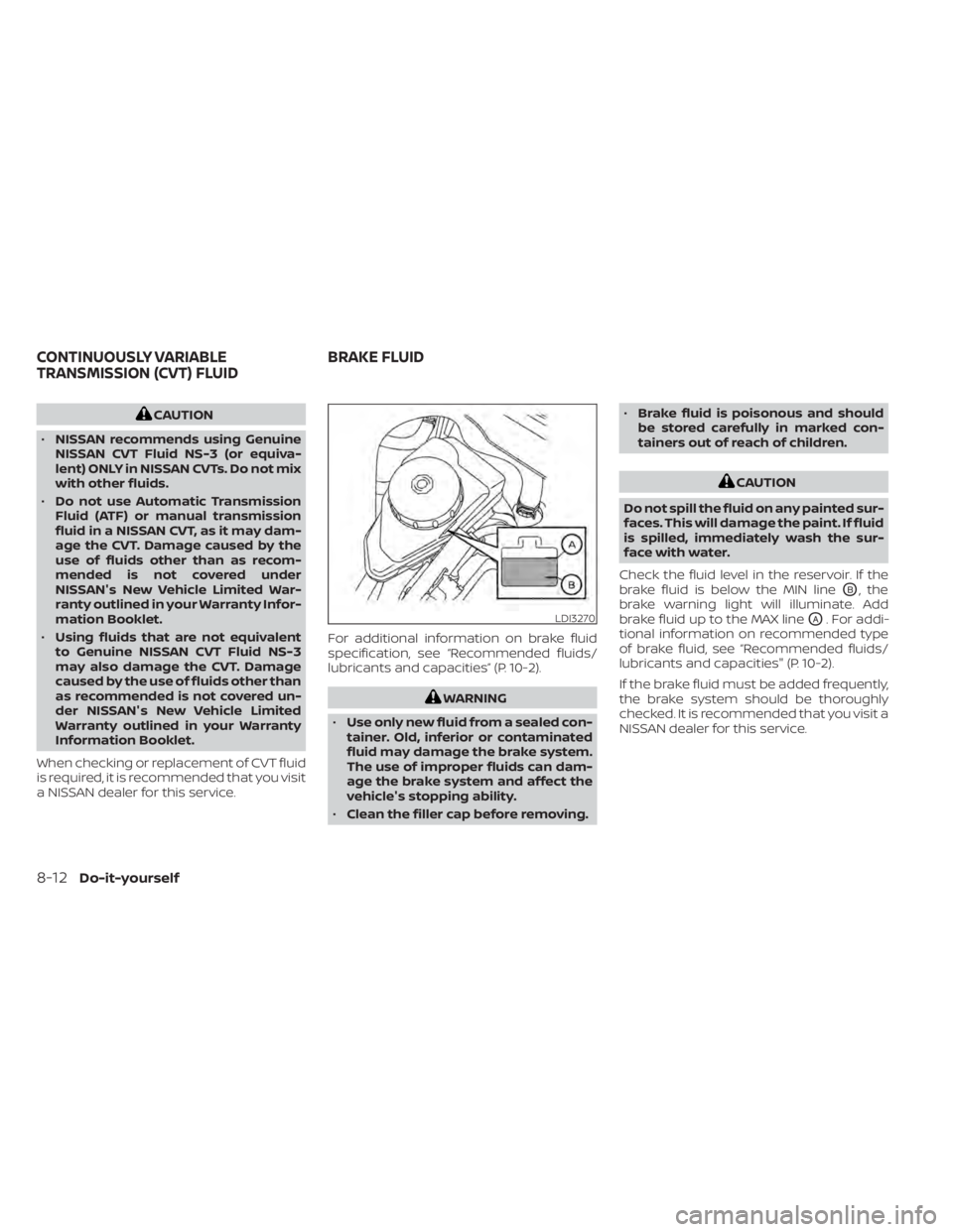
Check the fluid level in the reservoir. If the
brake fluid is below the MIN line
OB, the
brake warning light will illuminate. Add
brake fluid up to the MAX line
OA. For addi-
tional information on recommended type
of brake fluid, see “Recommended fluids/
lubricants and capacities" (P. 10-2).
If the brake fluid must be added frequently,
the brake system should be thoroughly
checked. It is recommended that you visit a
NISSAN dealer for this service.LDI3270
CONTINUOUSLY VARIABLE
TRANSMISSION (CVT) FLUID BRAKE FLUID
8-12Do-it-yourself