2023 HYUNDAI SONATA cooling
[x] Cancel search: coolingPage 490 of 555
Maintenance
8-20
Engine Oil and Filter
The engine oil and filter should be
changed at the intervals specified in the
maintenance schedule.
Drive Belts
Inspect all drive belts for evidence
of cuts, cracks, excessive wear or oil
saturation and replace if necessary. Drive
belts should be checked periodically
for proper tension and adjusted as
necessary.
Fuel Filter
A clogged-up fuel filter may limit the
vehicle driving speed, damage the
emission system, and cause the hard
starting. When a considerable amount
of foreign substances are accumulated
in the fuel tank, the fuel filter should be
replaced.
Upon installing a new fuel filter, operate
the engine for several minutes, and
check the connections for any leakages.
Fuel filters should be installed by an
authorized HYUNDAI dealer.
Fuel Lines, Fuel Hoses and Connections
Check the fuel lines, fuel hoses and
connections for leakage and damage.
Have an authorized HYUNDAI dealer
replace any damaged or leaking parts
immediately.
Vapor Hose and Fuel Filler Cap
The vapor hose and fuel filler cap should
be inspected at those intervals specified
in the maintenance schedule. Make sure
a new vapor hose or fuel filler cap is
correctly replaced.
Air Cleaner Filter
A genuine HYUNDAI air cleaner filter
is recommended when the filter is
replaced.
Spark Plugs
Make sure to install new spark plugs of
the correct heat range.
Cooling System
Check cooling system components, such
as radiator, coolant reservoir, hoses and
connections for leakage and damage.
Replace any damaged parts.
ExpLanation of SCHEDULED maintEnanCE itEmS
Page 493 of 555
08
8-23
Checking the Engine Oil Level
Engine oil is used for lubricating,
cooling, and operating various hydraulic
components in the engine. Engine oil
consumption while driving is normal,
and it is necessary to check and refill the
engine oil regularly. Also, check and refill
the oil level within the recommended
maintenance schedule to prevent
deterioration of oil performance.
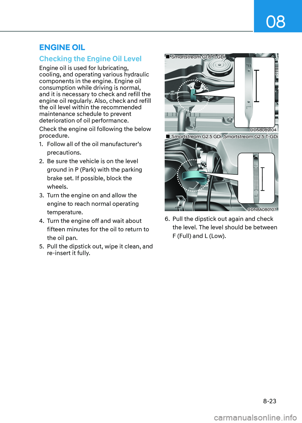
Check the engine oil following the below
procedure.
1. Follow all of the oil manufacturer’sprecautions.
2. Be sure the vehicle is on the level
ground in P (Park) with the parking
brake set. If possible, block thewheels.
3. Turn the engine on and allow the engine to reach normal operating
temperature.
4. Turn the engine off and wait about
fifteen minutes for the oil to return tothe oil pan.
5. Pull the dipstick out, wipe it clean, and re-insert it fully.
ODN8089104
„
„Smartstream G1.6 T-GDi
ODN8A080107
„
„Smartstream G2.5 GDi ,Smartstream G2.5 T-GDi
6. Pull the dipstick out again and check the level. The level should be between
F (Full) and L (Low).
EnginE oiL
Page 496 of 555
Maintenance
8-26
The high-pressure cooling system has a
reservoir filled with year-round antifreeze
coolant. The reservoir is filled at the
factory.
Check the antifreeze protection and
coolant level at least once a year, at
the beginning of the winter season and
before traveling to a colder climate.
NOTICE
• When the engine overheats from
low engine coolant, suddenly adding
engine coolant may cause cracks
in the engine. To prevent damage,
add engine coolant slowly in small
quantities.
• Do not drive with no engine coolant.
It may cause water pump failure and
engine seizure, etc.
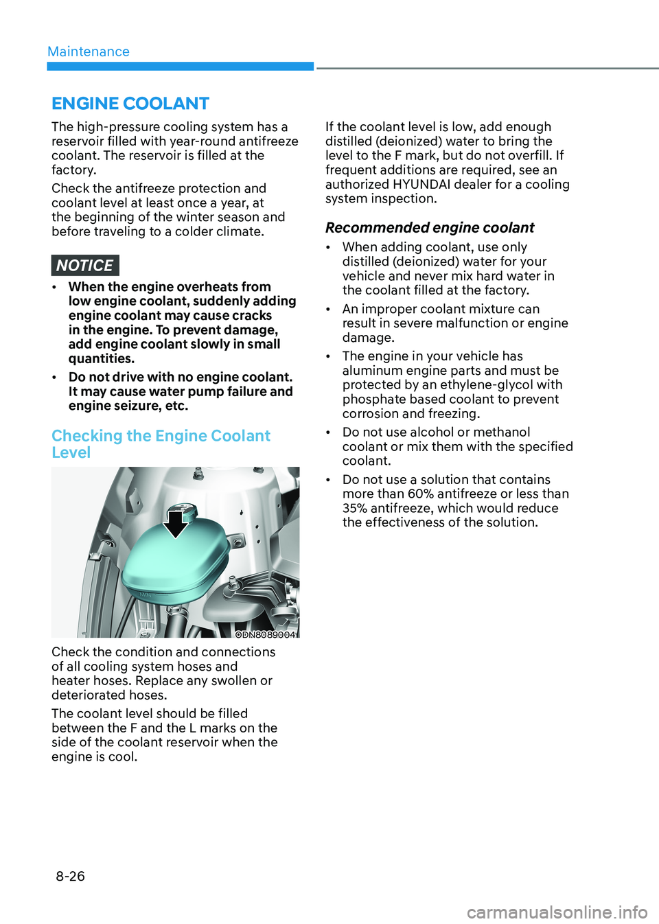
Checking the Engine Coolant
Level
ODN8089004
Check the condition and connections
of all cooling system hoses and
heater hoses. Replace any swollen or
deteriorated hoses.
The coolant level should be filled
between the F and the L marks on the
side of the coolant reservoir when the engine is cool. If the coolant level is low, add enough
distilled (deionized) water to bring the
level to the F mark, but do not overfill. If
frequent additions are required, see an
authorized HYUNDAI dealer for a cooling
system inspection.
Recommended engine coolant • When adding coolant, use only
distilled (deionized) water for your
vehicle and never mix hard water in
the coolant filled at the factory.
• An improper coolant mixture can
result in severe malfunction or engine damage.
• The engine in your vehicle has
aluminum engine parts and must be
protected by an ethylene-glycol with
phosphate based coolant to prevent
corrosion and freezing.
• Do not use alcohol or methanol
coolant or mix them with the specified
coolant.
• Do not use a solution that contains
more than 60% antifreeze or less than
35% antifreeze, which would reduce
the effectiveness of the solution.
EnginE CooLant
Page 497 of 555
08
8-27
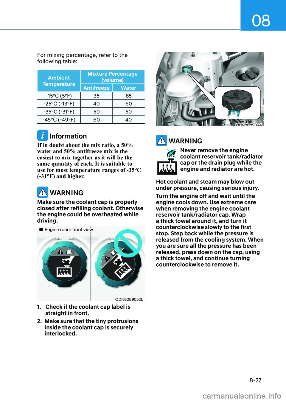
For mixing percentage, refer to the
following table:
Ambient
Temperature Mixture Percentage
(volume)
Antifreeze Water
-15°C (5°F) 35 65
-25°C (-13°F) 40 60
-35°C (-31°F) 50 50
-45°C (-49°F) 60 40
Information
If in doubt about the mix ratio, a 50%
water and 50% antifreeze mix is the
easiest to mix together as it will be the same quantity of each. It is suitable to
use for most temperature ranges of -35°C
(-31°F) and higher.
WARNING
Make sure the coolant cap is properly
closed after refilling coolant. Otherwise
the engine could be overheated while driving.
„„Engine room front view
ODN8089052L
1. Check if the coolant cap label is straight in front.
2. Make sure that the tiny protrusions inside the coolant cap is securely
interlocked.
ODN8089044
WARNING
Never remove the engine
coolant reservoir tank/radiator
cap or the drain plug while the
engine and radiator are hot.
Hot coolant and steam may blow out
under pressure, causing serious injury.
Turn the engine off and wait until the
engine cools down. Use extreme care
when removing the engine coolant
reservoir tank/radiator cap. Wrap
a thick towel around it, and turn it
counterclockwise slowly to the first
stop. Step back while the pressure is
released from the cooling system. When
you are sure all the pressure has been
released, press down on the cap, using
a thick towel, and continue turning
counterclockwise to remove it.
Page 498 of 555
Maintenance
8-28
WARNING
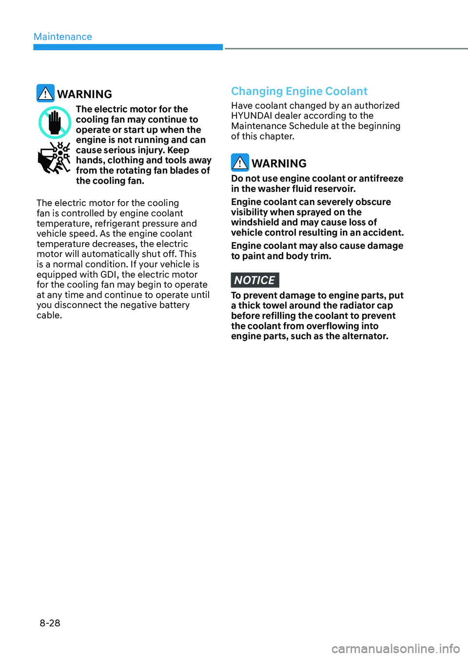
The electric motor for the
cooling fan may continue to
operate or start up when the
engine is not running and can
cause serious injury. Keep
hands, clothing and tools away
from the rotating fan blades of
the cooling fan.
The electric motor for the cooling
fan is controlled by engine coolant
temperature, refrigerant pressure and
vehicle speed. As the engine coolant
temperature decreases, the electric
motor will automatically shut off. This
is a normal condition. If your vehicle is
equipped with GDI, the electric motor
for the cooling fan may begin to operate
at any time and continue to operate until
you disconnect the negative battery cable.
Changing Engine Coolant
Have coolant changed by an authorized
HYUNDAI dealer according to the
Maintenance Schedule at the beginning
of this chapter.
WARNING
Do not use engine coolant or antifreeze
in the washer fluid reservoir.
Engine coolant can severely obscure
visibility when sprayed on the
windshield and may cause loss of
vehicle control resulting in an accident.
Engine coolant may also cause damage
to paint and body trim.
NOTICE
To prevent damage to engine parts, put
a thick towel around the radiator cap
before refilling the coolant to prevent
the coolant from overflowing into
engine parts, such as the alternator.
Page 525 of 555
08
8-55
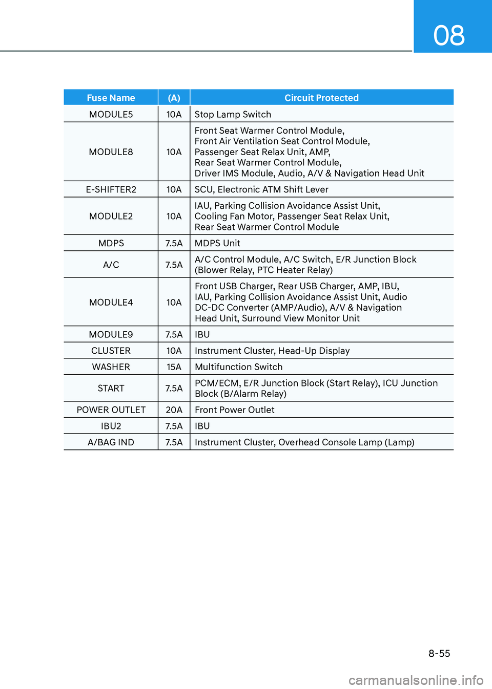
Fuse Name (A) Circuit Protected
MODULE5 10A Stop Lamp Switch
MODULE8 10A Front Seat Warmer Control Module,
Front Air Ventilation Seat Control Module,
Passenger Seat Relax Unit, AMP,
Rear Seat Warmer Control Module,
Driver IMS Module, Audio, A/V & Navigation Head Unit
E-SHIFTER2 10A SCU, Electronic ATM Shift Lever
MODULE2 10A IAU, Parking Collision Avoidance Assist Unit,
Cooling Fan Motor, Passenger Seat Relax Unit,
Rear Seat Warmer Control Module
MDPS 7.5A MDPS Unit
A/C 7.5A A/C Control Module, A/C Switch, E/R Junction Block
(Blower Relay, PTC Heater Relay)
MODULE4 10A Front USB Charger, Rear USB Charger, AMP, IBU,
IAU, Parking Collision Avoidance Assist Unit, Audio
DC-DC Converter (AMP/Audio), A/V & Navigation
Head Unit, Surround View Monitor Unit
MODULE9 7.5A IBU CLUSTER 10A Instrument Cluster, Head-Up Display WASHER 15A Multifunction Switch
START 7.5A PCM/ECM, E/R Junction Block (Start Relay), ICU Junction
Block (B/Alarm Relay)
POWER OUTLET 20A Front Power Outlet IBU2 7.5A IBU
A/BAG IND 7.5A Instrument Cluster, Overhead Console Lamp (Lamp)
Page 527 of 555
08
8-57
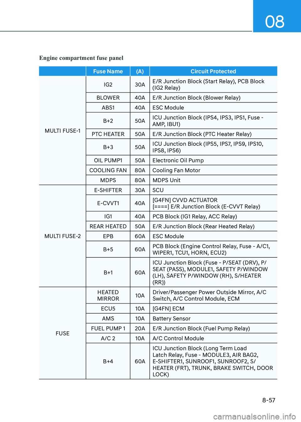
Engine compartment fuse panel
Fuse Name (A) Circuit Protected
MULTI FUSE-1 IG2 30A
E/R Junction Block (Start Relay), PCB Block
(IG2 Relay)
BLOWER 40A E/R Junction Block (Blower Relay) ABS1 40A ESC Module
B+2 50A ICU Junction Block (IPS4, IPS3, IPS1, Fuse -
AMP, IBU1)
PTC HEATER 50A E/R Junction Block (PTC Heater Relay)
B+3 50A ICU Junction Block (IPS5, IPS7, IPS9, IPS10, IPS8, IPS6)
OIL PUMP1 50A Electronic Oil Pump
COOLING FAN 80A Cooling Fan Motor MDPS 80A MDPS Unit
MULTI FUSE-2 E-SHIFTER 30A SCU
E-CVVT1 40A [G4FN] CVVD ACTUATOR
[====] E/R Junction Block (E-CVVT Relay)
IG1 40A PCB Block (IG1 Relay, ACC Relay)
REAR HEATED 50A E/R Junction Block (Rear Heated Relay)
EPB 60A ESC Module
B+5 60A PCB Block (Engine Control Relay, Fuse - A/C1,
WIPER1, TCU1, HORN, ECU2)
B+1 60A ICU Junction Block (Fuse - P/SEAT (DRV), P/
SEAT (PASS), MODULE1, SAFETY P/WINDOW
(LH), SAFETY P/WINDOW (RH), S/HEATER
(RR))
FUSE HEATED
MIRROR 10A Driver/Passenger Power Outside Mirror, A/C
Switch, A/C Control Module, ECM
ECU5 10A [G4FN] ECM AMS 10A Battery Sensor
FUEL PUMP 1 20A E/R Junction Block (Fuel Pump Relay) A/C 2 10A A/C Control Module
B+4 60A ICU Junction Block (Long Term Load
Latch Relay, Fuse - MODULE3, AIR BAG2,
E-SHIFTER1, SUNROOF1, SUNROOF2, S/
HEATER (FRT), TRUNK, BRAKE SWITCH, DOOR
LOCK)